On application of three-dimensional linearized potential-flow model for shallow-water planing
2018-09-25KonstantinMatveev
Konstantin I. Matveev
School of Mechanical and Materials Engineering, Washington State University, Pullman, WA 99164-2920, USA
Abstract Hydrodynamics of planing hulls is affected by proximity to the seabed floor in shallow waters. In this study, a three-dimensional steady linearized model based on the potential theory is applied to model flat planing surfaces at finite water depth and finite Froude numbers.Modeling results for shallow waters agree with experimental data in the subcritical and supercritical regimes sufficiently far from the critical speed that corresponds to the depth Froude number of unity. At the critical speed, nonlinear and unsteady effects become important, and a different modeling approach is required.
Keywords: Shallow-water effects; Planing hulls; Potential flow modeling.
1.Introduction
At sufficiently high speeds, fast boats often rely on hydrodynamic lift to support a significant fraction or even most of their weights. This operational regime when a boat skims on the water surface is called planing. Hulls of planing craft usually employ hard chines for effective water separation on the sides and sometimes transverse steps to reduce the bottom wetted area. Hydrodynamics of planing boats has been extensively studied both experimentally and numerically (e.g.,[10,12] ).
In shallow-water operations of planing craft, a finite water depth affects the boat hydrodynamics. Near the critical speed,corresponding to the depth Froude number of one, a solitary wave is formed at the hull, accompanied by fluctuations in the lift force [9] . The depth Froude number is defined aswhereUis the boat speed,gis the gravity constant, andHis the water depth. In the supercritical regime(FrH> 1), the wave pattern shifts aftward [9] , and the lift force exceeds that in deep water at the same speed.
Some experimental studies with prismatic planing hulls in shallow waters were carried out in the past [2,11] . Toro[13] tested a more complicated hull form. Morabito [9] has recently conducted towing experiments with flat-bottom planing hulls aiming at finer speed resolution over a broad speed range, from the subcritical (FrH< 1) through supercritical speeds.
Theoretical analyses of two-dimensional planing at finite water depth were done by Haskind [3] and Fridman and Tuck[4] . Mousaviraad et al. [10] employed more sophisticated (and computationally demanding) CFD tools to study a variety of planing hull phenomena including shallow water effects.
The purpose of this note is to apply a computationally inexpensive potential-flow model for shallow-water planing.This model is based on a steady three-dimensional linearized approach previously validated for hydrodynamics of planing hulls in deep water [6] , flows with developed air cavities[8] and air-supported marine craft [7] . Due to steady and linearized treatments, the present model is unlikely to perform well near the critical speed, so the main objective here is to determine whether the model is adequate for the subcritical and supercritical regimes of planing hulls in shallow water.

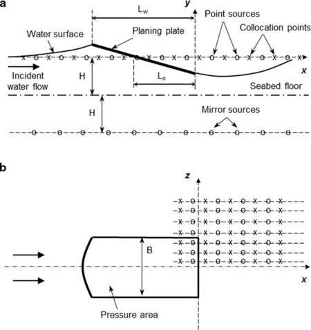
Fig. 1. Geometrical schematic for the numerical model. (a) Side view of a longitudinal section. (b) Top view of a planing surface. Sources and collocation points are shown by circles and crosses, respectively. Only a small part of the numerical domain is depicted. Distances between sources are exaggerated.
2.Mathematical model
The problem schematic for the mathematical model is shown in Fig. 1 . A flat plate with beamBand trim angle τis steadily planing with velocityUon the surface of water with depthH. The water flow is considered to be inviscid and irrotational and symmetric with respect to the plate centerline.The seabed floor is assumed to be rigid. The numerical domain has upstream, downstream and side boundaries, which dimensions are determined from mesh-convergence studies.In this note, a description of the model is focused on dealing with a finite water depth, whereas more detailed mathematical background can be found in previous publications (e.g.,[6–8] ).

The hull trim angle and the water surface slopes are assumed to be small, so the velocity perturbations in the water flow are much smaller than the incident flow velocityU.Hence, a linearized form of the Bernoulli equation can be used as a dynamic boundary condition on the water free surface,whereCp= (p−p0) / ( ρU2/ 2 ) is the pressure coefficient(non-zero only under the plate),pandp0are the pressure values on the water surface and above the free surface, respectively, ρis the water density,uis thex-component of the velocity disturbance,ywis the water surface elevation,λ=2πU2/gis thelengthof propagatingwaveson theunbounded free water surface, andgis the gravitational constant.
In the linearized formulation, the flow perturbations can be modeled with a distribution of point hydrodynamic sources over a horizontal plane aty= 0, coinciding with the undisturbed water surface, and a set of mirror sources on a plane shifted down by 2H, as shown in Fig. 1 . This arrangement eliminates vertical velocities at the seabed floor aty= −H.A velocity potential of each source satisfies the governing Laplace equation in the water domain. The collocation points,where Eq. (1) is fulfilled, are located on a planey= 0and are shifted upstream from the sources. Such a staggered arrangement suppresses the wave reflection from the downstream border of the numerical domain [1] . Due to the problem symmetry with respect to x-y plane, only the starboard portion of the setup (z> 0) can be considered with the mirror sources placed on the port side (z< 0).
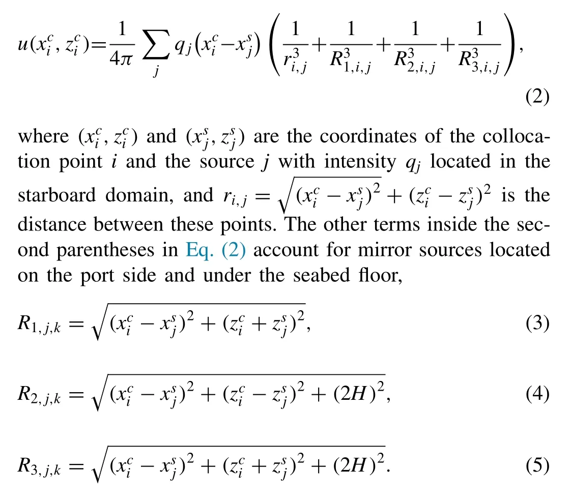
Thex-component of the velocity perturbation in the starboard domain is computed by summing contributions from all the sources,

Besides the dynamic boundary condition ( Eq. (1 )), one needs to impose a kinematic boundary condition on the water surface. In the linearized form, this condition relates the water surface slope to the vertical velocity perturbationvon the planey= 0,

where the vertical velocitiesv1andv2are caused by the sources located on the upper (y= 0) and lower (y= −2H)planes. From the potential flow theory (e.g., [5] ), it is known that a sheet of continuously distributed sources produces an outward normal velocity with a magnitude equal to the half of the local source density, sov1≈ −q/ (2ΔxΔz) . The contribution from the lower layer can be found by adding vertical velocities induced by all mirror sources on the planey= −2H. In the discretized form, Eq. (6) can be re-written as follows,

whereqi−1andqiare the source intensities of the upstream and downstream neighbors of the collocation pointi,Δxand Δzare the intervals between the source locations inxandzdirections, andR2,j,kandR3,j,kare given by Eqs. (4 ) and( 5 ). On the hull surface, the source strengths are directly calculated from the known trim angle of the planing plate. Thus,a linear system of equations ( Eqs. (1 ), ( 2 ), and ( 7 )) is formed for the water surface elevations outside the plate, pressure coefficients on the plate, source intensities, and velocity perturbations. Upon solving this system of equations, a lift force on the hull is found by integrating pressure distribution on the planing plate.
One of the peculiarities in the planing hydrodynamics is the initially unknown pressure area of the planing surface,since the water tends to rise upstream of the plate ( Fig. 1 ).The water spray that may appear in front of the water impingement point on the plate is ignored here similar to Riabouchinsky model commonly for flows with developed cavitation (e.g., [6] ). The wetted length of the plate,Lw, is found iteratively. Initially, the nominal wetted lengthLncan be used forLw( Fig. 1 (a)). Upon the first iteration, one will find that the water surface crosses the hull at a more upstream location,so a new guess for the wetted length can be made, corresponding to the result computed in the first iteration. Upon several iterations of this sort, the wetted length will stop changing.
The mesh-independence studies done in this study suggest that the following numerical parameters are needed to obtain converged results: a distance between sources needs to be at leastB/6 (whereBis the plate beam), the upstream and side boundaries of the numerical domain should be located at 2Bfrom the leading and side edges of the plate, respectively, and the downstream boundary must be placed at 6Bbehind the plate trailing edge.
3.Results
The numerical method described above has been applied for modeling flat-bottom planing hulls at conditions of the tests by Morabito [9] . Two shallow water depths are selected,H/B= 0.75 and 0.5, and one deep-water condition,H/B= 8.01. The nominal hull aspect ratio isLn/B= 3 and the trim angle of the hull is τ= 60. The tested hull speeds cover a range of the beam-based Froude numberfrom verylow(pre-planing)values tothose approaching 3. The highest speeds correspond to the depthbased Froude numbersnear 1 in deep water and close to 4 in shallow waters.
The experimental data of Morabito [9] and numerical results calculated with the present model are shown in Fig. 2 .The beam-based lift coefficientCL=L/ (0. 5 ρU2B2) is plotted as the function of both beam-based and depth-based Froude numbers. In the case of deep water ( Fig. 2 (a) and (b)), there is no effect of the finite depth. The lift coefficient monotonically decreases with increasing velocity, which is caused by reduction of the relative contribution of hydrostatic force to the total lift. This case can serve as another validation example of the current model in deep water.
The effects of finite water depth are pronounced in shallow water cases ( Fig. 2 (c)–(f)). Around the depth Froude number of one (critical regime), a soliton wave at the planing hull was noticed in the experiments [9] , and the measured lift force was unsteady. These observations correspond to scatter in the test data points nearFrH= 1 in Fig. 2 (d) and (f). However, at higher speeds in the subcritical regime the lift force became stable again.
The numerical results indicate a good agreement with test data outside the critical region (FrH~1) in both subcritical and supercritical regimes in the shallow-water cases( Fig. 2 (c)–(f)). Specifically, higher lift forces are observed in the supercritical states at the sameFrBbut smaller water depths. The unsteady, nonlinear flow behavior near critical speeds (FrH~1) cannot be captured by the steady, linearized model applied in this study.

Fig. 2. Lift coefficient dependence on the beam-based Froude number (a,c, and e) and on the depth-based Froude number (b,d, and f). Circles, experimental data; lines, present numerical results. Relative water depths H / B : (a and b), 8.01; (c and d), 0.75; (e and f), 0.5.
4.Conclusions
The potential-flow model previously developed for planing hulls has been modified to account for the finite water depths.In the subcritical and supercritical regimes, where the flow remains steady and flow perturbations are relatively small, the mathematical model predicts experimental findings reasonably well. However, near the critical speed (depth Froude number of one), unsteadiness and nonlinearity in the flow behavior become important in real conditions, and the linearized steady modeling approach should not be used in this situation.
杂志排行
Journal of Ocean Engineering and Science的其它文章
- An integral panel method for the hydrodynamic analysis of hybrid contra-rotating shaft pod propulsors
- RANSE-based simulation and analysis of scale effects on open-water performance of the PPTC-II benchmark propeller
- Efficient three-dimensional high-resolution simulations of flow fields around cylinders
- Development and validation of a coastal ocean forecasting system for Puerto Rico and the U.S. virgin islands
- Numerical study of self-adjoint singularly perturbed two-point boundary value problems using collocation method with error estimation
- Oblique closed form solutions of some important fractional evolution equations via the modified Kudryashov method arising in physical problems
