An integral panel method for the hydrodynamic analysis of hybrid contra-rotating shaft pod propulsors
2018-09-25RuiWangYingXiong
Rui Wang , Ying Xiong
Department of Naval Engineering, Naval University of Engineering, Wuhan 430033, China
Abstract The present work is devoted to developing an efficient method for the analysis and design of hybrid contra-rotating shaft pod (HCRSP)propulsors. The geometry of contra-rotating propulsor (CRP) was then analyzed, and a steady integral panel method that treats the forward and aft propellers as a whole part is presented. During the study, the control equation of the steady integral panel method for CRP is derived in detail. From the experience of developing an integral panel method for CRP, the characteristics of panel singularity strength in HCRSP propulsor was analyzed. Based on this analysis, an integral panel method for HCRSP propulsor is developed and the wake model discussed.Then, the method is applied in the performance analysis of HCRSP propulsor. Comparison between experimental data and numerical results shows that the steady integral panel method has good accuracy in terms of open water performance. Regarding the latter, the error source in the steady integral panel method is discussed.
Keywords: Hybrid contra-rotating shaft pod propulsor; Surface panel method; Integral calculation model; Wake model.
1.Introduction
Hybrid contra-rotating shaft pod (HCRSP) propulsor is defined as propulsion system which consists of a conventional shaft propeller in before and a pod propulsion or Z-drive in behind. The application of this type of propulsive device to modern ships becomes even more attractive, considering the recent developments in podded propulsion and the increased emphasis on fuel economy. Despite the hydrodynamic advantages that the HCRSP propulsors concept could offer,application to ships has been limited. A reasonable explanation can be given by considering the structure complexity,the lacking of effectively design approach. Since the HCRSP propulsor was first applied to full-scale ships by ABB in 2001, test procedures [1–3] and viscous flow methods[4,5] have been developed. According to these studies and the works of Chang and Seokcheon [6] , Quereda et al. [7] ,and Sasaki et al. [8] , guidelines for HCRSP propulsor model tests were first recommended by the 27th ITTC Propulsion Committee [9] . Detailed research on the computer processing of the viscous numerical method for HCRSP propulsor analysis has been conducted by Wang et al. [10] . Additional interesting research on HCRSP propulsor has been carried out under the auspices of the EU TRIPOD project [11] , in which a conventional propeller was replaced by a contracted and loaded tip (CLT) propeller to improve propulsion efficiency.
Experimental methods and the viscous flow method have used in the analysis of HCRSP propulsors; however, little research has focused on the potential flow method, due mainly to the complexity of such an iterative method [12–14] when applied to the analysis of HCRSP propulsors. While an iterative method is widely used in the study of propulsors consisting of two components, an iterative process could become very complicated when applied to more than two components,such as a HCRSP propulsor. In light of the limitation of a numerical method based on potential flow, it is very difficult to design a HCRSP propulsor.

Fig. 1. The position of forward propeller and aft propeller.
The purpose of this paper is to provide a solution to the analysis of HCRSP propulsors using the surface panel method. To that end, a steady surface panel method that treats a HCRSP propulsor as a complete part is presented. Thus, this work strives to devise a high efficiency numerical method for the performance design and analysis of HCRSP propulsors; it also provides research ideas for propulsors consisting of more than two components.
2.Numerical method
When the surface panel method is applied, the flow around the propeller is considered to be incompressible, inviscid, and irrotational; moreover, the viscous wake flow is considered to be no thickness boundary of potential flow. The flow condition around propeller and its wake can be simulated by inducing singularity on the propeller and wake surface. Then, the perturbation potential φ, whose spatial derivatives represent the component of the perturbation velocity vector, satisfies the Laplace equation. From Green’s formula, an integral equation [15–17] can be written for unknown potential values at pointpas follow:

where the field pointpand control pointqis on the surface of propeller and its wake.SBis the surface of propeller and hub,SWis the surface of the wake,r(p,q) is the distance between pointspandq, andnqis the unit normal vector pointing into the flow. The value of ∂ φ (q)/ ∂nqon the propeller can be determined by boundary conditions while on the wake its value is zero; the value of φ(q) on the wake can be determined by the Kutta condition [18] . In the numerical process, the propeller and vortex sheet are discretized with hyperboloidal panels carrying constant strength sources and dipoles. For a steady problem of a single traditional propeller,only one blade (the key blade) needs to be solved due to the symmetrical in- flow condition and propeller geometry. This will significantly reduce the surface panel and solution time.GeneralizingSBandSWin Eq. (2.1) , the governing equation for a HCRSP propulsor is obtained. However, the symmetry of the singularity strength in forward or aft propeller is broken even in uniform flow. In this case, the HCRSP propulsor could not be solved as a unit by the old surface panel method which only solves for one bale of a propeller. In addition, the processing is very complicated when an unsteady surface panel method [19,20] is employed to obtain the solution. In order to establish an integral panel method for HCRSP propulsors,a steady integral panel method for contra-rotating propulsors(CRPs) is discussed first.
2.1. Integral panel method for CRPs
For convenience, a four bladed forward propeller and a five bladed aft propeller system was chosen as our experimental CRP. It should be noted here that the conclusions reached are also suitable for other numbers of blades. A diagram of the CRP is shown in Fig. 1 . The forward propeller blades are represented by dashed lines and the blade numbers are denoted by Roman numerals I–IV. The aft propeller blade is represented by solid lines and the blade numbers are denoted by Arabic numerals 1–5. The position of solid line (or dash line) is the position of aft (or forward) propeller reference line.
In Fig. 1 , for position 1, blade I overlaps with blade 1 and then rotates the forward (or aft) propeller by θ, to reach position 2, in which blade IV overlaps with blade 5. Rotating the forward (or aft) propeller in position 1 by five times θ,to reach position 3, where blade IV overlaps with blade 1.As shown in Fig. 1 , for uniform flow conditions, the force of the forward and aft propeller blade change periodically and the period are different. But the periods of the forward and aft propeller forces are the same, and thus the forces of the propellers in positions 1, 2 and 3 as shown in Fig. 1 are the same. In some sense, the propeller force is an average force in terms of open water performance. We can choose several positions as the solving position, and then average the singularity strength at these positions. The detailed processing is discussed in the following section.
We choose blade I of forward propeller and blade 1 of aft propeller as the solving blades (key blades), and then rotate blade I (or blade 1) one revolution with interval angle of θ(as labeled in Fig. 1 ), taking every multiple of θ as the solving position. Obviously, in every solving position, the forces of the forward and aft propellers are the same. For the blade numbers chosen in this paper, we can know that the value of θ is 18 °and we define:

whereZ1is the blade number of forward propeller andZ2is the blade number of aft propeller.S0could be considered as the number of solving position.
According to Eq. (2.1) , paneliof the key blade in every solving position is written as

k1is the blade number of forward propeller,k2is the blade number of aft propeller,Mis forward key blade mesh number,Nis aft key blade mesh number,MWis forward propeller wake mesh number,NWis aft propeller wake mesh number.SubscriptSrepresent solving position andS= 1 corresponds to position 1 in Fig. 1 , where the value of angle between blade I and blade 1 is 0 °,S= 2 corresponds to the position 2 in Fig. 1 , and so on.is the in fluence of control pointjink1blade on field pointiat theSangle position;is the velocity potential of control pointjink1blade at theSangle position. The superscript and subscript in the other constructions mean the same as inandTaking the average of Eq. (2.3) whenStakes different values,

In order to solve Eq. (2.4) with the steady surface panel method, some numerical processing is required. First, the potentials of the forward and aft propellers are represented separately:

where Eq. (2.5) is the potential expression of the panel in the forward propeller key blade. Items labeled 1 in Eq. (2.5) are the in fluence of the forward propeller panel on itself, while those labeled 2 are the in fluence of the aft propeller panel on the key blade panel. Items labeled 1 in Eq. (2.6) are the in fluence of the forward propeller panel on the key blade panel and those labeled 2 are the in fluence of the aft propeller panel on itself. Since items labeled 1 or 2 have the same changing tendency whenStakes different values, one item is chosen as the representation of items labeled 1 and 2.

where ellipsis represents the unlisted items in Eqs. (2.5) and(2.6) . The first item on the right hand side of Eq. (2.7) is the in fluence of the forward propeller control point on the forward propeller field point;takes the same values whenStakes different values andk1takes the same values. The first item on the right hand side of Eq. (2.7) can then be written as

Referring to Fig. 1 , in Eq. (2.9) , theis changes periodically andin different blades has a corresponding relation whenStakes different values. For example, in terms of position 1 and position 2 in Fig. 1 , the value of φ in blade I whenS= 2 is the same as the value of φ in blade Ⅱ whenS= 1 , and so on. Obviously, this equivalent relationship of the forward propeller blade will repeatS1times whenSchanges from 1in Eq. (2.9) can be written as


Eq. (2.11) is final expression for the first item on the right hand of Eq. (2.7) . The second item on the right hand side of Eq. (2.7) is the in fluence of the aft propeller panel on the forward propeller panel. The value ofis different whenStakes different values, even for the same value ofk2.However, there is still a corresponding relationship betweenwhenStakes different values. Taking positions 1 and 3 in Fig. 1 as an example, the values ofin blade 1 are the same, but the values ofare different. Then,the items having the samevalues can be merged. The in fluence coefficientof blade 1 on blade I under position 2 has the same value as blade 2 on blade I under position 3, andin blade 1under position 2 is the same asin blade 2 under position 3. This corresponding relationship can be generated for other blades with differentSvalues. Then,the second item on the right hand side of Eq. (2.7) can be written as

whereis de fined in

whereis the in f uence coefficient of control pointlin aft propeller blade on the field poiin forward propeller blade under positionS= 1 ; the otherhave similar meaning. For the sake of clarity, the subscriptSin Eq. (2.13) is replaced by the specific figure of the blade number chosen in this paper.For all of the superscripts infor Eq. (2.13) ,k2= 1 . This is because of the corresponding relationship between values ofw henStakes different values, as discussed previously. In numerical processing,is approximately equal for different value ofk2; this will be discussed in the forthcoming error analysis ( Section 4 ). Eq. (2.12) can then be written as


Combining Eqs. (2.11) and (2.15) , the final expression of Eq. (2.7) can be written as

Fig. 2. Positions of forward and aft propellers and pod.

The items represented by the ellipsis have similar characteristics as the first and second items on right hand side of Eq. (2.16) . Definingthe final expression of Eq. (2.5) can then be written as

Unifying Eqs. (2.17) and (2.18) , we obtain the final expression of Eq. (2.4) :
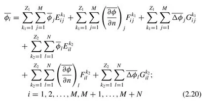
whereEis defined in Eq. (2.21) . Replacing theCin Eq. (2.21) byBandW, we obtain the expression ofFandG.

where subscriptjis the control point in forward propeller blade,lis the control point in aft propeller blade. Eq. (2.20) is the control equation of integral panel method for CRP, which only needs to solve key blade of forward and aft propellers.
2.2. Integral panel method for HCRSP propulsors
An integral panel method for HCRSP propulsor is now presented based on the work detailed in the preceding section.To achieve correspondence with the method used in that Section 2.1 , four blades for the forward propeller and five blades for the aft propeller are chosen for the HCRSP propulsor. A diagram of the HCRSP propulsor is shown in Fig. 2 .
In Fig. 2 , the lines and labels have the same meaning as in Fig. 1 , except for the pod, which is represented by a T shaped line, which is the centerline of the pod. According to the established integral panel method for CRPs; the solving positions for the forward and aft propellers are unchanged. Upon rotating the pod a cycle with an interval angle of θ, we choose every multiple of θas a solving position. Eq. (2.20) represents an average force condition for CRPs, and for this condition,the singularity strength for different blades in either forward or aft propeller is symmetric. When the pod is added, this symmetry will be broken. The CRP, however, can be considered as a whole part in the analysis of the integral equation for the HCRSP propulsor. Thus, the velocity potential φof field pointiin forward and aft propeller key blades under different positions is written as Eq. (2.22) , while Eq. (2.23) is written for the velocity potential φof the pod:
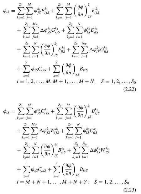
whereYis the pod mesh number.E,FandGhave the same expression as that in Eq. (2.20) . The other subscripts and superscripts have the same meanings as in Eq. (2.3) except for subscriptS. In Eqs. (2.22) and (2.23) ,Sis the position of the pod withS= 1 corresponding to position 1 in Fig. 2 ,S= 5 corresponding to the position 2 in Fig. 2 , and so on. Taking average of Eqs. (2.22) and (2.23) whenStakes different values.
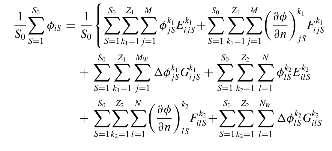

Examining Eqs. (2.24) and (2.25) , we also select three items as shown in Eqs. (2.26) and (2.27) due to the fact that the other items exhibit the same changing trend with the selected items:

where the ellipsis represents the unlisted items in Eqs. (2.24) and (2.25) . The forward and aft propellers were considered as a single unit in the analysis of Eq. (2.26) , therefore, the values ofandremain the same whenStakes different values. The first and second items on the right hand side of Eq. (2.26) can be expressed as


whereEixcomplies with Eq. (2.30) . In the analysis of Eq. (2.29) ,iis the field point of the forward propeller, and the final expression would be the same wheniis the field point of the aft propeller:

The final expression of Eq. (2.26) is obtained as shown in Eqs. (2.28) and (2.29) . For Eq. (2.27) , then the first item on the right-hand side was the influence of the forward propeller on the pod and the second item was the influence of the aft propeller on it. In addition, the fluctuation caused by the aft propeller was ignored in the analysis of the first item and the fluctuation caused by the forward propeller was ignored in the analysis of the second item. This treatment is similar to the case without an aft (or forward) propeller when the influence of the forward (or aft) propeller on the pod is analyzed. Now, the first and second items on the right-hand side of Eq. (2.27) can be written as
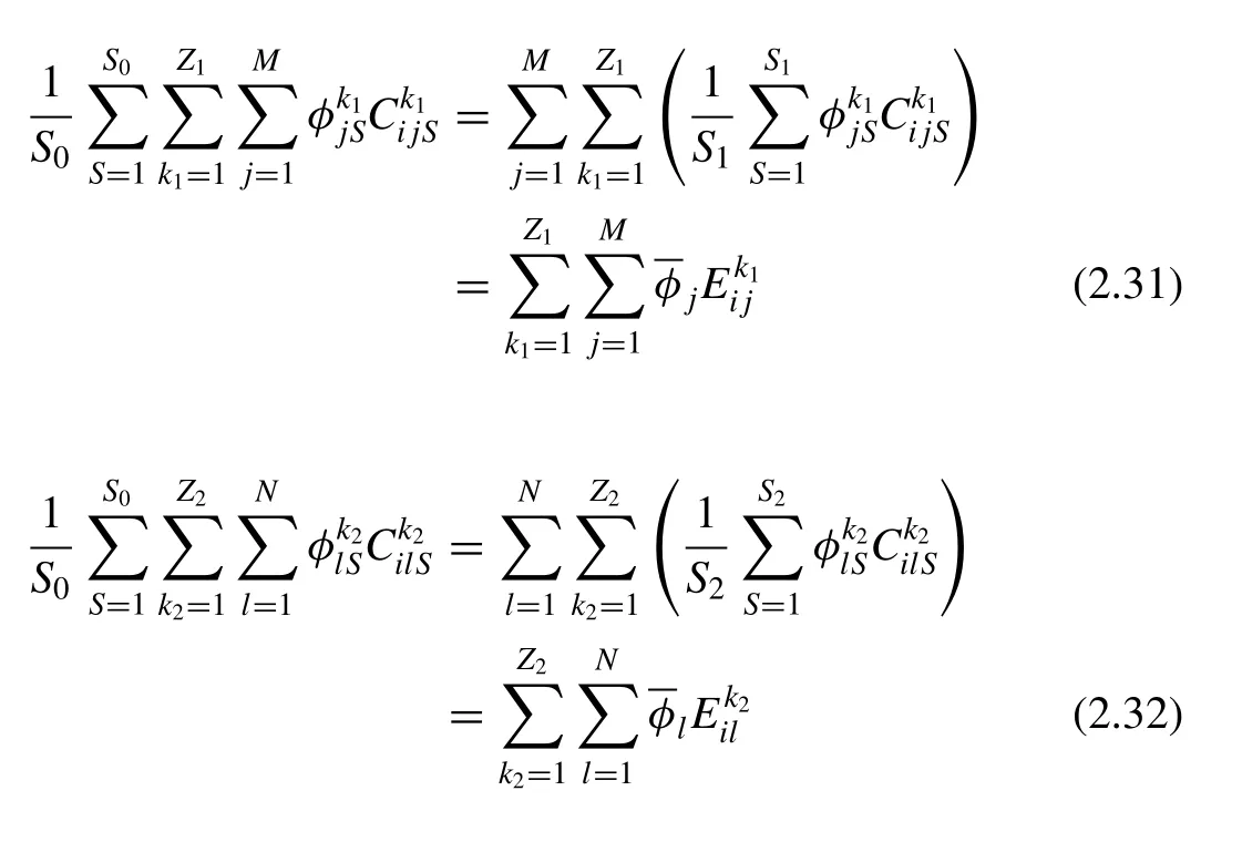
whereandsatisfy Eqs. (2.33) and (2.34) :

The third item on right-hand side of Eq. (27) is the influence of pod on itself, andCixSremains unchanged for different values ofS. Eq. (27) can then be written as

Based on the discussion of Eqs. (2.26) –(2.35) , the velocity potential of the panel in the propeller and pod could be expressed by the same equation, and the integral panel method equation for the HCRSP propulsor is obtained as follow:
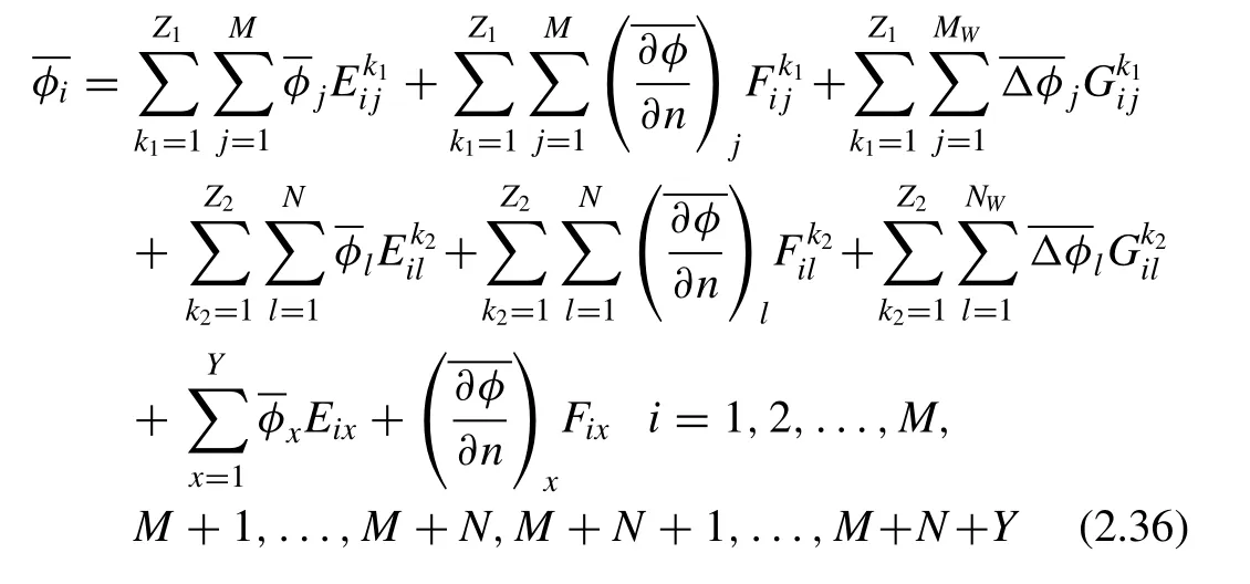
where the influence coefficientE, for instance, is defined in Eq. (2.37) and the otherFandGhave the same expression:
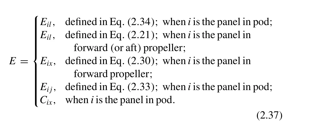
For Eq. (2.36) , only one blade of the forward and aft propellers needs to be solved, and then the steady surface panel method can be applied, greatly simplifying the calculation for HCRSP propulsors.
According to the derivation process for Eq. (2.36) , we realize that Eq. (2.36) can be applied for other blade numbers in HCRSP propulsors and while the influence coefficient should be revised, the expression for the influence coefficient is the same as in Eq. (2.37) .

Table 1 Pod parameters.

Table 2 Parameters of propellers.
3.Numerical results
The wake model exerts an important influence on the numerical results of the surface panel method. The wake pitch of the integral panel method for HCRSP propulsors was modified based on the propeller’s actual wake flow, and the modification is given as follow:

wherexwakeis the axial coordinate of the forward propeller wake;xA−planeis theaxialcoordinateofthe aftpropellerdisk plane; βHFis the wake pitch angle of the forward propeller in the HCRSP propulsor and βSFis the corresponding wake pitch angle without the pod and aft propeller, this relationship is the same to aft propeller wake pith angle βCAand βSA;ωF1,ωF2and ωAare modifying coefficients for the wake pith angle that vary with the operating conditions of the propellers, also empirical calculation may also play an important role in the determination of these coefficients. As shown in Eq. (3.1) , the suction effect [21] of the aft propeller and the blocking effect[22] of the pod were the main considerations in the modification of the wake model for HCRSP propulsors. Some other aspects of the wake model should be noted. First, the wake geometry should not be located inside the pod or aft propeller;second, the wake shed from the root of the propeller should be close to the pod surface; third, the influence-coefficient calculation of a wake panel close to an aft propeller or pod should be carefully.
A HCRSP propulsor [10] was analyzed by Eq. (2.36) and the numerical results were compared with the experimental data [10] . The main parameters of HCRSP propulsor are shown in Tables 1 and 2 ; the diagram of pod is shown in Fig. 3 . The distance between forward and aft propeller is 0.4545DF, whereDFis the diameter of forward propeller.
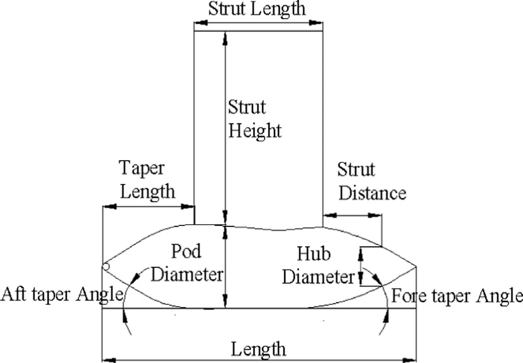
Fig. 3. The diagram of pod.
TheKTF,KTA,KTU,KQFandKQAwere defined in Eq. (3.2) .KTFis the thrust coefficient of forward propeller,KTAis the thrust coefficient of aft propeller,KTUis the thrust coefficient of aft propeller and pod,KQFis the torque coefficient of forward propeller,KQAis the torque coefficient of aft propeller.
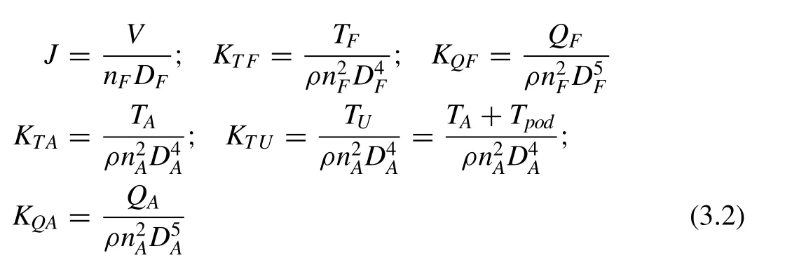
where ρis flow density,TFis forward propeller axial thrust,QFis forward propeller axial torque,TAis aft propeller axial thrust,Tpodis pod axial thrust,QAis aft propeller axial torque,Vis inflow velocity,nFis forward propeller rotating speed,nAis aft propeller rotating speed,DAis the diameter of aft propeller. The total grid numbers of HCRSP propulsor are 2687 and the grid number of the forward propeller, aft propeller and pod are 928, 694 and 1065, respectively. Numerical results are shown in Figs. 4 and 5 and the ‘integral method’ is the result of integral panel method established in Eq. (2.36) .
Analysis shows that the relative error of the numerical results in design pointJ= 0. 781 is within 5%. In addition, the relative error of the forward propeller thrust and torque coefficient is within 2% in the design point, and for the other points, it is within 3%, while the relative error of the aft propeller thrust and torque coefficient is about 5% which is larger than that of the forward propeller. In terms of application in engineering, the integral panel method satisfies the demand for precision. A preliminary analysis of the aft propeller results indicates that the interaction between the forward and aft propeller wake was not considered in the modification of the wake model. This interaction has an important effect on the aft propeller result as it is close to the aft propeller. Further research on the wake model of HCRSP propulsors should be done, but we do not discuss that here since the main goal of this paper is to provide a highly efficient method for analyzing and designing HCRSP propulsors.
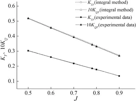
Fig. 4. Open water performance of forward propeller.
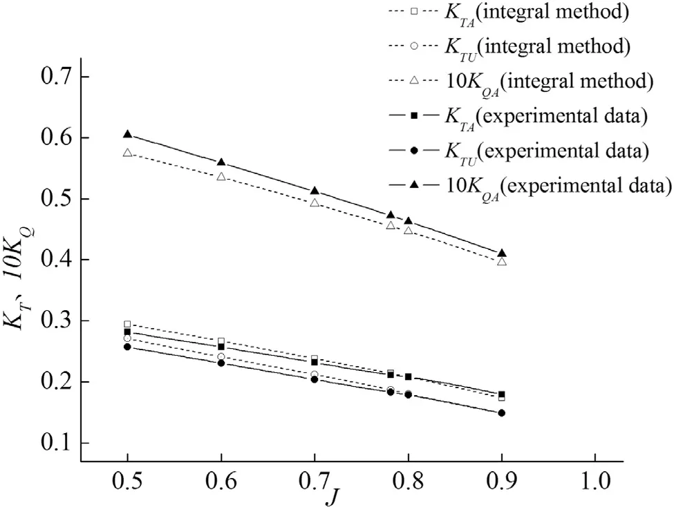
Fig. 5. Open water performance of podded propulsion.
4.Error analysis
The wake model provides a hypothesis for non-potential flow, which is a theoretical defect of the surface panel method.However, many researchers have shown that there is good agreement between numerical results and experimental data with a correct wake model. Except for the error caused by the wake model, four other approximation processes have been introduced in the analysis of the integral panel method in this paper, and the rationale of each of these processes is now discussed.
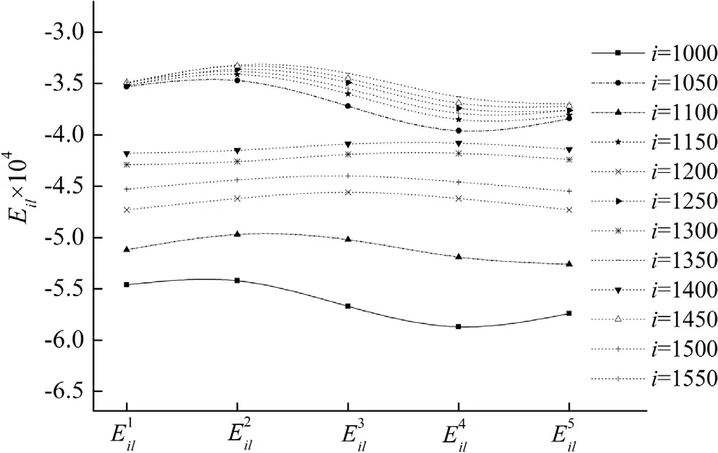
Fig. 6. The comparison of influence coefficient when l is 100.
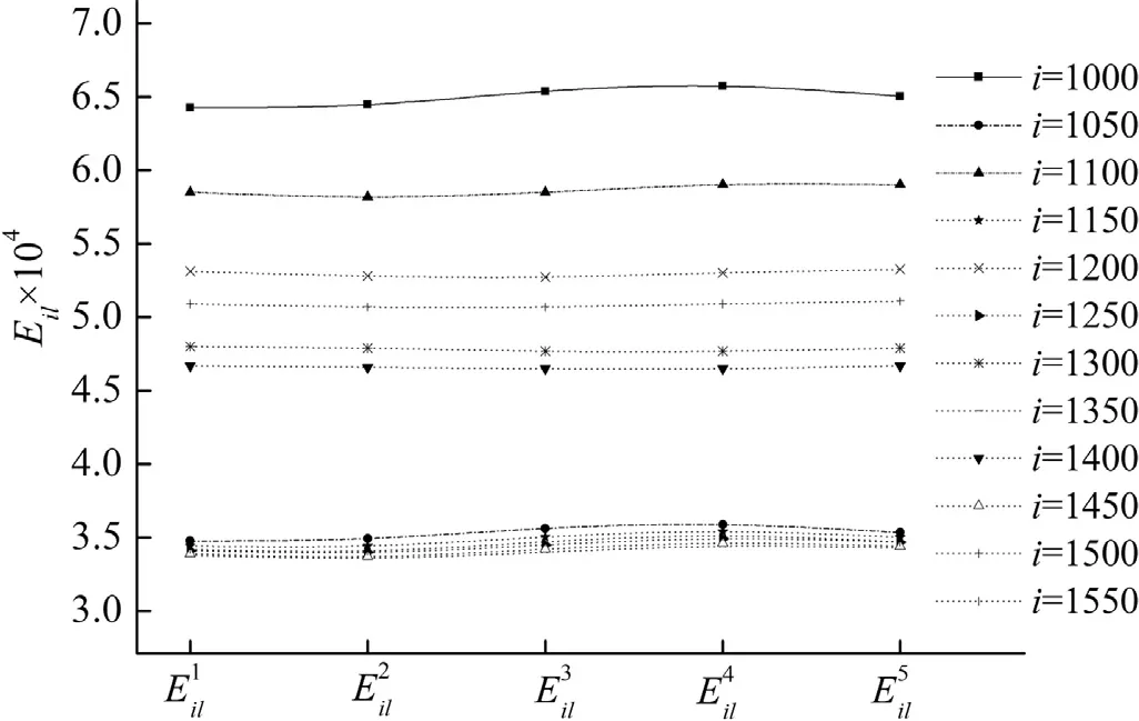
Fig. 7. The comparison of influence coefficient when l is 500.
First, in Eqs. (2.13) and (2.19) , and in the analysis of Eq. (2.29) as well, the influence coefficients were considered to be approximately equivalent. For example, in Eq. (2.13) ,for different values ofk2,Numerical comparisons of the influence-coefficient values are shown in Figs. 6 –9 explain this equivalent relationship. For, the 100th and 500th points were chosen as the control pointland the 50th to 600th points at intervals of 50 points were chosen as the field pointi. Forthe 200th and 400th points were chosen as the control pointjand the 1000th to 1550th points at intervals of 50 points were chosen as the field pointi. According to the grid division,i≤928 represents the field point in the forward propeller key blade,while 928 <i≤ 1622 represents the field point in the aft propeller key blade.
As shown in Figs. 6 –9 , the value of the influence coefficient is on the order of 10−4, and for different values ofk2, the differences between most of thevalues are within 1% except that a small number of points reach 7%; thevalues show similar characteristics. The influence coefficient between the pod and propeller is also been studied in this paper and its values are within the range of the variation shown in Figs. 7 –9 . Thus, we conclude that the error caused by the approximation process of Eqs. (2.12) and (2.29) is acceptable for obtaining the numerical solution.
Second, for Eqs. (2.3) , (2.22) and (2.23) , a finite number of positions were selected as the solving position and the propeller force between the selected angles was ignored. According to the results reported in Refs. [12,23–25] , the fluctuation of the propeller force at angle θ(labeled in Fig. 2 ) is within 1%. Therefore, ignoring this force fluctuation is sensible when calculation HCRSP propulsor performance.

Fig. 8. The comparison of influence coefficient when j is 200.
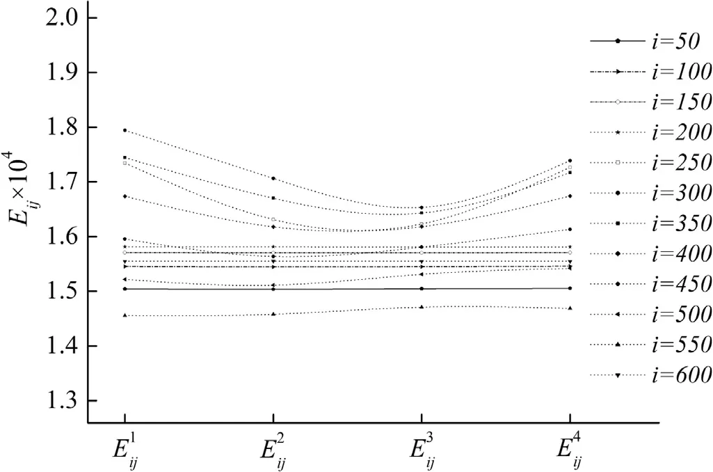
Fig. 9. The comparison of influence coefficient when j is 400.
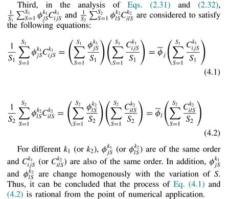
Lastly, the averaging process of propeller force was resolved by determining average velocity potential. This can be expressed as

wherenis number of φiitems; φiare of the same order with differentn. Thus, the numerical process embodied by Eq. (4.3) can be considered rational from the point of numerical application.
Based on the foregoing discussion, it is concluded that the numerical results from the integral panel method established in this paper are reliable.
5.Conclusion
An integral panel method for performance analysis of HCRSP propulsors was presented based on the discussion of the CRP integral panel method. The governing equation for the integral panel method was discussed in detail, and a HCRSP propulsor was analyzed using the method. Numerical results were compared with experimental data and show good agreement with them. The method therefore provides a highly efficient method for the performance analysis and design of HCRSP propulsors, which is the main goal of this research.The integral panel method presented in this paper is also suitable for other propulsion system consisting of more than two components. In addition, the wake model of the integral panel method was discussed briefly, but further research on wake geometry is needed in order to improve the computational accuracy and stability of this method as it relates to the wake model.
Acknowledgments
The present work is supported by the National Natural Science Foundation of China (Grant no. 51479207 ).
杂志排行
Journal of Ocean Engineering and Science的其它文章
- RANSE-based simulation and analysis of scale effects on open-water performance of the PPTC-II benchmark propeller
- Efficient three-dimensional high-resolution simulations of flow fields around cylinders
- On application of three-dimensional linearized potential-flow model for shallow-water planing
- Development and validation of a coastal ocean forecasting system for Puerto Rico and the U.S. virgin islands
- Numerical study of self-adjoint singularly perturbed two-point boundary value problems using collocation method with error estimation
- Oblique closed form solutions of some important fractional evolution equations via the modified Kudryashov method arising in physical problems
