Integrated optimization on aerodynamics-structure coupling and flight stability of a large airplane in preliminary design
2018-06-28XiaozheWANGZhiqiangWANZhuLIUChaoYANG
Xiaozhe WANG,Zhiqiang WAN,Zhu LIU,Chao YANG,*
aSchool of Aeronautic Science and Engineering,Beihang University,Beijing 100083,China
bKey Laboratory of Aircraft Advanced Design Technology,Ministry of Industry and Information,Beijing 100083,China
1.Introduction
Taking into account increasing environmental problems and economic requirements,the airline industry and airplane designers are seeking more efficient and comfortable airplanes.1,2Research on airplane designs is therefore focused more on increasing the lift-to-drag ratio,reducing the structural weight,and improving the stability.The airplane design process is in general divided into three phases,i.e.,the conceptual design phase,the preliminary design phase,and the detailed design phase.In the conceptual phase,main parameters,such as airfoil,planform shape,structural layout and stiffness distribution,are initially determined by empirical formulas and engineering estimation formulas,3and it is guaranteed that the overall performance of the airplane can reach the design targets.In the preliminary phase,the aerodynamic shape,structural layout,and structural sizes are further re fined and optimized,and the aerodynamic shapeis finally determined.Highly accurate methods,suchas Computational Fluid Dynamics(CFD),Finite Element Method(FEM),and so forth,are employed in this phase to ensure that the scheme can meet the design requirements.The detailed design phase contains structural size design,strength checks,various types of tests,and detailed design drawings of components used for manufacturing.4
Though every design phase is very important,the preliminary design phase has a special place since it is the continuation of the conceptual design phase and the base of the detailed design phase.The earlier the appropriate aerodynamic shape,structural layout,and sizes can be determined,the more economical the whole design process will be,avoiding costly redesigns and corrections later,so the preliminary design has enormous potential in enhancing the overall performance.5
Conventional methods perform the aerodynamic,structural,and stability designs in a specific sequence.The aerodynamic shape,which has the maximum lift-to-drag ratio and a reasonable geometric shape,6,7is designed first.Given the aerodynamic shape,the structural layout5,8and structural sizes9,10are designed to minimize the structural weight subjected to multiple constraints.Following that,a jig shape will be obtained referring to the predefined aerodynamic shape and structure.11However,airplane design is a complex process requiring a detailed consideration of the coupling effects between different disciplines.Conventional designs excessively depend on engineering experience,which will lead to repeated iterations and low efficiency,so it can hardly adapt to the designs of modern airplanes,especially the preliminary phase with an enormous potential.Multidisciplinary Analysis and Optimization(MAO)could take disciplines containing aerodynamics,structure, flight dynamics,etc.into consideration simultaneously and has the capability to overcome the limitations of conventional methods,so it has been applied widely in modern airplane designs.12–14
A crucial challenge of MAO is the trade off between analytical accuracy and computational burden.Many engineering software systems contain modules for aeroelastic analyses.Doublet-Lattice theory for static aeroelasticity and flutter analyses adopted in MSC.Nastran is a type of low-order panel methodology,15and the modal approach adopted in ZONAIR formulates a reduced-order trim system combining a unified high-order panel methodology and structural modes.16Although these methods can be employed with much less computer time than that of direct methods,the analytical accuracy of aerodynamics or structures cannot satisfy the requirements of MAO for airplane designs in the preliminary phase.A three-dimensional flight load method for static aeroelasticity analysis is applied.17Aerodynamic analysis and elastic correction are based on Aerodynamic Influence Coefficient(AIC)matrices generated by a high-order panel method,which can guarantee both the accuracy and efficiency.Though CFD simulations based on Reynolds-averaged Navier-Stokes (RANS) equations can simulate intricate flow,its massive computational burden is unacceptable.Steady flight conditions make up most of the flight time of a large airplane,so some viscous/inviscid iteration methods18,19are more suitable for a large airplane under cruise conditions with moderate flow separation.The disturbance in cruise conditions is weak compared with that in the steady state,and therefore,the small-disturbance theory isvalid for cruise stability analysis.To further reduce the computational burden,the Kriging method has found widespread use owing to its promising potential.20,21As a Response Surface Method(RSM),the Kriging model22is developed in the field of spatial statistics and geostatistics,which is the most widely used RSM compared with the polynomial-based model.
A gradient-based algorithm,which is the major method in some commercial structural optimization software systems,23has the advantage of rapidity,but it is apt to converge to a local optimum solution,and sometimes the derivatives are impossible to calculate.On the contrary,evolutionary algorithms are suitable to seek the optimal solution for these MAO problems,and Genetic Algorithm(GA)is the most widely used global algorithm.24
To exploit the immense potential of a large airplane in the preliminary design phase and avoid the design limitations of conventional methods,an integrated optimization method accounting for aerodynamics,structure,and stability is proposed,and the optimal wing geometry shape,front/rear spar positions,and structural sizes are obtained simultaneously.The three-dimensional flight load method is used for static aeroelasticity analysis,and the p-k method provided by MSC.Nastran is used for flutter analysis.The lift-to-drag ratio is estimated by the viscous/inviscid iteration method provided by the commercial CFD solver MGAERO.The stability and control analyses of flight dynamics are performed using the linear small-disturbance theory.To further reduce the computational burden of static aeroelasticity analysis in the optimization process,the Kriging method based on Latin hypercube Design of Experiment(DoE)is used to predict AIC matrices of different aerodynamic shapes.Parametric optimization is performed using GA for the minimum wing structure weight subject to aerodynamic,aeroelastic,and stability constraints in the cruise trim condition.Sensitivity analysis is conducted to study the response trends to the variation of each design variable aiming at the optimal design,and the obtained results provide designers with a wealth of information for airplane design in the preliminary phase.
2.Methodology
2.1.Static aeroelasticity
Static aeroelasticity is performed by the three-dimensional flight load method.17It combines the high-order panel method and the flexibility method,and AIC matrices are applied for elastic correction used in the iterative convergences of structural deformation and trim parameters.
The linearized perturbation formula25for subsonic conditions can be written as
where Ma∞is the Mach number of the far field,and φ is the velocity potential function.The doublet and source are generally used as the basic solutions for the high-order panel method,and the induced velocity potential at any control point of the space can be expressed as

where μ is the doublet,σ is the source,rdis the distance between the singularity and the control point,and n is the inward normal vector.Dirichlet and Neumann boundary conditions are imposed for solving the source and doublet strengths.
The complex surface of the aerodynamic shape normally needs to be discretized into many panels,and each panel is approximated by five flat subpanels.The second-order approximation is described as

where ai,biand ciare the coefficients.In order to ensure the continuity of singularity distribution over the entire model,piecewise linear singularity is distributed over the panels.First-and second-order polynomials are used for the source and doublet distributions,respectively,which are described as

where μiand σiare the coefficients.
The discretized matrix form of Eq.(2)can be written as

where Ciare the AIC matrices.
The flexibility method provided by MSC.Nastran is used to calculate structural deformation that should obey the linear theory of elasticity.The AIC matrices can be assumed consistent under the condition of small structural deformation,which is very suitable for the high-aspect-ratio wing of a large airplane.σ is varied according to the structural deformation,and μ will be updated.Then structural deformation is calculated with an updated aerodynamic force,and elastic correction will be finally achieved via the above iteration.The forces on the aerodynamic panels are transferred to the structural nodes using an area-weighted method with triangle elements.11An in finite plate spline26is employed to interpolate displacements from the structural nodes to the aerodynamic grids.The AIC matrices are generated by the open source code PANAIR.The flowchart of static aeroelasticity analysis is shown in Fig.1.
The method contains two iterative loops:the inner loop is about the structural deformation convergence and the outer loop is about the trim parameter convergence.Following the outer convergence,aerodynamic derivatives are calculated by the finite difference method.More details about three dimensional flight load analysis have been introduced in Ref.17.
2.2.Flutter
The p-k method15provided by MSC.Nastran for flutter analysis is given by

where h denotes the coordinates of the normal modes.Mhhis the modal mass matrix,Bhhis the modal damping matrix,Khhis the modal stiffness matrix,V is the flow speed,b is the reference chord length,ρ is the air density,k is the reduced frequency,uhis the modal amplitude vector,and p is the complex eigenvalue.Qhhis the generalized aerodynamic force matrix which is a function of k,and superscripts ‘R” and ‘I” represent the real and imaginary parts,respectively.p and k are calculated by an iterative process,and Eq.(6)can be rewritten as

where
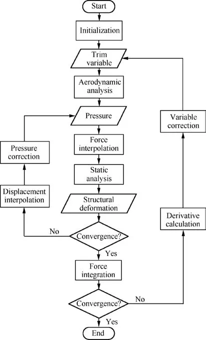
Fig.1 Calculation flowchart of static aeroelasticity analysis.
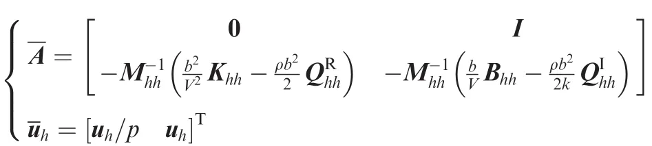
To solve Eq.(7),a certain speed is given first,and the natural frequency of the structure is calculated as the initial value of k.Then an iterative calculation is performed until k converges to the imaginary part of p.If the real part of the final convergence p is greater than zero, flutter occurs at the current speed.
2.3.Aerodynamics
A viscous/inviscid iteration method is employed to estimate the lift-to-drag ratio of a large airplane under the cruise condition with moderate flow separation.27A multigrid calculation procedure with an equally spatial Cartesian mesh is applied to discretize the governing Euler equations for inviscid compressible flow.The integral form of the Euler equation for the general control volume is written as

where F= [ρ ρu ρv ρw ρe ]Tis the dependent vector,in which u,v and w are the velocity components in the Cartesian coordinate system,and e is the internal energy of unit volume.E is the flux vector.^n is the outward normal vector.For the high subsonic cruise of a large airplane,local shock wave begins to appear,so CFD methods should be applied instead of any potential flow method.To decompose the induced drag and the shock wave drag from the total inviscid drag,far- field drag analysis is applied.28
Cartesian blocks of meshes do not require grids aligned to the body surface,which greatly facilitates grid generation.Spatial mesh deformation can be implemented effortlessly by moving the finest-level mesh according to the variation of the geometric shape.11Therefore,the solver is ideally suitable for dealing with aerodynamic/structural coupling problems.
The viscous correction method27is accomplished in use of the transpiration technique based on an inviscid compressible flow field solved by the Euler equation.The surface boundary condition is modified based upon the transpiration velocity,which is a function of the boundary layer edge velocity,the displacement thickness,and the local density.The boundary layer characteristics are computed along surface streamlines.The boundary layer correction is an iterative process that may require 3–5 viscous/inviscid cycles to complete.
The test cases of a lot of research18,19have validated the results of the viscous/inviscid iteration method to be very close to experimental data,so the method is effective and applicable.The commercial CFD solver MGAERO contains this method,and it has also been verified by many test cases.27The viscous/inviscid iteration method has already been applied in conceptual designs of large airplanes.3
2.4.Stability and control
A large airplane in steady flight may be subjected to a momentary disturbance by a nonuniform or nonstationary atmosphere,or by movements of passengers,release of stores,and so forth.They can all be regarded as a small disturbance.Based on the linear small-disturbance theory,the airplane’s equations of motion can be decoupled,and its longitudinal and lateral motions can be considered independently.The normal state-space equation29is written as

where A and B are the system matrices,x is the state vector,and u is the control vector.A and B are composed of the aerodynamic derivatives,the mass property,and the aerodynamic coefficients.x is composed of the disturbed flight parameters,and u is composed of the deflections of control surfaces.Each item of the system matrices is introduced in Ref.29,and the analytic solutions of Eq.(9)can be obtained directly by solving the linear nonhomogeneous differential equation.
Considering the elastic deformation effect,the control surface efficiency21can be expressed as
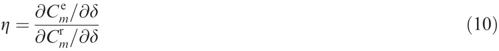
where Cmis the moment coefficient,superscripts ‘e” and ‘r”denote the elastic and rigid derivatives,respectively,and δ is the control surface deflection.
2.5.Kriging method
The quality of a surrogate model strongly depends on appropriate choices of the DoE type and the sampling size.To improve the quality of the Kriging model and reduce the sampling number,Latin hypercube DoE30is utilized to guarantee the property of space filling by maximizing the minimal distance between any two sample points.
For a problem with q response cases,the Kriging method31can express the lth unknown function yl(v)as

where v is an n-dimensional vector(n design variables),fl(v)is a regression model,and zl(v)is a random function(stochastic process).The regression models are often polynomials of orders 0,1,and 2.A linear combination of p chosen functions is used as the regression model as follows:

where βlis the regression parameter matrix,which can be determined by the generalized least squares estimation.
The random process zl(v)is assumed to have a mean of zero and a covariance of

between zl(vi)and zl(vj),whereis the process variance for the lth component of the response,viand vjare arbitrary design vectors,and R(θ,vi,vj)is the correlation model with vector θ.An interpretation of the model is that deviations from the regression model,though the response is deterministic,may resemble a sample path of a(suitably chosen)stochastic process zl(v).Many correlation models,such as the exponential function,the generalized exponential function,the Gaussian function,the linear function,the spherical function,and the cubic spline function,can be chosen for the stochastic process.A bad choice may cause the correlation matrix to be ill conditioned,22which will impair the predictive accuracy.In practical engineering problems,both the correlation function and regression model are always decided by trial and error.
The determination of the optimal correlation parameters θ is an optimization problem,and a simple but efficient algorithm with successive coordinate search and pattern moves32is applied.All of the above approaches are included in a MATLAB toolbox DACE,and more details about the Kriging method can be found in Refs.31,32
The relative error21utilized for accuracy validation is the difference between the actual response and the prediction,which is formulated as

where rais the actual response value and rpis the predicted value.
2.6.Optimization formulation
The MAO problem is to search the optimal design variables to minimize the objective function subject to the specific constraints,21which can be formulated as

where F(w)is the objective function,gj(w)are the constraints,andare the lower and upper bounds of the design variables,respectively,nconis the number of design constraints,and ndvis the number of design variables.
3.Modeling and optimization strategy
3.1.Parametric modeling
Parametric modeling is a key technology for integrated optimization.The double-spar structure shown in Fig.2 describes a common layout of the high-aspect-ratio backswept wing of a large airplane.The geometric shape of the wing can be parameterized with seven parameters,including the inboard/outboard taper ratios(ηin,ηout),the inboard/outboard aspect ratios(λin,λout),the sweep angle of the leading edge(χ),and the inboard/outboard dihedral angles(ψin,ψout).In order to maintain the conjunction with the body,the wing root length(cr) remains constant. Six independent parameters(pr1,pr2,pk1,pk2,pt1,pt2)are used to determine the positions of the front and rear spars.
3.2.Simplified plate-beam structure
Parametric modeling of a three-dimensional finite element structure is rather complicated,and limited shape and layout parameters cannot accurately describe the details of the wing structure.Varieties of simplified structural models33–35have been studied.In this paper,a simplified two dimensional plate-beam structure5,35is applied for structural parameterization.
A beam composed of two or more materials is called a composite beam,36while a beam of one material is called a homogeneous beam.The transition process of a composite beam to a homogeneous beam is shown in Fig.3.
The normal stress at these two cross sections is
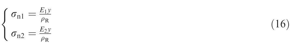
where ρRis the radius of curvature at the neutral plane,and E1and E2are the elastic modules.

Fig.2 Parametrization of a high-aspect-ratio backswept wing with a double-spar structure.

Fig.3 Transition process of a composite beam to a homogeneous beam.
There is only a bending moment at the cross section,which is formulated as
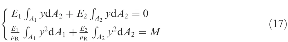
and Eq.(16)can be written as

where M is the bending moment,and I1and I2are the moments of inertia with respect to the neutral axis.The modular ratio between these two materials is defined as n=E2/E1,and the equivalent moment of inertia is defined as=I1+nI2.Eq.(18)can be written as
Therefore,the transition process of a composite beam to a homogeneous beam is achieved by enlarging(or reducing)the cross-sectional size in the z-direction with the same magnification as the modular ratio,and the neutral plane and the vertical bending stiffness can remain constant.The flange and web of the front/rear spar shown in Fig.4 as well as ribs can be transformed to an equivalent I-beam.
A typical wing box structure,in addition to spars,ribs,and stringers,includes the upper skin,the lower skin,and the interspace between the upper and lower skins,which is shown in Fig.5.The skins and interspace can be treated as a three layer composite laminate in the simplified plate-beam structure.

Fig.5 Decomposition of a wing box structure.
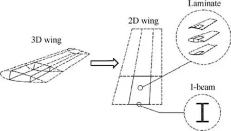
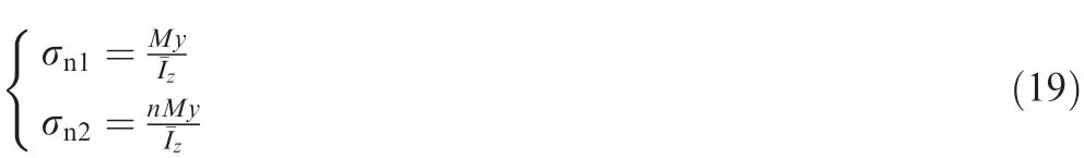
Fig.6 Simplification of a 3D wing structure.
The simplified two-dimensional plate-beam wing shown in Fig.6 has similar characteristics to those of the three dimensional wing,and it is more suitable for parametric modeling in the preliminary phase and can be transformed to a detailed structure for further designs conveniently.More details are introduced in Ref.35
3.3.Baseline models and analytical conditions
The baseline surface meshes for CFD analysis shown in Fig.7 contain a jig shape and a cruise shape.
Considering the elastic deformation of the jig shape under the cruise condition,the cruise shape is used for drag calculation.Because the magnitude of the wingtip displacement is much smaller than that of the span wise length,it is reasonable to construct the cruise shape in use of the structural deformation in the z-axis.11The in finite plate spline is employed to interpolate displacements from structural nodes to aerodynamic grids.A half of the airplane is meshed into seven levels with a total of 1637429 grids.
Fig.7 Surface meshes for CFD analysis.
The baseline surface mesh of the high-order panel method is shown in Fig.8.A half of the body surface consists of 2556 quadrilateral elements,86 triangular elements,and 4016 control points.
The simplified plate-beam wing is shown in Fig.9.
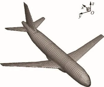
Fig.8 Surface mesh of high-order panel method.
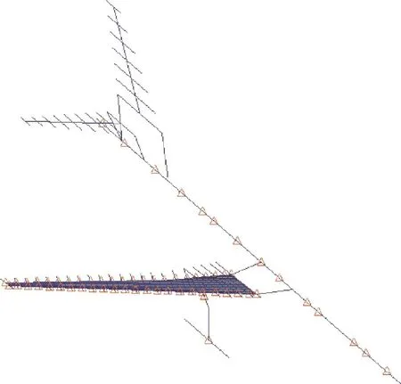
Fig.9 Simplified plate-beam wing.
The wing skin is divided into 492 quadrilateral elements and 14 triangle elements.Bar elements are utilized for the front/rear spars,stringers,and ribs.Properties of aluminium are assigned to the wing structure.The body,tail, fin,engine,and leading/trailing edges are modelled with rigid elements,and the weight except for the wing structure is represented by concentrated mass elements.The plate-beam structure is simplified from a three-dimensional finite element structure,and the structural sizes are modified slightly to ensure the same characteristics of structural dynamics.Then the simplified structure can be used in optimization.
A fixed maximum takeoff weight of 84500 kg and a cruise Mach number of 0.785 at a height of 11200 m are applied to perform the analysis.The Reynolds number is 5.71×10⁶based on the mean aerodynamic chord.The root chord remains a constant length of 6.17 m,and the reference area is varied with geometric parameters.
The baseline models are the optimized results of conventional sequential optimization with the same analytical methods,conditions,and constraints.To ensure all the specific constraints,several iterations have to be performed between the aerodynamics and structure.
3.4.Optimization strategy
Fig.10 describes the distributions of the cross-sectional area of the front/rear spar flange and those of the upper/lower wing skin thickness.The wing is divided into twelve regions along the spanwise direction.The sectional area of the spar flange and the skin thickness increase from the wing tip to the wing kink,whereas they decrease from the wing kink to the wing root.The inboard skins are divided into three regions along the chordwise direction,and they decrease from the trailing edge to the leading edge.The structural sizes can be described by sixty parameters.
The objective function is to minimize the structural weight,and constraints are given as follows:
(1)The flutter speed at the sea level is greater than 320 m/s.
(2)The maximum torsion at the wing tip is less than 2.14°.This constraint will restrict elastic torsional deformation that might lead to a decrease of the local angle of attack.
(3)The maximum vertical displacement at the wing tip is less than 7%of the magnitude at the semi-span.The constraint guarantees that the wing deformation of the large airplane will still obey the linear theory of elasticity under the cruise flight condition.
(4)The aileron efficiency is greater than 60%.
(5)The total drag is less than the baseline drag.

Fig.10 Distributions of spar flange cross-sectional area and wing skin thickness.
Therefore,for the preliminary design of a large airplane,integrated optimization is performed to minimize the wing structure weight using 73 independent design variables(7 geometric parameters,6 spar position parameters,and 60 structural size parameters)and 5 constraints.
3.5.Optimization flowchart
Fig.11 describes the optimization flowchart of the GA process.
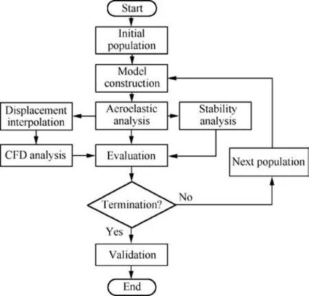
Fig.11 Optimization flowchart of GA.
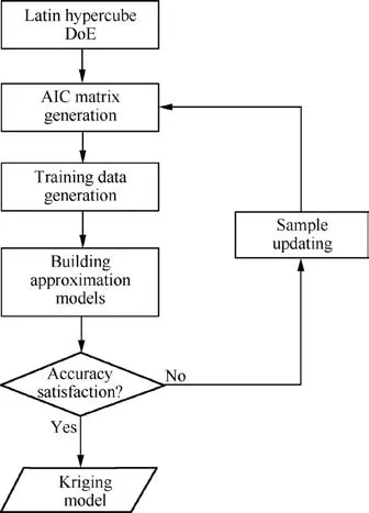
Fig.12 Construction of a Kriging model.
GA-based optimization is performed to seek the optimal design of a large airplane.The responses of aerodynamics,structure,and stability are analysed to evaluate the individuals generated by GA.The maximum generation number is 15,and the individual number of each generation is 1000.For static aeroelasticity analysis,AIC matrices should be updated when the aerodynamic shape varies.However,the computational burden is unacceptable when using PANAIR to generate the AIC matrices of all individuals in the optimization process.To solve the problem,the Kriging method is employed to predict parameterized AIC matrices,so the optimal solution should be validated by the AIC matrices generated by PANAIR to obtain all the actual responses.
Two hundred samples with the AIC matrices of different aerodynamic shapes are selected using Latin hypercube DoE to construct a Kriging model.To validate the accuracy of the Kriging model,another 30 sampling points are computed.If the accuracy is not satisfying,the samples will be updated to reconstruct the Kriging model.The flowchart is shown in Fig.12.
4.Result analysis
4.1.Construction and validation of Kriging model
The quadratic regression(2-order polynomial)is used as the regression model by comparing the predicted results of different regression models as

According to the definition p=0.5(n+1)(n+2)and the number of the geometric parameters(n=7),36 functions are determined.The Gaussian function is used as the correlation model,and the correlation parameters are optimized by the method provided by DACE.Because of the good linear characteristics between the AIC matrices and the aerodynamic shapes,the correlation parameters are all very large,which helps the Kriging model have relatively well conditioned correlation matrices.
The AIC matrices have 26738528 items in total,and each item is regarded as a response case.To verify the accuracy of the Kriging model used for AIC matrix prediction,the relative errors of the static aeroelasticity responses are calculated,which describe the accuracy more easily and directly.Fig.13 shows the relative errors of the wingtip torsion,wingtip deformation,and aileron efficiency.
The average errors of the wingtip torsion,wingtip deformation,and aileron efficiency are 1.33%,0.97%,and 0.76%,respectively,which satisfy the engineering requirements and can be used for AIC matrix prediction.
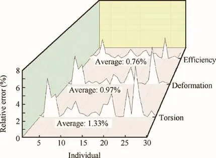
Fig.13 Accuracy of Kriging model used for AIC matrix prediction.
4.2.Response analysis and comparison
GA-based optimization is performed to seek the optimal design.Integrated optimization takes about 40 days using parallel computing on personal computers,while conventional optimization needs nearly 3 months to obtain appropriate design parameters.
The response comparison is listed in Table 1.The responses of the optimal model are shown in column ‘Integrated”,and those of the baseline model in column ‘Baseline”.In column‘Structural” is the responses of structural optimization without the drag constraint and aerodynamic shape parameters,and the drag of the optimized solution is calculated as the validation.All the responses are the validated responses using the AIC matrices generated by PANAIR.
Compared with the baseline model,the wing structure weight of the optimal model can be reduced much while satisfying all the given constraints,which demonstrates that the integrated optimization method is effective.
Structural optimization could obtain a lighter wing structure weight,while its drag does not satisfy the given constraint,and therefore,iterations between the aerodynamics and structure have to be carried out.If structural optimization is performed considering the aerodynamic constraint,a solution may be obtained,while aerodynamic performance cannot be improved without the aerodynamic shape parameters,and the design potential is not exploited adequately.Repeatedadjustments of the aerodynamic and structural parameters will finally result in a long design period and a low efficiency.

Table 2 Geometric parameters and spar position parameters.
MAO techniques improve upon the obtained solutions compared to classical sequential designs in terms of the given constraints,as they account for all interactions and influences between the disciplines of aerodynamics,structure,and stability,and all the design parameters can be obtained simultaneously.MAO techniques can avoid an iterative design and improve the efficiency.Compared with conventional optimization,MAO can reduce a design period for more than 50%with the same analytical methods and conditions,and accuracy can also be guaranteed.
Table 2 lists the seven geometric parameters and six spar position parameters of the jig shapes.
A comparison of the cruise shapes is shown in Fig.14.
The most apparent differences between the cruise shapes are that the optimal shape has a larger sweep angle of the leading edge.An increase of the sweep angle results in enhancing the bending and torsion coupling of the wing structure,which causes increases of torsion and displacement.On the other hand,an increase of the sweep angle contributes to reducing the local shock wave drag.The local shock wave drag is the most significant flight drag of a large airplane under the cruise Mach number of 0.785.Fig.15 describes the comparison of the local Mach number between the optimal cruise shape and the baseline cruise shape.
It is seen that the optimal shape has a smaller area of the supersonic region than that of the baseline shape,which can help to reduce the local shock wave drag.
The pressure distributions of cruise shapes are compared.Fig.16 shows the airfoil pressure distributions at 20%and 40%span sections and the upper surface pressure contours.Fig.17 shows the airfoil pressure distributions at 60%and 80%span sections and the lower surface pressure contours.

Fig.14 Comparison of cruise shapes.

Fig.15 Local Mach number distributions of upper wing surfaces.
A change of the wing geometry shape has a significant influence on the pressure distributions of the wing surface and the region nearby,but has little effect on the other regions.The optimal wing has a smoother chordwise variation of the pressure distribution,which helps reducing the drag while ensuring enough lift.A little nonsmoothness of the pressure distribution at the wingspan sections is caused by nonuniform deformation of the skins.
4.3.Stability and control analyses
The longitudinal stability of flight dynamics is studied.The needed geometric and aerodynamic data considering the elastic effect is computed to construct the system matrices A and B.The state vector x is composed of the perturbation velocity ΔV,the perturbation angle of attack Δα,the perturbation pitch rate Δq,and the perturbation pitch angle Δθ.The forth-order model is utilized.The transient characteristics of the state variables for longitudinal motion without the control force are shown in Fig.18.
The disturbance quantities ultimately vanish,and they all represent stable modes.The natural modes have two damped oscillations,one of long period and lightly damped(phugoid mode:Fig.18(a)and(d)),while the other of short period and heavily damped(short-period mode:Fig.18(b)and(c)).The short-period mode has a very strong stability and can converge with little or no oscillation,and the stability of uncontrolled motion is guaranteed in the optimization process.The response of a large airplane to a sudden movement of the elevator is shown by the step response.Time traces of the state variables with an elevator deflection of one degree(Δδe=1°)are shown in Fig.19.
It is seen that the angle of attack and the pitch rate respond quickly to the elevator motion,and that their variations are dominated by the rapid,well-damped short-period mode.By contrast,the velocity and the pitch angle respond more slowly.The steady state that is approached so slowly has a slightly higher velocity and a slightly smaller angle of attack than those in the original flight condition,and both of the changes are expected from a down movement of the elevator.The baseline model is more sensitive to the elevator deflection,and the state variables can be more easily changed.
The lateral stabilities of flight dynamics are studied.The needed geometric and aerodynamic data considering the elastic effect is computed to construct the system matrices A and B.The state vector x is composed of the side angle β,the roll rate p,the yaw rate r,and the roll angle φ.The forth-order model is utilized.The transient characteristics of the state variables for longitudinal motion without the control force are shown in Fig.20.
It is seen that the side angle,the roll rate,and the yaw rate ultimately vanish.The roll angle changes to a constant value ultimately.Figs.21 and 22 show the time traces of the state variables with an aileron deflection of one degree(Δδa=1°)and a rudder deflection of one degree(Δδr=1°),respectively.
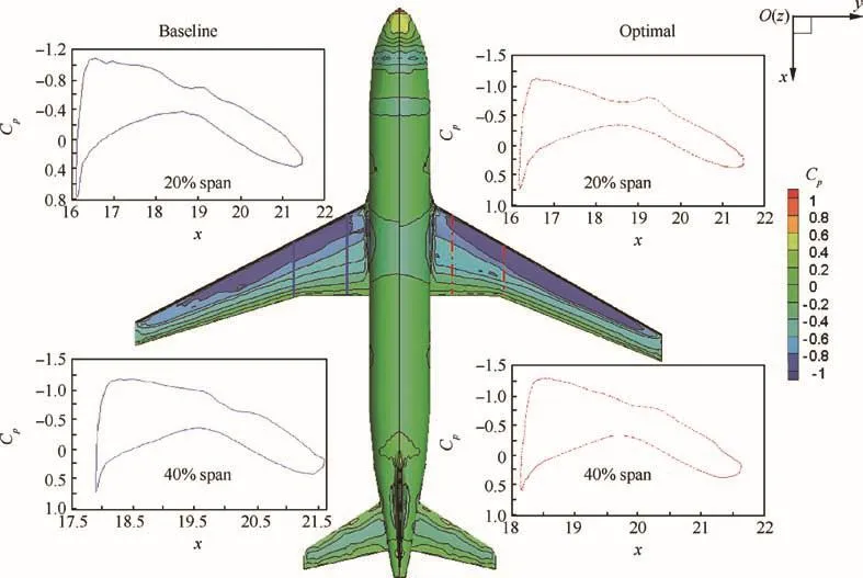
Fig.16 Pressure distributions at 20%and 40%span sections and upper surface pressure contours.

Fig.17 Pressure distributions at 60%and 80%span sections and lower surface pressure contours.
It is seen that the state variables can respond to the control surfaces quickly.Unlike the elevator,the lateral controls,i.e.,the aileron and the rudder,are not used individually to produce changes in the steady state.This is because the steady state values(β,p,r,φ)that result from a constant δaor δrare not generally of interest as a useful flight condition.Clearly,the control of a large airplane,whether by a human or an automatic pilot,demands a more sophisticated control activity than simply moving one control surface to its new position.
The required dynamic behavior is ensured by making the small-disturbance properties of concern such that the control can keep the disturbance to an acceptably small level,and it should be taken into account in the MAO of a large airplane.
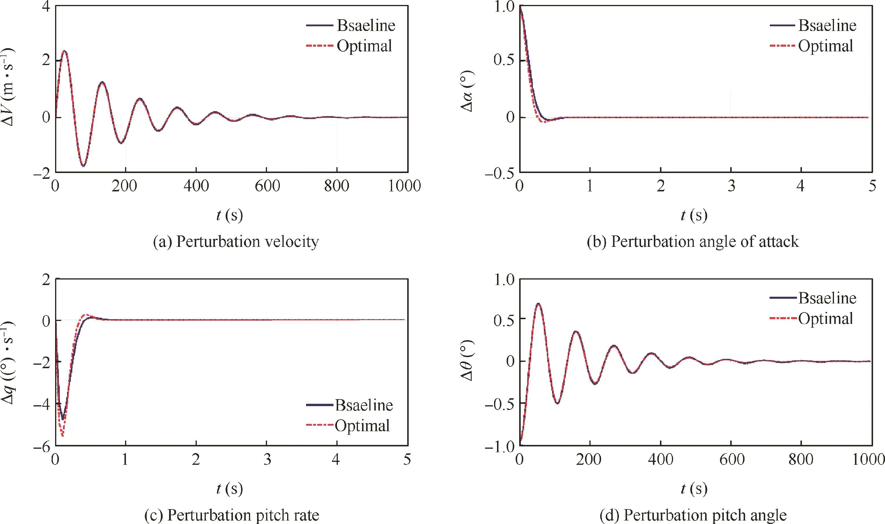
Fig.18 Transient characteristics of state variable for longitudinal motion without control force.

Fig.19 Time traces of state variables with Δδe=1°.
4.4.Sensitivity analysis
Considering the multi modality of MAO problems,only the sensitivity of the optimal design is analyzed.The derivatives of the responses with respect to the variation of each design variable are calculated by the finite difference method.In order to unify the units of different design variables,the variation of each design variable is 5%of its design interval,so the importance of different parameters can be compared.The flutter occurrence is determined by additional damping at a certain speed,so the sensitivity analysis of the flutter speed is not taken into account.The sensitivity analyses of the weight,wingtip torsion,wingtip displacement,aileron efficiency,and drag are conducted,and results are shown in Fig.23.
The more important a design variable is to the response,the larger the corresponding area is in the pie chart.DV1 to DV7 are the geometric parameters of the inboard/outboard taper ratios,the inboard/outboard aspect ratios,the sweep angle of the leading edge,and the inboard/outboard dihedral angles,respectively.DV8 to DV10 are the parameters of the front spar positions at the wing root,the wing tip,and the wing kink,respectively.DV11 to DV13 are the parameters of the rear spar positions at the wing root,the wing tip,and the wing kink,respectively.DV14 is the upper skin thickness.DV15 is the lower skin thickness.DV16 is the cross-sectional area of the front spar flange.DV17 is the cross-sectional area of the rear spar flange.Symbol‘-” means a negative correlation.

Fig.21 Time traces of state variables with Δδa=1°.
The results show that an appropriate increase of the inboard taper ratio helps to reduce the structural weight.The outboard aspect ratio,sweep angle of the leading edge,and skin thickness have great influences on the other responses,and they should be paid more attention in the preliminary design of a large airplane.It should be noted that MAO accounts for the interactions and influences between different disciplines,so multi modality is obvious,and the derivative might even be opposite to what only considers a single discipline.
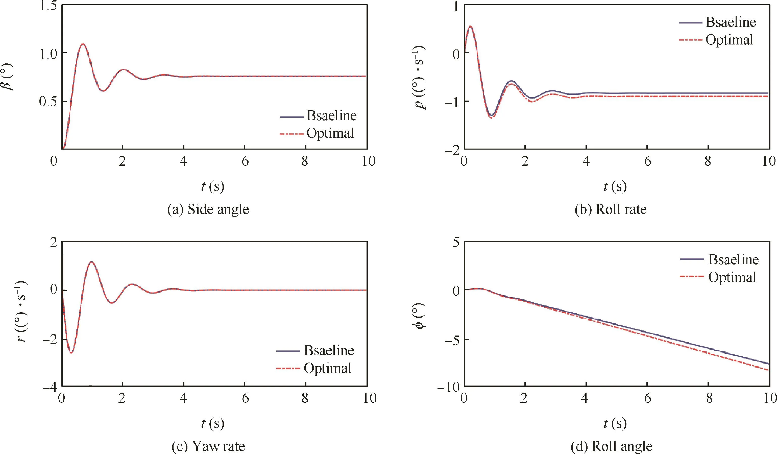
Fig.22 Time traces of state variables with Δδr=1°.
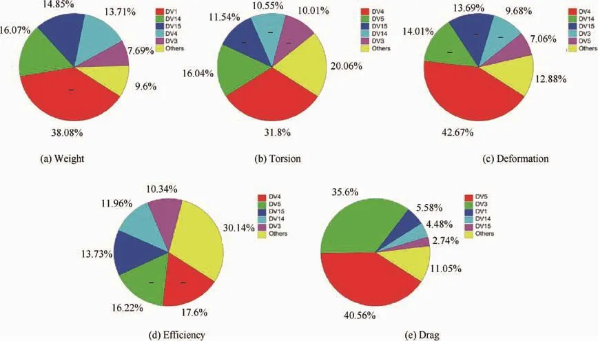
Fig.23 Sensitivity of optimal design.
5.Conclusions
An integrated optimization method for the preliminary design of a large airplane is presented.
(1)A simplified plate-beam wing structure is optimized to seek the minimum structural weight subject to aerodynamic,aeroelastic,and stability constraints,and the optimal wing geometry shape,front/rear spar positions,and structural sizes can be obtained simultaneously.
(2)The three-dimensional flight load analysis,the viscous/inviscid iteration,and the linear small-disturbance theory guarantee both efficiency and accuracy.Besides,the AIC matrices utilized in the static aeroelasticity analysis are predicted by the Kriging method,which can further improve the optimization efficiency.
(3)MAO techniques contribute to a wing weight reduction greatly compared with classical sequential design in terms of given constraints,as they account for all interactions and influences between the disciplines of aerodynamics,structure,and stability simultaneously.The integrated optimization avoids the iterative design process between different disciplines,and the design efficiency as well as the overall performance of a large airplane can be greatly improved.The integrated optimization exploits the enormous design potential of the preliminary phase,and it will be widely applied for modern airplane design.
(4)Sensitivity analysis results demonstrate that the outboard aspect ratio,sweep angle of the leading edge,and skin thickness have significant influences on the overall performance of a large airplane,and they should be paid more attention in a design.Multimodality is obvious for the MAO of a large airplane design in the preliminary phase,and the derivative may even be opposite to what only considers a single discipline.
The results obtained from the integrated optimization provide designers with a wealth of information in the preliminary phase and are important references for further design.A multidisciplinary optimization study of aerodynamics/structure/stability for a large airplane in a detailed design phase has already been performed.
Acknowledgements
This work was supported by the National Key Research and DevelopmentProgram (No.2016YFB0200703)andthe Academic Excellence Foundation of Beihang University for Ph.D.Students.
1.Lyu Z,Martins JRRA.Aerodynamic shape optimization of an adaptive morphing trailing-edge wing.J Aircraft2015;52(6):1951–70.
2.Hoogervorst JEK,Elham A.Wing aerostructural optimization using the individual discipline feasible architecture.Aerosp Sci Technol 2017;65:90–9.
3.Wan ZQ,Wang XZ,Yang C.Integrated aerodynamics/structure/stability optimization of large aircraft in conceptual design.PIMech Eng G-J Aer 2017.https://doi.org/10.1177/0954410016687143.
4.Gu SF,Xie SS.Aircraft design.Beijing:Beihang University Press;2001.p.2–4[Chinese].
5.Wan ZQ,Zhang BC,Du ZL,Yang C.Aeroelastic two-level optimization for preliminary design of wing structures considering robust constraints.Chin J Aeronaut 2014;27(2):259–65.
6.Lu WS,Tian Y,Liu PQ.Aerodynamic optimization and mechanism design of flexible variable camber trailing-edge flap.Chin J Aeronaut 2017;30(3):988–1003.
7.Boulkeraa T,Ghenaiet A,Mendez S,Mohammadi B.A numerical optimization chain combining computational fluid dynamics and surrogate analysis for the aerodynamic design of airfoils.P I Mech Eng G-J Aer 2014;228(11):1964–81.
8.Wan ZQ,Liu DY,Tang CH,Yang C.Studies on the influence of spar position on aeroelastic optimization of a large aircraft wing.Sci China Technol Sc 2012;55(1):117–24.
9.Liang L,Wan ZQ,Yang C.Aeroelastic optimization on composite skins of large aircraft wings.Sci China Technol Sc 2012;55(4):1078–85.
10.Wan ZQ,Xiao ZP,Yang C.Robust design optimization of flexible backswept wings with structural uncertainties.J Aircraft 2011;48(5):1806–9.
11.Wan ZQ,Liang L,Yang C.Method of the jig shape design for a flexible wing.J Aircraft 2014;51(1):327–30.
12.Yang GW,Chen DW,Cui K.Response surface technique for static aeroelastic optimization on a high-aspect-ratio wing.J Aircraft 2009;46(4):1444–50.
13.Zhang KS,Han ZH,Li WJ,Song WP.Coupled aerodynamic/structural optimization of a subsonic transport wing using a surrogate model.J Aircraft 2008;45(6):2167–70.
14.Mastroddi F,Gemma S.Analysis of Pareto frontiers for multidisciplinary design optimization of aircraft.Aerosp Sci Technol 2013;28(1):40–55.
15.MSC Software Corporation.MSC Nastran Version 68:aeroelastic analysis user’s guide.Newport Beach:MSC Software Corporation;2014.
16.ZONA Technology,Inc.ZONAIR user’s manual Version 4.4.Scottsdale:ZONA Technology,Inc.;2010.
17.Liu YZ,Zhu SY,Wan ZQ,Yang C.A high efficiency aeroelastic analysis method based on rigid external aerodynamic force and elastic correction by high-order panel method.55th AIAA aerospace sciences meeting;2017 Jan 9–13;Grapevine,USA.Reston:AIAA;2017.
18.Zhu ZQ,Ma X.An inverse integral 3D compressible boundary layer method and coupling with transonic inviscid solution.Acta Mech 1991;89(1):187–208.
19.Sekar WK,Laschka B.Calculation of the transonic dip of airfoils using viscous-inviscid aerodynamic interaction method.Aerosp Sci Technol 2005;9(8):661–71.
20.Timme S,Marques S,Badcock KJ.Transonic aeroelastic stability analysis using a kriging-based schur complement formulation.AIAA J 2011;49(6):1202–13.
21.Wan ZQ,Wang XZ,Yang C.A highly efficient aeroelastic optimization method based on a surrogate model.Int J Aeronaut Space 2016;17(4):491–500.
22.Sacks J,Welch WJ,Mitchell TJ,Wynn HP.Design and analysis of computer experiments.Stat Sci 1989;4(4):409–35.
23.Choi WH,Kim JM,Park GJ.Comparison study of some commercial structural optimization software systems.Struct Multidiscip Optim 2016;54(3):685–99.
24.Manan A,Vio GA,Harmin MY,Cooper JE.Optimization of aeroelastic composite structures using evolutionary algorithms.Eng Optimiz 2010;42(2):171–84.
25.Kouh JS,Suen JB.A 3D potential-based and desingularized high order panel method.Ocean Eng 2001;28:1499–516.
26.Harder RL,Desmarais RN.Interpolation using surface splines.J Aircraft 1972;9(2):189–91.
27.Analytical Methods,Inc.MGAERO user’s manual Version 3.5.Redmond:Analytical Methods,Inc;2010.
28.van Dam CP,Nikfetrat K,Wong K,Vijgen PMHW.Drag prediction at subsonic and transonic speeds using Euler methods.J Aircraft 1995;32(4):839–45.
29.Fang ZP,Chen WC,Zhang SG.Flight dynamics of aircraft.Beijing:Beihang University Press;2005.p.288–346[Chinese].
30.The MathWorks,Inc.MATLAB statistic toolbox user’s guide R2014b.Natick:The MathWorks,Inc.;2014.
31.Lophaven SN,Nielsen HB,Søndergaard J.DACE—A MATLAB kriging toolbox Version 2.0.Copenhagen:Technical University of Denmark;2002.Report No.:IMM-TR-2002-12.
32.Lophaven SN,Nielsen HB,Søndergaard J.Aspects of the MATLAB toolbox DACE.Copenhagen:Technical University of Denmark;2002.Report No.:IMM-REP-2002-13.
33.Vepa R.Aeroelastic analysis of wing structures using equivalent plate models.AIAA J 2008;46(5):1216–25.
34.Elsayed MSA,Sedaghati R,Abdo M.Accurate stick model development for static analysis of complex aircraft wing-box structures.AIAA J 2009;47(9):2063–75.
35.Zhang BC.Methods for aeroelastic optimization in the preliminary stage of aircraft design[dissertation].Beijing:Beihang University;2011.p.63–70[Chinese].
36.Shan HZ.Mechanics of materials II.Beijing:Beihang University Press;2010.p.14–7[Chinese].
杂志排行

CHINESE JOURNAL OF AERONAUTICS的其它文章
- An efficient aerodynamic shape optimization of blended wing body UAV using multi- fidelity models
- Effect of multiple rings on side force over an ogive-cylinder body at subsonic speed
- Dynamic temperature prediction of electronic equipment under high altitude long endurance conditions
- Experimental investigation on static/dynamic characteristics of a fast-response pressure sensitive paint
- Takagi-Sugeno fuzzy model identification for turbofan aero-engines with guaranteed stability
- Experimental study on film cooling performance of imperfect holes