Mechanism of stall and surge in a centrifugal compressor with a variable vaned diffuser
2018-06-28XiangXUETongWANGTongtongZHANGBoYANG
Xiang XUE,Tong WANG,Tongtong ZHANG,Bo YANG
Gas Turbine Research Institute,Shanghai Jiao Tong University,Shanghai 200240,China
1.Introduction
A centrifugal compressor is often used as the core component of a turbocharger or air conditioning system,which is regarded as an indispensable fluid machine in the industrial production.Compared with an axial compressor,a centrifugal compressor has some advantages,such as single-stage high pressure ratio,compact structure,light weight,and so on.With the increasing demand for high performance,manufacturers need to design more complex compressor components with wider operating ranges.The flow instability at low flow rates can lead to a high aerodynamic loss and even structural damage.It is therefore important for in-depth understanding of the mechanisms that lead to unstable flow behaviors in centrifugal compressors.
Generally,there are two different kinds of unstable flow behaviors which can lead to stall.One is the modal-type wave which has a long wave length and its traveling speed is about 20%–50%of the impeller rotating speed.1The other is the spike-type wave with a short wave length.The specific kinds of operating conditions which are known to trigger the twotypes of waves have been analyzed by Day.2The spike-type disturbance wave was firstly discovered in a turbocharger compressor by Spakovszky and Roduner.3However,it is yet to be determined which one of the two kinds of stall waves would occur prior to stall in different situations.
With regards to surge,it is divided into two different types,which are mild surge and deep surge,based on the pulsation amplitude of dynamic parameters and whether back flow occurs or not.4–6In general,when mild surge occurs,the signal of dynamic parameters,such as pressure and velocity,is approximately sinusoidal and oscillates slightly at the Helmholtz frequency.This frequency is considered to be related to the entire compressor system,which is generally within the range of 5–15 Hz.7Meanwhile,deep surge always occurs more suddenly and coincides with obvious back flow.However,apart from these qualitative descriptions,more quantitative descriptions should be proposed to distinguish between these two typical surge modes.In this way,the two modes can be better defined.
Much theoretical derivation about the mechanism of flow instability generation has been conducted.It has been considered by most early researchers that the transition from one unstable mode to another is associated with a specific operating condition.For example,when the leakage flow is too large in a single-stage axial compressor,both spike wave and modal wave occur prior to stall.The form of stall inceptions varies with different operating conditions.2A lumped parameter model was established by Greitzer.8Based on the assumption of fluid inertia,the model explains the mechanism of suction and exhaust in axial compressors during surge.Meanwhile,a dimensionless lumped parameter B was presented for describing the compressor behavior at low flow rates.9It can determine the mode of instability.However,it ignores some detailed flow structures in the impeller,such as leakage flow,and is usually not used in the case of centrifugal compressors.The theoretical model was improved by Spakovszky,10which can be used on centrifugal compressors.In the new model,the interaction between the impeller and the diffuser vane is focused on.Among recent research,it has been suggested that the occurrence of leading edge stall in the impeller is a necessary part of mild surge,and the diffuser stall always indicates deep surge.At high rotating speeds,mild surge causes the diffuser stall,which triggers deep surge in turn.11Some special unstable flow modes,such as mild surge and deep surge,at different rotating speeds were obtained in a centrifugal compressor by Zheng et al.12The effect of volute was paid attention to in their experiments.Moreover,the influence of the diffuser vane setting angle on performance characteristics was researched by Tamaki.13The standard deviation of measured data can be used as an indicator to determine precisely when a centrifugal compressor suffers surge.14In addition,the hysteresis during the compressor’s return to the stable condition from the stall or surge point should also be taken into consideration.When the system returns to the stable operating state,the pressure ratio is not a single-valued function based on the flow rate any more.It is related to the whole adjusting process,which shows the nonlinear characteristic of the compressor system.A lot of data about the hysteresis in a multistage compressor system was used to obtain compressor characteristics during surge.15
According to these previous experimental investigations,research on the mechanism of flow instability has been promoted in recent years,since innovations continuously occurred in many aspects,such as measuring method,data processing,theoretical derivation,and so on.However,most of the works have been done in compressors with vaneless diffusers,while compressors with vaned diffusers have rarely been investigated experimentally,especially those with variable vaned diffusers.A compressor with a variable vaned diffuser can better cope with variable operating conditions.In addition,the influence of the diffuser vane angle has always been neglected.Thus,it is important to obtain more details about stall and surge in this kind of compressor.In addition,most experimental studies have focused on the behavior of stall or surge inceptions in the circumferential direction,but ignored the differences between the signals at some specific radial locations,especially those in the impeller.In this paper,an experimental study on the mechanism of stall and surge in a centrifugal compressor with a variable vaned diffuser is carried out.The features of stall and surge at different diffuser vane angles are presented,and various modes of compressor instability are defined,such as stall,mild surge,and deep surge.The effects of different diffuser vane angles on the transformation from stall to deep surge are analyzed and discussed.
2.Test facility and instruments
The experiment is based on a centrifugal compressor with a variable vaned diffuser,which is industrially used in sewage treatment systems.The main parameters of the tested compressor are shown in Table 1.The diffuser vane angle(OGV)can be adjusted from –12°to 12°.
2.1.Performance test system
The schematic diagram of the performance test system is shown in Fig.1.The compressor is driven by an electric motor of 90 kW,and the rotating speed is increased by using a gear box.Air is drawn into the compressor from the atmosphere and then discharged into the outlet silencer channel.The flow rate is regulated by adjusting the throttle valve equipped on the outlet duct.Both the inlet and outlet pressures are measured by a U-tube manometer with an absolute error within±0.26 kPa.Both the inlet and outlet temperatures are measured by a thermocouple with an absolute error within±1.5°C.A Venturi meter with an absolute error within±0.064 kg/s is placed on the outlet duct.The specific installation loca-tions of these measuring instruments can be seen in Fig.1,where some specific sizes are given in multiples of the inlet pipe diameter(d).
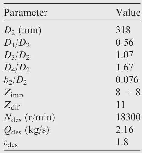
Table 1 Main parameters of centrifugal compressor.

Fig.1 Sketch of performance test system.
2.2.Dynamic test system
Sixteen Kulite fast-response dynamic pressure transducers(XCE-093)are mounted on the casing surface in the compressor,as shown in Fig.2.These dynamic pressure transducers are mounted at different radial locations along the stream direction,including the impeller region,the vaneless region,and the vaned diffuser throat region.At almost each radial location,two transducers are placed circumferentially in case one of them has a problem,and four transducers are mounted circumferentially in the vaneless region marked as 5.According to the photo on the right side of Fig.2,the tested compressor is with an asymmetric volute.The position relationship between the dynamic measuring region and the volute is shown.In addition,two dynamic pressure transducers are mounted on the inlet and outlet ducts,respectively.The measuring range of these transducers is about 0–300 kPa.
The data of these dynamic pressure transducers is recorded synchronously by a PCI-9215 acquisition card.The precision of the dynamic pressure measurement is about 1.5 kPa.To verify the accuracy of the experiment,the sampling frequency of each channel is set to 20 kHz so that the Blade Passing Frequency(BPF=2440,4880 Hz)can be captured.Note that because the impeller blades include 8 full-length blades and 8 splitter blades,the BPF is 2440 Hz at the impeller inlet area while 4880 Hz at other areas.Before the experiment,the dynamic pressure test system has been well calibrated.
Although pressure data cannot be as intuitive as velocity data,pressure transducers are easier to install on the rotating parts of compressors for analysis of internal flow structures,and the features of stall or surge in compressors can also be clearly captured.Due to leakage flow,reflux,and flow separation occurring at the tip clearance,an unstable flow always originates near the tip prior to stall.16,17The transducers are all mounted on the casing surface near the tip clearance,so that the unstable flow prior to stall or surge can be captured.
2.3.Pretreatment of dynamic signals
Since these dynamic transducers are equipped with post-signal amplifiers,the signal-to-noise ratio is greatly improved.However,some noises,such as electro-magnetic disturbances,which are caused by the motor and the inverter,still exist in the experiment.Therefore,it is necessary to filter original signals to reduce noises.For example,at a low flow rate,the Fast Fourier Transformation(FFT)result of the original signal at the impeller inlet is shown in Fig.3,where the ordinate represents Power Spectral Density(PSD).
According to Fig.3,in addition to the BPF and its multiplier,some relatively low-frequency components around the rotational frequency(fr=305 Hz)are clearly captured,which are related to the unstable flow.To focus on the signals of these frequency components in the time domain,low-pass filtering is used to filter out BPF-related signals and few highfrequency disturbances.The low-pass filter threshold is set to 2000 Hz,and a comparison between the original pressure signal and the filtered signal at position 1-1 is shown in Fig.4.nals at flow rates below 0.85Qdesare recorded during the dynamic test.
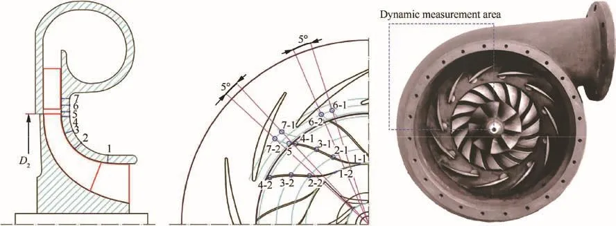
Fig.2 Layout of dynamic pressure transducers.

Fig.3 FFT result of original signal at a low flow rate.

Fig.4 Comparison between original signal and filtered signal.

Fig.5 Compressor performance map under OGV=0°.
The pressure ratio curves under five specific diffuser vane angles are shown in Fig.6.Both the surge line and hysteresis are also shown.The surge line is the broken line that connects the surge points under each diffuser vane angle.The hollow points and dashed lines represent the process of gradually recovering from unstable operating conditions.When the diffuser vane angle is adjusted positively,the air flow incidence angle at the diffuser inlet increases.Thus,surge occurs at a lower flow rate.Through low-pass filtering,the precision of the dynamic pressure measurement can be improved to 0.5 kPa.
3.Results and analysis
3.1.Performance test results
The compressor performance map under OGV=0°can be seen in Fig.5.The polytropic efficiency reaches its maximum value at the design condition.The total to static pressure ratio increases along with the flow rate decreasing,until Q/Qdesreduces to 0.76.The occurrence of stall always coincides with the peak of rising pressure ratio.14The dynamic pressure sig-

Fig.6 Total to static pressure ratio curves under different diffuser vane angles.
3.2.De finitions of two typical surge modes
As shown in Fig.7,the back-pressure is in the form of a stepped rise due to the intermittent closure of the outlet throttle valve.The back-pressure curve is obtained by reading the dynamic pressure data at the outlet duct every two seconds.The six operating conditions from I to VI are the six successive stages in the flow reduction process,and a surge occurs obviously at the operating point d3.In Fig.7,the abscissa means the number of impeller revolutions.A zero of the abscissa represents the moment of surge occurring,and negative values represents the time prior to surge.In the experiment,when the compressor enters the operating condition d3from VI by adjusting the outlet throttle,the compressor will suffer surge due to the deterioration of the internal flow field.In this case,the back-pressure will be reduced during surge.However,the back-pressure suffers a small reduction and then rebounds,followed by a sudden large drop.This phenomenon has reoccurred during repeated experiments where two different typical surge modes occur sequentially at the surge point,which are mild surge and deep surge.
Combining surface appearances with dynamic pressure signals at some specific radial locations,these two typical surge modes can be distinguished in detail.During mild surge,the liquid column of the U-tube fluctuates slightly,and the vibration of the ducts is visible.The dynamic pressure signals at the impeller inlet,diffuser inlet,and outlet duct are all approximate sinusoidal vibrations with small amplitudes.On the contrary,during deep surge,the liquid column rises and falls violently.The backpressure drops sharply accompanied by approximate sinusoidal vibration with a large amplitude,and a noticeable periodic noise caused by the back flow could be heard clearly.In addition,the pressure fluctuation patterns at the impeller inlet and diffuser inlet indicate the occurrence of reflux.14According to Fig.7,the amplitude of the pressure fluctuation at each position is significantly increased during deep surge,compared with that during mild surge.The level of the amplitude increasing at each radial location will be discussed later,which can also serve as an important quantitative indicator of the distinction between mild surge and deep surge.Based on these differences,the two different modes of surge are defined.Once deep surge occurs,the outlet valve will be turned up immediately to recover from the unstable condition to prevent serious accidents.
3.2.1.Mild surge
Under OGV=0°,the pressure signals at each radial location during mild surge at the operating condition point d3are shown in Fig.8.Mild surge occurs prior to deep surge.
The Helmholtz frequency is always considered as the mild surge dominant frequency.18Thus,the Helmholtz frequency of this compression system is very important,and can be calculated based on certain parameters considering the following formula:
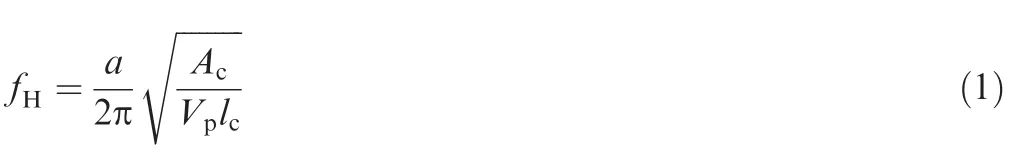
where according to Ref.12,Acand lcare the equivalent crosssectional area and length of the duct channels,respectively,and Vpis the volume of the plenum.
Since the exit total temperature during the experiment is 381.75 K,the speed of sound(a)is 391.4 m/s.Other geometric parameters are shown in Table 2,in which 680.5 is taken as the value of lc/Acand 0.3 is taken as the value of Vp.
The Helmholtz frequency of the compression system is calculated to be 4.3 Hz,which is very close to the mild surge dominant frequency.The frequency can also be clearly captured in the spectrum of these dynamic signals during mild surge.In this experiment,the dominant frequency of mild surge is slightly higher than that of deep surge.In Ref.15,the calculated Helmholtz frequency approximates the dominant frequency tested during mild surge,which is higher than that during deep surge.It is consistent with the result of this experiment.
When the ordinate of the dynamic signals during mild surge in Fig.7 is amplified,periodic pulsations with frequencies of fr/3 and 3frcan be seen in Fig.8,which are considered as stall waves.Since these transducers are not completely at the same circumferential position,these signals in Fig.8 have been phase-converted,corresponding to the case at the same circumferential position.Such dynamic pressure signals in Fig.8 illustrate that surge and stall occur alternately in the compressor,which is similar to the result in Ref.13Both a high-frequency stall wave with 3frand a low-frequency stall wave with fr/3 canbe captured in the impeller,while the form of stall in the diffuser is only a low-frequency stall.It is very noteworthy that the pressure fluctuation mode in the impeller is significantly different from that in the diffuser during mild surge.

Fig.7 Characteristics of two typical surge modes.
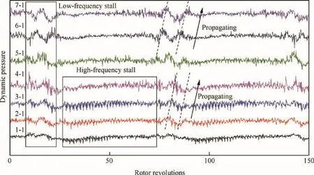
Fig.8 Pressure signals at different radial locations during mild surge under OGV=0°.
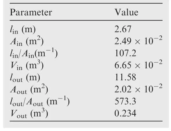
Table 2 Geometric parameters of compression system.
The pressure signals at four circumferential locations at this condition point are shown in Fig.9.According to these circumferential pressure signals in the vaneless region between the impeller and the diffuser,the stall wave propagates in the opposite direction of the impeller rotation,which is shown in the upper right corner of Fig.9.The stall wave propagates in a counterclockwise direction,just in the opposite direction of the impeller rotation.The propagating speed is calculated as 1/3 of the impeller rotating speed based on the phase difference.However,according to the radial pressure signals shown in Fig.8,the stall wave also propagates in the flow direction.These propagation directions are mainly determined by the corresponding crests and troughs of the dynamic signals at adjacent locations.Especially for the low-frequency stall wave with fr/3,this correspondence is easy to be observed,since this low-frequency stall wave always occurs intermittently and has a relatively long period.In addition,it can be seen clearly that the high-frequency stall does not occur in the vaneless region during mild surge,even if it has occurred throughout the impeller.In most of the previous literature,3it is considered that a stall wave always originates in the vaneless region instead of the impeller region.Therefore,this high-frequency stall wave needs to be highly concerned,and it shows that instability occurs firstly in the impeller at this condition.
3.2.2.Deep surge
Immediately after mild surge,deep surge occurs.The parameters at the outlet duct oscillate violently,and a noticeable periodic sound caused by the back flow can be heard.The pressure signals during deep surge shown in Fig.10 are different from those during mild surge.A high-frequency stall occurs in the diffuser during the transition process from mild surge to deep surge.In many repeated experiments,a similar phenomenon occurs in most cases.It can be considered that the occurrence of a high-frequency stall wave in the diffuser may be the deep surge inception of the compressor.
According to Fig.8,a high-frequency stall wave is firstly observed in the impeller and the flow disturbance propagates downstream during mild surge.Then,according to Fig.9,a high-frequency stall wave occurs in the diffuser,and deep surge breaks out.This time,the back-pressure drops sharply,and the pressure fluctuation patterns at some specific radial locations change.The pressure fluctuation at each radial location is also significantly enhanced.Thus,it can be deduced that a high-frequency stall wave originates in the impeller and propagates to the diffuser,which finally stimulates a deep surge in the compressor.The phenomenon that the occurrence of a high-frequency stall in the diffuser can trigger a deep surge has been observed in a centrifugal compressor with a vaneless diffuser at a high rotating speed.11However,there is the new phenomenon that stall waves propagate downstream along the flow direction,which is contrary to the previous theory that stall waves just propagate circumferentially.Meanwhile,it is generally believed that flow instability occurs originally in the diffuser or the vaneless region between the impeller and the diffuser for a centrifugal compressor with a vaned diffuser.However, flow instability seems to occur originally in the impeller and then propagates to the diffuser in this experiment.Thus,there are two questions that need to be understood.The first question is why flow instability originates in the impeller.The second question is how to measure the impact of a component on the overall machine stability.In the following,these two questions will be addressed accordingly.
3.3.Pressure fluctuations at different positions

Fig.9 Pressure signals at different circumferential locations in vaneless region during mild surge under OGV=0°.
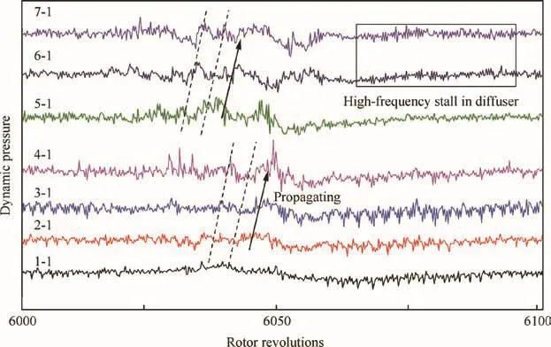
Fig.10 Pressure signals at different radial locations during deep surge under OGV=0°.
In view of the mechanism of stall and surge generation,the pressure fluctuation amplitude at each radial location during the gradual process of entering deep surge is worthy of further investigation.The standard deviation is used as an indicator to reflect the pressure fluctuation amplitude over a period of time.The standard deviation(σ)is calculated based on 10000 data points collected continuously within 0.5 s at different measuring points.The formula of the standard deviation is as follows:
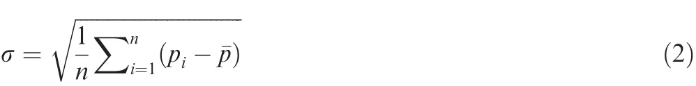
where pirepresents the pressure values at different times and¯p represents the average pressure during this period.
Compared with a baseline at the design condition,the standard deviations at each position under different operating conditions are shown in Fig.11.The eight different operating conditionsgiven in Fig.11 correspond to the conditions marked in Fig.7 respectively,including the operating points I-VI,mild surge,and deep surge.With the signals at different radial positions phase-converted,the standard deviations are all at the same phase in the circumferential direction,so that the radial differences can be discussed.
According to Fig.11,from the pre-stall condition to deep surge,the standard deviation of the pressure signal at the impeller middle-rear region is the largest,which corresponds to the phenomenon that flow instability originates in the impeller instead of the diffuser.If the standard deviation can be used to measure the impact of a component on the overall stability,the flow stability at the impeller middle-rear region may be the worst under OGV=0°.In the numerical simulation result of a similar impeller,19an unstable flow also originates at the impeller middle-rear region.It shows that this indicator can be used to determine the unstable region in the impeller at low flow rates.
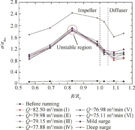
Fig.11 Pressure fluctuation amplitude of each radial location under OGV=0°.
Based on the above analysis and discussion,the mechanism of stall or surge generation under OGV=0°can be deduced.Flow instability at the impeller middle-rear region,such as a tip leakage flow or vortex,may be the core factor affecting the overall stability of the compressor.However,the specific form of this unstable flow still needs to be further confirmed by numerical simulation or visualization experiments.This will be the next step of our research.In summary,an unstable flow originates at the impeller middle-rear region,and a highfrequency stall wave occurs firstly in the impeller during mild surge.Then the flow disturbance propagates downstream,and a high-frequency stall occurs in the diffuser prior to deep surge.The occurrence of the high-frequency stall can be considered as the deep surge inception.
In term of the physical relationship,the violent pressure fluctuations in the diffuser can directly lead to an imbalance for the pressure distribution of the outlet piping system,since the diffuser is closer to the compressor outlet,and this pressure imbalance is exactly the mechanism of surge occurring.Thus,a highfrequency stall occurring in the diffuser can always trigger a deep surge.However,according to the above analysis,this stall pattern originates in the impeller.It is the product of an unstable flow in the impeller,such as a tip leakage flow or vortex.
3.4.Effects of different diffuser vane angles
Since the diffuser type is a variable vaned diffuser,the diffuser vane angle may be an important factor affecting the mechanism of stall and surge generation,which requires further analysis and discussion.The pressure signals at each radial position under two different OGVs are shown in Figs.12 and 13,respectively.In these two cases,the standard deviation of each radial position is shown in Fig.14.
Under OGV=12°,the pressure signals at each radial location during a mild surge at the operating condition point d1in Fig.6 are shown in Fig.12.A mild surge wave with the Helmholtz frequency is firstly captured in the diffuser inlet,accompanied by a high-frequency stall wave.It is hard to identify the phase difference between the pressure signals at different radial locations.Moreover,when the value of the abscissa is about 50 revolutions,there is also a clear surge wave at the impeller inlet,with a similar period and a weaker amplitude.The standard deviations at each radial location are shown in Fig.14(a).The position of the unstable point moves downstream compared with that under OGV=0°.Thus,the mechanism of stall and surge generation is also changed.When the diffuser vane angle is turned positively causing the air flow incidence angle at the diffuser inlet to increase,the aerodynamic load is increased,and the interaction between the impeller and the vaned diffuser becomes the core factor of stall or surge generation.Considering some numerical simulation results on centrifugal compressors in recent years,20,21flow instability at the impeller outlet is also closely associated with the tip leakage and vortex in the impeller,and in this situation,the typical jet-wake structure at the impeller outlet leads to a strong instability under the influence of the diffuser blades,so that the unstable point moves to the vaneless region between the impeller and the diffuser,which is confirmed by the details in Figs.12 and 14(a).Since an unstable flow originates there,both high frequency stall and mild surge occur originally in the diffuser,and then transform into deep surge directly.Unlike the case of OGV=0°,there is not a gradual process that this stall pattern propagates from the impeller to the diffuser during mild surge,and this kind of high-frequency stall occurring in the diffuser can always trigger a deep surge.
Under OGV=-12°,the pressure signals at each radial location during the mild surge at the operating point d5in Fig.6 are shown in Fig.13.A mild surge wave with the Helmholtz frequency occurs originally at the impeller inlet,accompanied by a modal-type stall wave.They can be observed at each radial location of the compressor.The standard deviations at each radial location are shown in Fig.14(b).When the diffuser vane angle is turned negatively causing the air flow incidence angle at the diffuser inlet to decrease,the instability of the impeller leading-edge region is relatively large during mild surge.An unstable flow originates at the impeller inlet and extends to the overall machine,which is confirmed by the details in Fig.13.Interestingly,this phenomenon is consistent with the results of some experiments and numerical simulations in centrifugal compressors with vaneless diffusers.11,22The effect of the diffuser vane on the stability of the impeller is greatly reduced when the air flow incidence angle at the diffuser inlet is small.Except for the region where mild surge and modal-type stall wave originates,the process of deep surge occurring is similar to that under OGV=0°.
According to Figs.12 and 13,when the diffuser vane angle is adjusted,both the form of unstable signals and the location of the original occurrence change,which implies a new mechanism of flow instability.The unstable region obtained by the standard deviation analysis changes,which corresponds well to the dynamic test results.Thus,the standard deviation can be used as an indicator to determine the effects of the stability of individual components on the overall machine stability,which can provide a guidance for methods of improving stability in centrifugal compressors,such as casing treatment.23For example,if a holed casing treatment is used at the unstable point positioned by this method,instability will be well suppressed at unstable conditions.
According to Figs.11 and 14,under three specific diffuser vane angles,the amplitudes of the pressure fluctuations at each radial location during deep surge are all increased by approximately 30%compared with those during mild surge.The stan-dard deviation can also serve as an important quantitative indicator of the distinction between mild surge and deep surge.
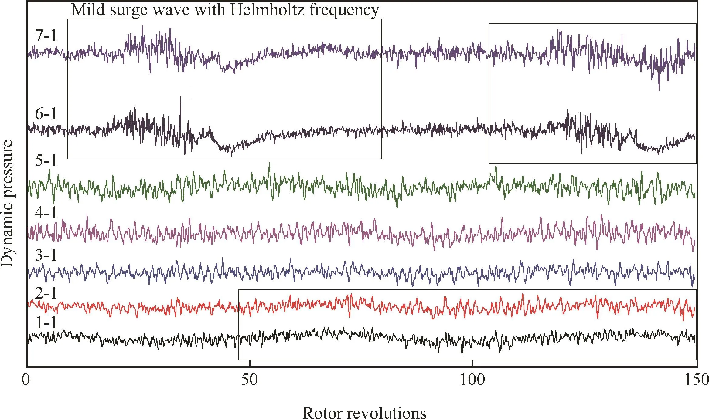
Fig.12 Pressure signals at different radial locations during mild surge under OGV=12°.
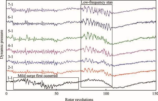
Fig.13 Pressure signals at different radial locations during mild surge under OGV=-12°.

Fig.14 Pressure fluctuation amplitudes of each radial location under OGV=12°and-12°.
4.Conclusions
Experiments have been carried out at different diffuser vane angles to obtain the characteristics of stall and surge in a centrifugal compressor with a variable vaned diffuser.The mechanism of stall and surge is investigated and some conclusions are obtained as follows.
(1)Under OGV=0°,the air flow separation at the leading edge of the split blade in the impeller is the central factor affecting the overall stability of the compressor.An unstable flow originates at the impeller middle-rear region and a high-frequency stall wave occurs firstly in the impeller during mild surge.Then the flow disturbance propagates downstream,and a high-frequency stall occurs in the diffuser prior to a deep surge.The occurrence of this high-frequency stall can be considered as the deep surge inception.In the experiment,a new phenomenon is observed that stall waves propagate downstream along the flow direction,which is contrary to the previous theory that stall waves just propagate circumferentially.
(2)The mechanism of stall and surge in the compressor differs at different diffuser vane angles.When the diffuser vane angle is adjusted positively which means the air flow incidence angle at the diffuser inlet increases,the aerodynamic load is increased,and the instability of the vaneless region between the impeller and the diffuser is significantly improved.The interaction between the impeller and the vaned diffuser becomes a core factor of instability generation,so that a high-frequency stall and mild surge occur originally in the diffuser and then transform into a deep surge directly.This kind of high frequency stall occurring in the diffuser can always trigger a deep surge.When the diffuser vane angle is adjusted negatively which means the air flow incidence angle at the diffuser inlet decreases,the instability of the impeller leading-edge region is relatively large during mild surge,so that a modal-type stall wave and mild surge occur originally at the impeller inlet which motivate a diffuser stall and deep surge consecutively.
(3)Compared with the baseline at the design condition,the standard deviation of the pressure fluctuation at each radial location can be used as an indicator to determine the effects of the stability of individual components on the overall machine stability,which corresponds well to the dynamic test results.It can provide some guidance for stability extension technologies in compressors.For example,it can determine the best place to apply a holed casing treatment so that stall or surge will be well suppressed at different unstable conditions.
Acknowledgement
This research was supported by the National Natural Science Foundation of China(No.51276108).
1.Haynes JM,Hendricks GJ,Epstein AH.Active stabilization of rotating stall in a three-stage axial compressor.J Turbomach 1994;116(2):226–39.
2.Day IJ.Stall inception in axial flow compressors.J Turbomach 1993;115(1):1–9.
3.Spakovszky ZS,Roduner CH.Spike and modal stall inception in an advanced turbocharger centrifugal compressor.J Turbomach 2009;131(3):031012.
4.Greitzer EM.The stability of pumping systems–The 1980 freeman scholar lecture.J Fluid Eng 1981;103(2):193–242.
5.Storming AH.Rotating stall and surge.J Fluid Eng 1980;102(1):14–20.
6.Greitzer EM.Surge and rotating stall in axial flow compressors–Part II:Experimental results and comparison with theory.J Eng Gas Turb Power 1976;98(2):199–211.
7.Fink DA,Cumpsty NA,Greitzer EM.Surge dynamics in a freespool centrifugal compressor system.J Turbomach 1992;114(2):321–32.
8.Greitzer EM.Surge and rotating stall in axial flow compressors–Part I:Theoretical compression system model.J Eng Gas Turb Power 1976;98(2):190–8.
9.Greitzer EM,Moore FK.A theory of post-stall transients in axial compression systems–Part II:Application.J Eng Gas Turb Power 1986;108(2):231–9.
10.Spakovszky ZS.Backward traveling rotating stall waves in centrifugal compressors.J Turbomach 2004;126(1):1–12.
11.Zheng XQ,Liu AX.Phenomenon and mechanism of two-regimesurge in a centrifugal compressor.J Turbomach 2015;137(8):081007.
12.Zheng XQ,Sun Z,Kawakubo T,Tamaki H.Experimental investigation of surge and stall in a turbocharger centrifugal compressorwith a vaned diffuser.Exp Therm Fluid Sci 2017;82:493–506.
13.Tamaki H.Experimental study on the effect of diffuser vane setting angle on centrifugal compressor performance.J Turbomach 2017;139(6):061001.
14.Liu AX,Zheng XQ.Methods of surge point judgment for compressor experiments.Exp Therm Fluid Sci 2013;51:204–13.
15.Munari E,Morini M,Pinelli M,Spina PR,Suman A.Experimental investigation of stall and surge in a multistage compressor.J Eng Gas Turb Power 2017;139(2):022605.
16.Vo HD,Tan CS,Greitzer EM.Criteria for spike initiated rotating stall.J Turbomach 2008;130(1):011023.
17.Yang Z,Zhao J,Wang Z,Xi G.Numerical investigation of diffuser flow field and rotating stall in a centrifugal compressor with vaned diffuser.New York:ASME;2017.Report No.:GT2017-63913.
18.Dehner R,Selamet A,Keller P,Becker M.Simulation of mild surge in a turbocharger compression system.SAE Int J Engines 2010;3:197–212.
19.Zhang TT,Wang T,Wang H,Gu CG.Unsteady and multi-blade passage numerical simulation on an unshrouded centrifugal impeller.New York:ASME;2016.Report No.:GT2016-56873.
20.Schleer M,Abhari RS.Clearance effects on the evolution of the flow in the vaneless diffuser of a centrifugal compressor at part load condition.J Turbomach 2008;130(3):031009.
21.Zhao H,Wang Z,Xi G.Unsteady flow structures in the tip region for a centrifugal compressor impeller before rotating stall.Sci China Technolog Sci 2017;60(6):924–34.
22.Stein A,Niazi S,Sankar LN.Computational analysis of stall and separation control in centrifugal compressors.J Propul Power 2000;16(1):65–71.
23.Liu XH,Sun D,Sun XF,Wang XY.Flow stability model for fan/compressors with annular duct and novel casing treatment.Chinese J Aeronaut 2012;25(2):143–54.
杂志排行

CHINESE JOURNAL OF AERONAUTICS的其它文章
- An efficient aerodynamic shape optimization of blended wing body UAV using multi- fidelity models
- Effect of multiple rings on side force over an ogive-cylinder body at subsonic speed
- Dynamic temperature prediction of electronic equipment under high altitude long endurance conditions
- Experimental investigation on static/dynamic characteristics of a fast-response pressure sensitive paint
- Takagi-Sugeno fuzzy model identification for turbofan aero-engines with guaranteed stability
- Experimental study on film cooling performance of imperfect holes