Design and test of an RF acceleration system loaded with magnetic alloy for the proton synchrotron of the Xi’an Proton Application Facility
2018-06-27GuangRuiLiShuXinZhengHongJinZengZhiYuWangCaiJunYuGangFuHongJuanYaoXiaLingGuanXueWuWangWenHuiHuang
Guang-Rui Li•Shu-Xin Zheng•Hong-Jin Zeng•Zhi-Yu Wang•Cai-Jun Yu•Gang Fu•Hong-Juan Yao•Xia-Ling Guan•Xue-Wu Wang•Wen-Hui Huang
1 Introduction
The Xi’an Proton Application Facility(XiPAF)is a facility dedicated to the experimental simulation of the space radiation environment,especially the investigation of the single event effect(SEE)[1].The facility uses a compact proton synchrotron[2]as its final-stage accelerator.The synchrotron can accelerate a proton beam from 7 to 230MeV changeably,which means the radio frequency(RF)system should work in a wide band of~1-6MHz.Although the synchrotron works in slow cycling mode,we aim to achieve a large acceleration voltage of 800V.With higher acceleration voltage,the synchrotron can provide a larger momentum acceptance.Therefore,we may eliminate the debuncher cavity in the injection line.The maximum beam intensity after injection is~2×10¹¹protons per pulse(ppp).The space charge effect is very significant during the early acceleration stage.Consequently,we plan to introduce the second harmonic wave to reduce the bunching factor,which can suppress the space charge effect.
A compact RF acceleration system loaded with magnetic alloy(MA)is proposed to ful fill the requirements of XiPAF’s synchrotron.Compared with ferrite,the traditional loading material,MA has a much higher saturation flux density,a very low Q value,and much better thermal stability[3].Because of these properties,MA is considered a good option as the load material of the cavity for lowand medium-energy proton synchrotrons.The low-Q-value property allows the system to work in a wide frequency band without active tuning control.This property results in a simple system that is favored in medical ion synchrotrons[4–6].Because of the high saturation flux density and good thermal stability of MA,it can provide a high acceleration gradient,which can significantly shorten the length of the acceleration system.Some rapid cycling synchrotrons[7,8]and fixed- field alternating gradient accelerators[9]have applied high-gradient cavities loaded with MA.Beam acceleration with multiharmonics can reduce beam loss from the space charge effect in high-intensity machines[10,11].The low-Q-value property of MA also makes it possible to apply multiharmonics in the same cavity,thus resulting in a shorter total cavity length[12,13].
Based on the measured data of the MA core,in this study we design and develop a compact RF acceleration system for XiPAF’s proton synchrotron.We present the main considerations and detailed design of the whole system.Test experiments are conducted to verify the performance of the system under high-power condition.The performance limitation of the system is also revealed through experimental data and thermal analysis.
2 System design
2.1 Design targets
XiPAF’s synchrotron works in slow cycling mode,with an injection energy of 7MeV and an extraction energy that varies from 60 to 230 MeV.The ramping time varies from 0.25 to 0.5 s and the maximum ramping speed is 5T/s.The typical RF voltage and frequency patterns of XiPAF’s synchrotron are shown in Fig.1.The voltage is ramped slowly in 10ms to the maximum acceleration voltage to capture the beam adiabatically into the longitudinal bucket.The second harmonic RF only operates during the lowenergy stage to increase the acceptance of the RF bucket and suppress the space charge effect.After reaching the target beam energy,the fundamental RF voltage is reduced to a low value to suppress the momentum spread and reduce power consumption.

Fig.1(Color online)Typical RF voltage and frequency pattern of XiPAF’s synchrotron.V1denotes the voltage of the first harmonic,and V2denotes the voltage of the second harmonic
The design targets of the RF system of XiPAF’s synchrotron are listed in Table 1[14].The initial beam energy spread is a major limitation of the acceleration efficiency of low-energy proton synchrotrons working in the slow cycling mode.One solution is to use a debuncher cavity to reduce the injection beam’s energy spread,but this would make the whole system more complicated to build and operate.In the case of XiPAF,multiparticle simulation demonstrates that,with a relative large RF voltage of~ 800V and good system stability,the RF bucket’s momentum acceptance becomes sufficiently large to directly accelerate the injection beam with high efficiency.Compactness is another important requirement for the system,as the free space on the ring left for the RF cavity is≤1.0m.For easy operation,we plan to use a low-powerconsumption design and forced air to cool the system.
2.2 MA cores
The shunt impedance Rp of the MA core can be expressed as[16]

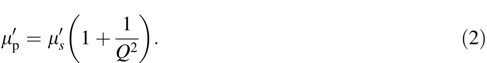
where ro,ri,and t are the outer radius,inner radius,and thickness of the core,respectively.The product()is independent of the core size and is used to evaluate the performance of the magnetic material.Q is the Q value of the material,defined as,andis the complex permeability of the material.Here,is calculated as
As a dispersive material,the MA’s material property has a dependence on RF frequency f.The impedance of the MA core can be expressed as a parallel formZcore=(Rp)//(jωLp),where parallel inductance Lp is calculated as[16]
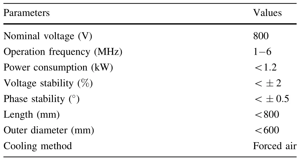
Table 1 Design targets of the RF system

The material of the MA core used in this study is 1K107,produced by AT&M(www.AT&M.com).The thickness of the ribbon is 18 μm and it is insulated by a 2-μm SiO2electric insulator.The filling ratio of the core is~75%.Several small sample cores have been made to measure the material’s()product.Based on the measured result,the ro,ri,and t values of the large-sized core are determined to be 450,300,and 25 mm,respectively,to make the core’s impedance around 50Ω at 1MHz.Two largesized cores(see Fig.2)are fabricated to test their properties under high-power condition.Our test experiment shows that the large-sized core can sustain 2kW instantaneous input power,corresponding to an average power density of 1.4 W/cm3.The core works normally under a 500-W continuous power input without forced cooling[17].With this power level,each core should be able to produce a voltage of>200V;hence,six cores are suf ficient for this project.
Six large-sized MA cores with similar()products and good appearance are selected for the project.The measured()product and Q value of each core are shown in Fig.3.The difference of()between each core is controlled to<±10%in the frequency range of 1-6MHz.The shunt impedances of the cores range from 50 to 120Ω.
2.3 Cavity structure and impedance

Fig.2(Color online)Large-sized MA core made of 1K107
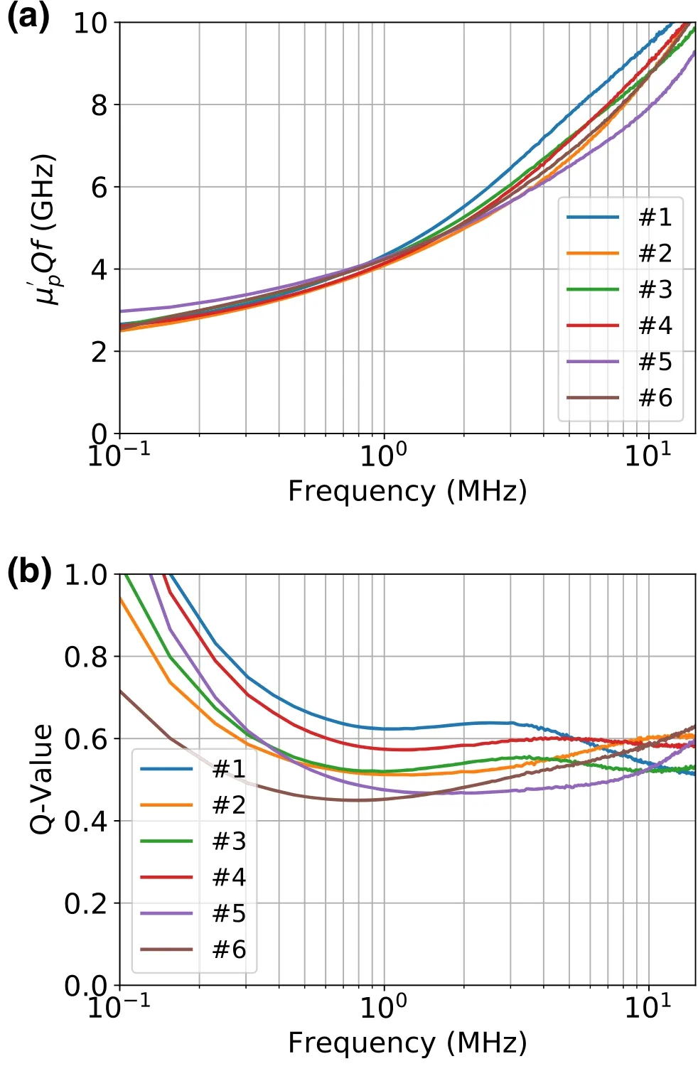
Fig.3(Color online)a(μ′pQf)products and b Q values of largesized MA cores
The cavity has one acceleration gap and each side of the gap has a quarter-wave resonator,each loaded with 3 MA cores.The mechanical structure of the cavity is shown in Fig.4.As can be seen,three axial fans are installed at the downside of the cavity for core cooling.The diameter of the fan is 162mm,and the maximum output wind velocity is 5.5m/s.A detection circuit is installed at the gap to monitor the acceleration voltage for feedback control.The circuit consists of two bridge resistors with impedances of 40 and 4kΩ,respectively,and the divided voltage is then converted to a single-ended signal by a balun circuit and then transferred to a low-level-RF(LLRF)system.
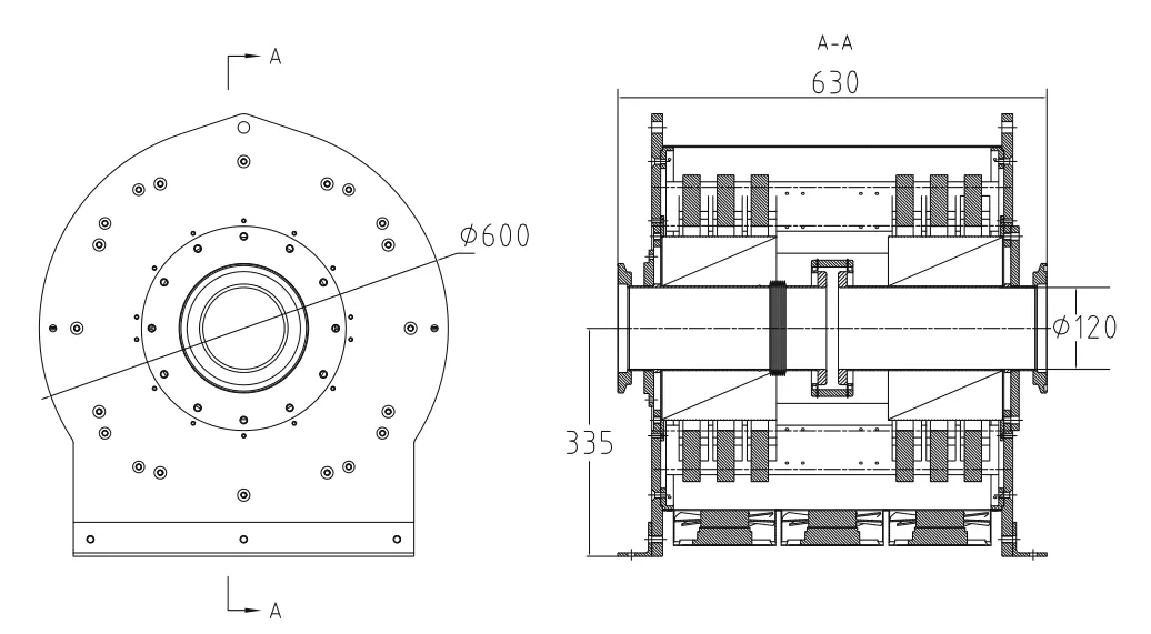
Fig.4 Left view of the cavity(left)and cross section from the front view(right)
The system employs a power feeding method called‘‘Multiple Power Feeding,’’ which means that each amplifier with an output impedance of 50Ω is independently coupled with the MA core.The equivalent circuit of the cavity can be represented as shown in Fig.5[15],where C is the equivalent capacitance of the cavity.Here,C is calculated as

where Cgapis the capacitance of accelerating gap and Ccoax
is the capacitance of coaxial resonator.Here,Cgapand Ccoaxare calculated as
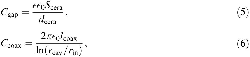
where∈,Scera,and dceraare the relative dielectric permittivity,cross-sectional area,and length of the ceramic gap,respectively,and lcoax,rcav,and rinare the length of the coaxial resonator,the outer radius of the cavity,and the radius of the inner conductor,respectively.The impedance of each loop is obtained as
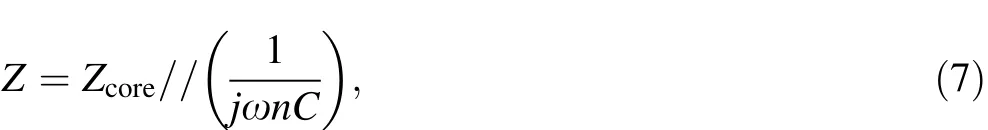
where n is the total number of MA cores in the cavity.The parameters of the cavity are summarized in Table 2.

Fig.5 Equivalent circuit of the cavity using multiple power feeding technology,where n represents the number of cores in the cavity
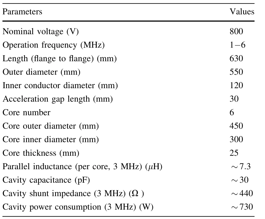
Table 2 Parameters of the cavity
Fig.6(Color online)Impedance and standing wave ratio(SWR)of one loop as a function of RF frequency.Shown are the measured and calculated results of a impedance and b SWR
The impedance seen by each amplifier is measured by a vector network analyzer.The measured results are compared with the calculated values as shown in Fig.6(where only one loop is shown as an example).The measured result is roughly consistent with the calculated result,which indicates that the real capacitance of the cavity is a little smaller than our estimation.The standing wave ratio is<2.0 in the working band;hence,the power reflection percentage should be<9%.
2.4 RF power source
The block diagram of the whole system is shown in Fig.7.Six wideband solid-state amplifiers are used as the RF power source.As described in Sect.2.2,the MA core’s impedance is designed to be~50Ω,so that we can control the reflection power to an acceptable level without special impedance matching.The maximum output power of each amplifier is~300W.The gain of the amplifier decreases from 31.5 to 29.5dB in the frequency range of 1-6MHz.The deviation of gain between each amplifier is<±0.8dB.As the gain of each amplifier is only~30dB,to reach its maximum power level,we added a 20-dB small amplifier to pre-amplify the LLRF signal of the direct digital synthesizer(DDS).The largest distortion of the sine wave comes from the third-order harmonics,whose level is~-23dBc in the work frequency band.
2.5 LLRF control system
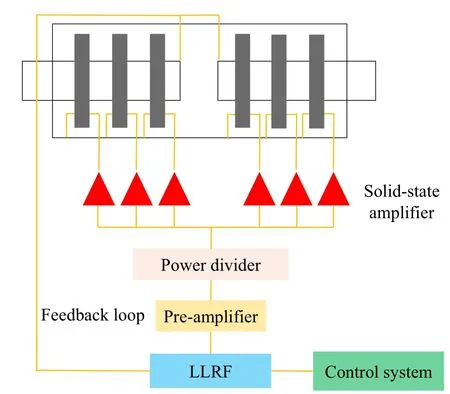
Fig.7(Color online)Block diagram of the RF system

Fig.8(Color online)Block diagram of the LLRF control system
Figure 8 shows the block diagram of the LLRF control system.As can be seen,the programmed data of amplitude,frequency,and phase of the RF signal are transferred from the central control system via Ethernet to the local memory of the LLRF control system before the operation of the synchrotron.The programmed data are then processed by a feedback control algorithm and then amplified and transmitted to the RF cavity.The amplitude of the output RF signal obtains feedback according to the measured voltage of the RF cavity.A beam position monitor(BPM)is used to detect the radial beam orbit displacement ΔR,and the system uses this signal for frequency feedback compensation.An fast current transformer(FCT)is used to detect the synchrotron phase of the bunched beam.The system then compares the synchrotron phase to the setting phase of the beam,Δφ,and makes an RF phase compensation.The maximum delay of the Δφ feedback is <10μs,which is much smaller than the period of synchrotron oscillation(~1ms).
We use one field-programmable gate array(FPGA)and two DSPs for high-speed digital signal processing.The proportional-integral-derivative(PID)control algorithm and feedback control algorithm are implemented in the FPGA.The digital signal processor(DSP)is used to assist in data processing,downloading,and uploading.Two 16-MB synchronous dynamic random-access memory chips are installed on the board to serve as the local memory of the LLRF control system.
3 High-power-experiment results
High-power experiments were conducted to examine the performance of the proposed system.An acceleration voltage of 800V is achieved in the frequency range of 1-6MHz.We have also built a wave of dual harmonics in the same cavity to verify the wideband property of the cavity.The sample voltage waveforms of both single and dual harmonics are shown in Fig.9.

Fig.9(Color online)Voltage waveforms measured at the gap of the cavity.a Single harmonic with a peak–peak voltage of ~1.6kV at 3MHz.b Dual harmonics with a peak–peak voltage of ~1.6kV.The frequency of the first harmonic is 2.0MHz,and the frequency of the second harmonic is 4.0MHz.The amplitude of the second harmonic is~50%of that of the first harmonic to form a flat region at the center of the waveform.The yellow and green lines are the voltages of the left and right sides of the gap to the ground,respectively.The purple line is the acceleration voltage,which represents the difference between the yellow signal and green signal
Owing to the wideband property of the cavity,the waveform of the gap voltage suffers from the higher-order harmonic of the power source,as shown in Fig.9.The spectrum analysis of the gap voltage waveform shows that the main distortion also comes from the third-order harmonic and its level is<-20dBc.
The input and reflection power of each loop to build an 800 V gap voltage are measured.Because of the spread of the gain factor between each amplifier,the input power of each loop has a spread of~±40W.The total input power Pinand reflection power Preare shown in Fig.10.The input power is consistent with the calculated result.The theoretical reflection power of each loop is≤10W,which is too small to be measured accurately.Thus,the measured total reflection power is not well consistent with the calculation result.
For the MA core used in this project,the maximum magnetic flux density in the core with an input power of 1kW/core is only 33mT(at 1MHz),which is much less than the saturation flux density of the material.Thus,the maximum voltage that the cavity can reach depends on the performance of the cooling system.The balance temperature rise of the core surface can be estimated by using the equation

Fig.10(Color online)The total input and reflection power as a function of frequency.The gap voltage is fixed at 800 V

where α is the convection coefficient between the core and cooling air,and g(r)is the volume energy density at a core radius r.In addition,g(r)is inversely proportional to r and can be expressed as

where P is the RF power consumed by the core.The maximum temperature rise should occur near the inner core radius ri.The convection coefficient α of air-cooling is difficult to estimate.Therefore,we examine the maximum surface temperature of the core with a thermal camera under a constant gap voltage.The experimental results are shown in Fig.11.With the experimental results of balance temperature,we can estimate that α is ~17W/(m2K)without forced cooling and 55W/(m2K)with forced cooling.Assume that a temperature rise of 60°C is sustainable,the cavity can work normally with an average input power of 2.4kW,which can build a voltage of>1.2kV.In fact,because of the high Curie temperature of MA,this temperature rise limit is very conservative.It should be noted that,in this estimation,it is assumed that heat only conducts along the thickness direction of the core and that the core is only cooled by air convection.Consequently,these values can serve as a rough reference for other systems using a similar cooling method.
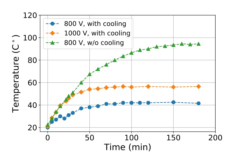
Fig.11 Maximum temperature rise as a function of time with a constant gap voltage
An off-line control experiment was conducted to verify the performance of the LLRF control system.The work pattern was successfully built on the cavity as shown in Fig.12.The voltage envelope is consistent with the setting because the frequency dependence of the system is well compensated by the voltage amplitude feedback loop.The stability of the system is measured as shown in Fig.13.The amplitude ripple level is notably dependent on the amplitude.The amplitude ripple can be controlled to±1.0%if the voltage is>650V.The phase ripple is well below ±0.4°for all amplitude cases.
4 Summary
A compact RF acceleration system loaded with MA cores is developed for XiPAF’s proton synchrotron.The cold and high-power test experiments show that the performance of the system is well consistent with our design.High-power experiments show that the MA core made of 1K107,which has not been widely used in this area before,could be a good option for similar systems.The acceleration voltage can reach 800V in the frequency range of 1-6MHz with an input power of~0.8kW.Furthermore,the thermal analysis shows that,with a further RF power upgrade,the system can work normally with a voltage of>1.2kV.Owing to the wideband property of the cavity loaded with the MA core,the waveform of the gap voltage is easily distorted by the low-order harmonic component of the power source.Therefore,the harmonic level of the amplifier should be carefully controlled.Further online experiments will be conducted to improve and verify the beam–cavity feedback loop.Finally,although the system is dedicated to XiPAF’s proton synchrotron,its performance should satisfy the requirement of medical proton synchrotrons in slow cycling mode with minor system changes.

Fig.12 The envelope of gap voltage measured by the cavity’s detector.The pattern used in the measurement is similar to that shown in Fig.1

Fig.13(Color online)Ripples of the voltage’s amplitude and phase with different voltage levels.a Voltage ripple.b Phase ripple
AcknowledgementsThe authors are grateful to Prof.Hong Sun,Dr.Xiao Li,and Dr.Hua Shi of IHEP for their enthusiastic help on this project.The authors also appreciate Prof.Zhe Xu for his helpful discussions on the system design.Special thanks should be expressed to Xing Hong of AT&M.Without his professionalism and hard work on the fabrication of MA cores,the project could not have progressed so smoothly.
1.S.X.Zheng,Q.Z.Xing,X.L.Guan et al.,Design of the 230 MeV proton accelerator for Xi’an proton application facility,in proceedings of HB,p.55(2016)
2.G.R.Li,X.L.Guan,X.W.Wang et al.,Design of the key parameters in an advanced radiation proton synchrotron.Morden Appl.Phys.6(2),85–89(2015).https://doi.org/10.3969/j.issn.2095-6223.2015.02.004
3.C.Ohmori,E.Ezura,M.Fujieda et al.,High field-gradient cavities loaded with magnetic alloys for synchrotrons,in proceedings of PAC,p.413(1999)
4.M.Crescenti,A.Susini,G.Primadei et al.,The VITROVACR1cavity for the TERA/PIMMS medical synchrotron,in proceedings of EPAC,p.1591(2000)
5.K.Saito,H.Nishiuchi,H.Sakurabata et al.,Multi-harmonic RF acceleration system for a medical proton synchrotron,in Proceedings of EPAC,p.1045(2004)
6.M.Kanazawa,T.Misu,A.Sugiura et al.,RF cavity with co-based amorphous core.Nucl.Instrum.Meth.A 566,195–204(2006).https://doi.org/10.1016/j.nima.2006.05.276
7.C.Ohmori,S.Anami,E,Ezura et al.,High field gradient cavity for J-PARC 3 GeV RCS,in proceedings of EPAC,p.123(2004)
8.P.Huelsmann,H.Klingbeil,U.Laier et al.,Development of a new broadband accelerating system for the SIS18 upgrade at GSI,in proceedings of IPAC,p.744(2010)
9.A.Takagi,Y.Mori,J.Nakano et al.,Radio frequency acceleration system for 150 MeV FFAG,in proceedings of PAC,p.1231(2003)
10.A.Seville,I.Gardner,J.Thomason et al.,Progress on dual harmonic acceleration synchrotron,in proceedings of EPAC,p.349(2008)
11.J.F.Chen,J.Y.Tang,Studies of dual-harmonic acceleration at CSNS-II,CPC(HEP&NP),34(10),1643–1648(2010).https://doi.org/10.1088/1674-1137/34/10/018
12.C.Ohmori,M.Kanazawa,K.Noda et al.,A multi-harmonic RF system using a MA cavity.Nucl.Instrum.Meth.A 547,249–258(2005).https://doi.org/10.1016/j.nima.2005.03.163
13.F.Tamura,M.Yamamoto,M.Yoshii et al.,Longitudinal painting with large amplitude second harmonic rf voltages in the rapid cycling synchrotron of the Japan Proton Accelerator Research Complex.Phys.Rev.ST Accel.Beams 12,041001(2009).https://doi.org/10.1103/PhysRevSTAB.12.041001
14.XiPAF design group,Design report of XiPAF,Internal report(2014,unpublished)
15.K.Saito,J.I.Hirota,M.Katane et al.,An untuned RF cavity using multifeed coupling.Nucl.Instrum.Meth.A 401,133–143(1997).https://doi.org/10.1016/S0168-9002(97)01026-7
16.H.Klingbeil,Ferrite cavities,(2012),arXiv:1201.1154v1[physics.acc-ph]
17.G.R.Li,S.X.Zheng,H.J.Zeng et al.,Cold and high power test of large size magnetic alloy core for XiPAF’s synchrotron,in proceedings of HB,p.59(2016)
杂志排行

Nuclear Science and Techniques的其它文章
- Gamma irradiation-induced effects on the properties of TiO2 on fluorine-doped tin oxide prepared by atomic layer deposition
- Preliminary analysis of tritium fuel cycle in Z-pinch-driven fusion– fission hybrid reactor
- Investigation of high-temperature-resistant rhenium–boron neutron shields by experimental studies and Monte Carlo simulations
- Monte Carlo simulation of incident electrons passing through thin metal layer
- Annual effective dose values from137Cs activity concentrations in soils of Manisa,Turkey
- Investigation of SPECT/CT cardiac imaging using Geant4