Progress and Challenges in Large Eddy Simulation of Gas Turbine Flows
2018-06-22
(Department of Mechanical Engineering and the Built Environment,College of Engineering and Technology,University of Derby,UK)
cchord
DJfuel injector central jet diameter
DSfuel injector outer diameter
hannulus height
rco-ordinate in radial direction
Uvelocity in axial direction
u’ velocity fluctuation in axial direction
u-rmsroot mean square of velocity fluctuation in axial direction
Vvelocity in radial direction
v-rmsroot mean square of velocity fluctuation in radial direction
w-rmsroot mean square of velocity fluctuation in tangential direction
xco-ordinate in axial direction
φscalar concentration
σφscalar concentration fluctuation
1 Introduction
Enormous progress has been made in Computational Fluid Dynamics(CFD)over the past 30 years with the advancement of computer hardware and CFD software.Now,many open source and commercial CFD software are available,making it possible to carry out complex engineering flow simulations on PCs.Applications of CFD can be found in almost all engineering disciplines such as Aeronautical,Automotive,Mechanical,Chemical etc.,ranging from externalflows,internalflows,multiphase and reacting flows,to multidisciplinary fields like aero-elasticity and aero-acoustics.Apart from a powerful research tool CFD has also become widely accepted as one of the essential analysis tools for design engineers,and plays an important role in the aerodynamic design of gas turbines.
A wide range of CFD modelling and numerical methods have been developed and generally speaking there are three mainstream CFD approaches for computing/simulating turbulent flows:RANS,LES and DNS.The RANS approach which has been used in gas turbines for the past several decades,solving the time-or ensemble-averaged governing equations with all the scales of instantaneous turbulent motion being modelled,is the most efficient approach computationally but lacks accuracy and performs poorly in certain areas.The unsteady RANS(URANS)approach is one step forward in terms of capturing certain unsteady flow phenomena but the improvement is still very limited.On the other hand,all details of turbulent motions are simulated directly with a very fine mesh and a very small time step to resolve flow structures down to the Kolmogorov scales in the DNS approach.However,the computational cost of DNS is prohibitive and hence it has very limited applications in gas turbine flows,mostly restricted to lowpressure turbine flows where the Reynolds numbers are low and the flow is complex involving separation and transition.In LES only large scale motions(called large eddies)are simulated directly while the small scale motions are modelled using a so called Sub-grid scale(SGS)model,leading to a considerable reduction in computational cost compared with DNS.In contrast with the RANS approach LES is more accurate as large eddies(large scale motions),which contain most of the turbulent kinetic energy and are responsible for most of the momentum/heat transfer,are captured directly in LES while they are modelled by a turbulence model in the RANS approach.
Gas turbine flows are inherently unsteady and very complex,which are not only fully turbulent but also could be transitional in certain regions,and involve two phases,heat transfer and combustion as well.A few examples of those complex flows in gas turbines are given below.
·In the turbomachinery main gas path one typical unsteady flow feature is due to the interaction of multiple rows of adjacent stationary and rotating blade pairs(stages).The wakes generated from upstream blades interact with downstream blades,leading to very complex unsteady flows.
·Very complex unsteady flows can also be found in cavities formed between co-rotating disks,or rotating and adjacent static disks in the internal air systems of gas turbines.The flow in those cavities involves very complicated three dimensionalstructures with the presence of cyclonic and anti-cyclonic vortices rotating at about half of the disk rotating speed.The flow can also oscillate between quite different flow regimes with the possibility of vortex breakdown.
·Separation and transition often occurs on the suction surface of Low-Pressure Turbines(LPT)and the unsteady wakes from upstream blades have a big impact on the transition process,which in turn strongly influences the separation and reattachment,leading to a very complex cyclic unsteady process.
·Jet impingements,swirling and recirculating flows,combustion,two phase and cooling flows etc.occur in a gas turbine combustor,resulting in very complex unsteady flows.
Itis very unlikely thatthe RANS/URANS approach can predict accurately the above mentioned complex unsteady flows,and in some cases the RANS/URANS approach may fail completely to capture the essentialflow featuresinvolved in those complex flows.
A brief review on the application of LES in turbomachinery flows will be presented first in this paper,followed by more detailed discussion on LES of two gas turbine combustor related flow cases.A brief discussion and summary of the current status of LES applications in gas turbines and the challenges that we are facing will be given before the conclusion section.
2 LES of Turbomachinery Flows
In this section,a brief review on LES of turbomachinery flowswillbepresented.Thereare several variants of LES such as ILES(Implicit LES),NLES(Numerical LES),MILES(Monotone Integrated LES),VLES(Very Large Eddy Simulation,also regarded asahybridapproach)andthehybridLES/RANS approach will not be discussed in this paper.A review on computation of unsteady turbomachinery flows using different modelling fidelity levels has been given by Tucker[1-2].
2.1 LES of Compressors
It is a big challenge for the RANS/URANS approach to predict gas turbine compressor flows accurately due to a strong influence of the centrifugal force and streamline curvature on turbulence,and especially it is difficult for RANS/URANS to provide accurate predictions at offdesign conditions.In addition,substantial secondary flow may be present,which is also very hard to be captured accurately by RANS/URANS approach.Hence LES is desirable and should provide an accurate representation of the flow physics involved.
You et al.[3-5]carried out LES of rotor tip-clearance flows with a combined curvilinear mesh and immersed boundary conditions using the Smagorinsky SGS model in a Lagrangian dynamic form(averaging the model constant along pathlines).The LES result agree well with measurements and they investigated further the effect of varying tip-gap size on the tip-leakage flow and the viscous loss mechanismin tip-clearance flow [5],demonstrating that viscous losses in the cascade endwall region are mainly due to velocity gradients.Their analysis suggests that the endwall viscous losses can be alleviated by changing the direction of the tip-leakage flow,resulting in the reduction of the associated spanwise derivativesofthe mean streamwise and pitchwise velocity components.
Lee,Kim and Runchal[6]performed LES of flow past a compressor blade cascade,studied the aerodynamic losses and the noise generation by unsteady flows at offdesign conditions,with the far field sound predicted using the Ffowcs Williams-Hawkings approach.Their results show that the separated vortices in each passage do not occur simultaneously and at large incidence angles the typical mode of rotating instability is present.At small incidence angles,typical turbulent boundary layer noise with a few narrow humps suggests more like dipole sound due to its surface curvature,otherwise it is quadrupole in nature.
LES was employed by Hah[7]and Hah et al.[8]to investigate unsteady flow behaviourin a transonic compressor rotor(NASA rotor 37),and their LES results agree well with the measured compressor characteristic.More accurate prediction of total pressure loss in the hub region was obtained using LES compared against typical RANS predictions.Furthermore LES also shows superiority over RANS in capturing some complex flow features such as the intermittent dynamics of the shock,tip vortex and wake interaction.
The capability of LES to simulate transitional separated flow over a compressor blade at two free stream turbulence levels(0 and 3.25%)was assessed against DNS by Lardeau,Leschziner and Zaki[9].The main conclusion is that LES,with a small fraction of the computationalresources required for a fullDNS resolution,provides credible representation of transition provoked by a combination of free stream turbulence as shown in Figure 1,and the LES results of streamwise variation of free-stream-turbulence intensity agree well with the DNS results as shown in Figure 2.However,at zero free stream turbulence,LES results are sensitive to the SGS models used and the main discrepancies between LES and DNS results occur in the early stage of transition in the separation bubble.At the high level of free stream turbulence the sensitivity to SGS models is much lower with better agreement between LES and DNS results.
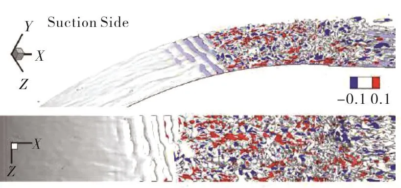
Fig.1 Perspective and top views of the Q-criterion colored by streamwise velocity fluctuations(-0.1<u'/U<0.1)[9].
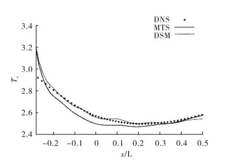
Fig.2 Comparison between the LES and DNS results of free-stream-turbulence intensity:solid line-LES results obtained using a mixed-time-scale(MTS)model;dotted line-LES results obtained using a dynamic Smagorinsky model(DSM);symbols-DNS results[9].
McMullan and Page[10]carried out a series of LES of flows relevant to axial compressors,ranging from an idealized linear cascade to a research 3.5 stage compressor rig,to assess the applicability of the LES technique as a tool for axial gas turbine axial compressor design.There is an overall good agreement between the LES results and experimental data.Their study demonstrated the superiority of LES over RANS in terms of capturing separation-induced transition in the flow and elucidating new physical processes through the discovery of toroidal vortices in the stagnation region of the flow as shown in Figure 3,leading to the formation of contrarotating vortex pairs around the leading edge.They also pointed out the computational complexity of performing LES of real gas turbine axial compressors,especially that an accurate specification of the unsteady inflow is crucial.
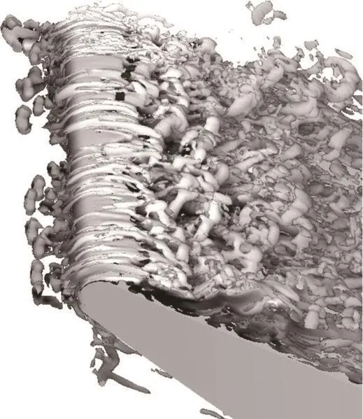
Fig.3 Iso-surface of Q>0 showing toroidal structures upstream of the leading edge of the blade,which periodically shed from the stagnation region and are stretched over the leading edge of the blade,resulting in pairs of contra-rotating vortices[10].
Hah,Hathaway and Katz[11]carried out LES of unsteady flows in a low speed one and half stage axial compressor at near stall operation.They studied the effect of rotor tip gap size on flow structures.At a smaller rotor tip gap,the tip clearance vortex was observed to move toward the leading edge plane,generating an almost circumferentially aligned vortex around the entire rotor while the clearance vortex remains inside the blade passage at a large tip gap.
Gourdain[12]carried outURANS and LES of turbulent unsteady flows in a stage of an axial subsonic compressor and presented a comparison of the URANS and LES results against experimental data.It was shown that LES produced better predictions of time-dependent quantities.However,neither URANS nor LES predicted accurately the compressor performance(efficiency and pressure ratio).
LES was performed by Gao et al.[13]to investigate turbulent flow characteristics of corner separation in a compressor cascade(NACA65 blade profiles).A good agreement was obtained between the LES results and experimental data in terms of mean aerodynamics of the corner separation,especially for the blade surface static pressure coefficient and the total pressure losses.
LES of three-dimensional flow separation in an axial compressor was performed by Scillitoe,Tucker and Adami[14]to investigate the loss sources under the influence offree stream turbulence and end wall boundary layer state.Their results show that the core loss sources are the 2D laminar separation bubble and trailing edge wake,and also the 3D flow region near the end wall.They further demonstrated thatfree stream turbulence has relatively less impact on loss whereas the end wall boundary layer state has a significant influence on loss.This is because a laminar end wall boundary layer separates much earlier leading to a larger passage vortex,resulting in significant alternation of the end wall flow and loss.
2.2 LES of Turbines
In modern aero engines the number of low-pressure turbine(LPT)blades is reduced to lower the weight and cost of the engine.Hence,LPT blades are highly loaded,leading to extreme flow turning.As a result of the increased flow turning and severe adverse pressure gradients on such LPT blades,plus the fact that the LPT blade Reynolds numbers are low,flow separation and transition occurs and also stronger secondary flows exist at the end walls.It is highly unlikely that the RANS/URANS approach can provide accurate predictions and high fidelity numerical simulations are need to capture the complex flow physics involved.
Mittal,Venkatasubramanian and Najjar[15]performed LES of the flow through a LPT cascade to assess the capability of LES in predicting flow separation and the losses associated with the separation.They simulated flows at two Reynolds numbers of 10 000 and 25 000.At Reynolds number of 10 000 their results suggest that the dynamics of the separation phenomenon on the suction surface is governed by the Karman vortex shedding type behavior in the wake.However,they also argued that when Reynolds number increases,the separating shear layer on the suction surface is likely to be governed more by a Kelvin-Helmholtz type shear layer instability.
Michelassi, Wissink and Rodi[16]carried out numerical studies of periodic unsteady flow in a LPT cascade using DNS,LES and URANS.Overall the LES results agree well with the DNS results although adelayed transition by about10% ofchordwas predicted by LES in comparison with the DNS prediction.A fair reproduction of the periodic unsteady flow in theLP turbinepassagewasprovided by URANS but some detailed flow patterns revealed by both DNS and LES are lost.In addition,DNS and LES produced useful information for improving the results of URANS.
Flow separation and transition around a LPT blade was studied by Raverdy,Mary and Sagaut[17]using LES.TheLES resultsofmean and turbulentquantities compare well with experimental data and the interaction between the transition process and the wake from upstream blade is analyzed.Their study shows that the primary two-dimensional instability that originates from the free shear in the bubble is the Kelvin-Helmholtz mechanism.
Sarkar and Voke[18]carried out a numerical study of interaction of passing wakes and inflexional boundary layer over a LPT blade using LES and observed coherent flow structures due to the complex interaction of passing wakes and the separated shear layer.Further study of the effect of wake structures on unsteady flow over the suction side of a LPT blade was conducted by Sarkar[19]using LES.It was shown that the wake length scale has a big impact on the large pressure oscillations and roll-up of the separated shear layer at the rear half of the suction surface. Furthermore, the characteristics of wake turbulence have a significant influence on the transition of the roll-up shear layer.
Matsuura and Kato[20]conducted LES of compressible transitional cascade flows to investigate the effects of free-stream turbulence.Their LES predictions agree closely with experimental data and demonstrate that the intensity levelsoffree-stream turbulence have a significant influence on the generation of pressure waves near the trailing edge.
Jimbo et al.[21]carried out LES of unsteady viscous flow around a high pressure turbine cascade to understand the pressure loss mechanism.Their LES results agree well experimental data.Further analysis of the LES results show that a large unsteady vortex is formed in a region downstream of the trailing due to the interaction of the vortex generated on the suction and pressure surface of the blade and the secondary vortex generated on the end-wall.They argued that this unsteady three-dimensionalflow characteristic may play an important role in the pressure loss mechanism.
Flow in a LPT cascade was simulated using LES by Medic and Sharma[22].LES results over a range of Reynolds numbers for three LPT aerofoils have been compared against measurements,showing that LES is capable of capturing the main trends across all three geometries.
Papadogiannis et al.[23]performed LES of a high pressure turbine stage to study the effects of SGS modelling and mesh resolution.The employed a wallmodeled LES approach,where wall flow physics is modeled by a law-of-the-wall rather than directly captured by a fine mesh.In comparison with experiment data,the LES results show improvement over URANS predictions.Nevertheless,it was shown that with a coarse mesh SGS models had a strong influence on the results,leading to different flow fields characterized by different shock structures and unsteady contents.
Cui,Rao and Tucker[24]studied flow physics on the suction surface,pressure surface,and end walls of a LPT blade under the influence of different inflow boundary conditions by means of LES.They found decreased pressure fluctuations on the aft portion of the suction side at high free stream turbulence.This is due to a different transition mechanism at high free stream turbulence.On the pressure side,elongated vortices were observed at low free stream turbulence but disappeared at high free stream turbulence level as shown in Figure 4.It was demonstrated that the state of the incoming boundary layer(laminar or turbulent)has a significant influence on the on flow features at end walls.
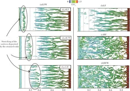
Fig.4 Iso-surface of Q colored by velocity magnitude showing the elongated vortices:a)-low free stream turbulence with wake(LFW);b)-low free stream turbulence(LF);c)-high free stream turbulence(HF);d)-high free stream turbulence with wake[24].
2.3 LES of Internal Air Systems
As mentioned in the introduction section that very complex,three-dimensionalunsteadyflowsexistincavities formed between co-rotating disks,or rotating and adjacent static disks in the internal air systems of gas turbines,which are not amenable to the RANS/URANS approach and high fidelity simulation such as LES is needed for predicting this kind of flows accurately.
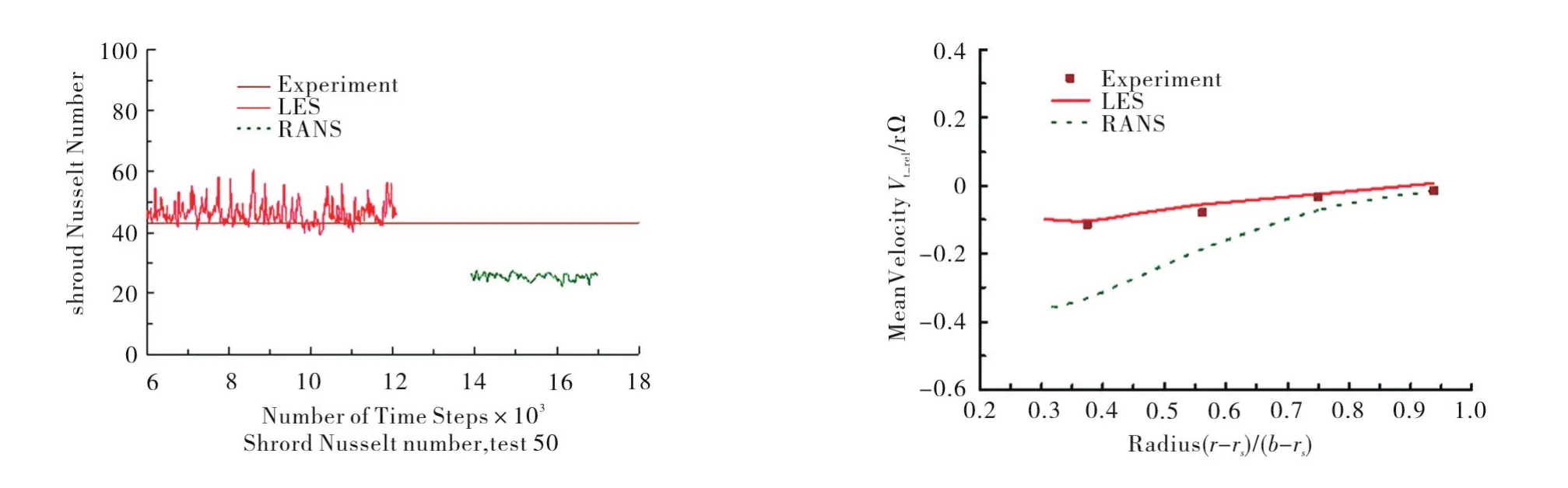
Fig.5 Comparison of flow and heat transfer between LES,RANS,and measurement[25].
Sun et al.[25]carried out a numerical study of buoyancy-affected flow in rotating disk cavities using both LES and URANS.They compared the numerical predictions with experimental data for a range of Grashof number from 1.87 to 7.41×10⁸and buoyancy number from 1.65 to 11.5.LES results are in much better agreement with the measured velocity and heat transfer than URANS results as shown in Figure 5.
Flow between a rotating and a fixed disk,representative of the flow in cavities of the internal air system,was simulated using LES by Andersson and Lygren[26].Five cases with different gap sizes between the disks were considered and it was found that the gap size did not really affect he three-dimensional flow fields near the two disks as the same general features in all cases were observed.
Tuliszka-Sznitko et al.[27]performed LES of the nonisothermal transitional and turbulent flow in rotor/stator sealed cavity with a rotating inner and a stationary outer cylinder and their main goal was to analyze the properties of turbulence of the non-isothermal flow dominated by Coriolis and centrifugal forces.Their results show an increase of turbulent intensity in the stator boundary layer towards the outer cylinder and in the rotor boundary layer 3D spiral vortices are observable.They also observed a rapid enhancement in the heat transfer in the outer endwall area where the turbulent intensity was the largest.
Viazzo et al.[28]studied a turbulent rotor-stator flow numerically using LES with a higher-order finitedifference scheme.Their LES results,both mean and Reynolds stresses,agree well with experimental data.It is also demonstrated that LES is capable of capturing accurately the unsteady flow structures as their simulations predicted the main features of the flow with a fully turbulent stator boundary layer and a transitional rotor layer.Furthermore,coherent flow structures under the form of spiral arms or circles within the rotor and the stator layer respectively are well captured.
Flow in a rotating cavity with narrow inter-disc spacing and a radial inflow was simulated by Onori et al.[29]using various approaches including LES.Very different flow features,such as a turbulent flow region,a laminar oscillating core with almost zero axial and radial velocity and turbulent Ekman type boundary layers along the discs,were captured by LES.
It is very difficult to predict accurately complex unsteady flows occurring in turbine rim seals due to the interaction of the mainstream flow with the internal air system cooling flow.O’Mahoney et al.[30]carried out LES of a turbine stage including a rim seal and rim cavity at a rotational Reynolds numberReθ=2.2 × 10⁶and a main annulus axial Reynolds number of 1.3×10⁶,with different levels of cooling air flow.Their LES results show better agreement with experimental data than URANS results in terms of sealing effectiveness as shown in Figure 6.
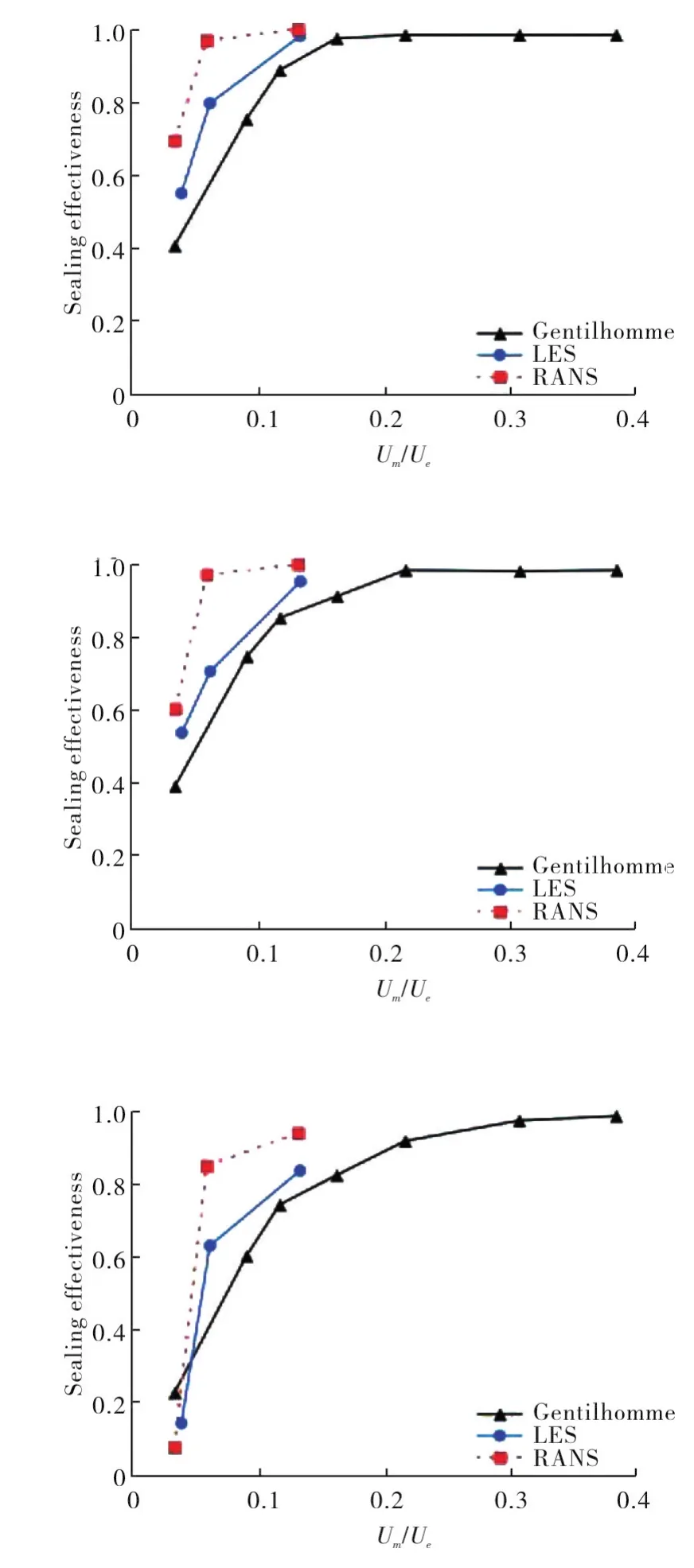
Fig.6 Comparison of sealing effectiveness between LES,RANS,and measurements at different radial locations[30].
Gao et al.[31]conducted numerical studies of turbine rim sealing flows using different CFD approaches.The numericalresultsobtained from LES,RANS and URANS are very similar,allshowing reasonable agreement with steady measurements within the disc cavity.However,only LES is capable of capturing unsteadiness at a similar distinct peak frequency to that found experimentally.
3 LES of Combustor Related Flows
Mesh resolution is a key factor in LES for accurate predictions since most SGS models,generally speaking,are not robust and for high Reynolds number flows the requirement of very fine mesh in near wall regions often becomes a bottleneck for LES applications.This is one major reason why there has not been any application of LES for a whole compressor or a whole turbine since unfeasibly large mesh is required even for a single stage.For combustor flows there is no need to use very fine mesh in the near wall region as boundary layer is not a dominator factor. However, there are additional challenges such as liquid fuel injection,liquid fuel atomization and evaporation,large-scale turbulent fuel air mixing,small scale molecular fuel air mixing,chemical reactions and so on.Despite those additional complexity of the flow,LES has been applied successfully to simulate the flow in real combustion systems.In this section LES of two gas turbine combustor related flows will be discussed and more comprehensive reviews on LES in this area can be found elsewhere[32-33].
3.1 LES of a fuel injector
Dianat et al.[34]and Midgley et al.[35]conducted LES and experimental iso-thermal studies to investigate the mixing processes between the air and fuel streams in the near field of a swirling flow fuel injector.The fuel injector geometry is shown in Figure 7.An annular swirl stream(outer diameterDS=37.63mm)is produced from the radially fed swirler,representing the inflowing air stream(scalar value being 0)in a non-premixed flame fuel injector arrangement.A central jet(diameterDJ=5.4mm)represents the fuel stream(scalar value being 1).Particle Image Velocimetry(PIV)was employed for velocity field measurements and Planar Laser Induced Fluorescence (PLIF)forquantitative scalarmixing measurements.
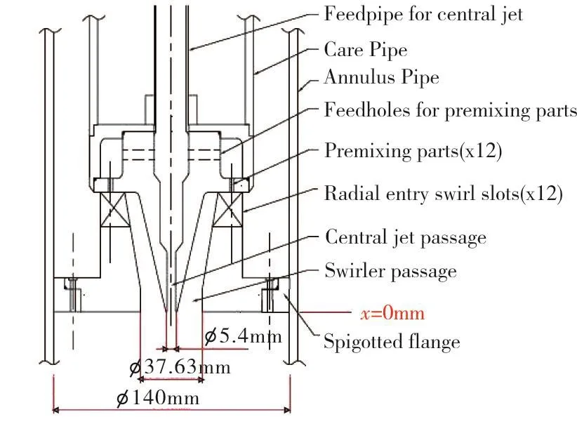
Fig.7 Fuel injector geometry[35].
A 2D view(x-rplane)of the computational domain/mesh is shown in Figure 8.A multi-block grid was generated with a total mesh points of about one million and the mesh was refined in the near wall and free shear layer regions.A finite volume LES code with a structured multi-block,curvilinear staggered grid was used for the simulation and details about the numerical method can be found elsewhere[36].
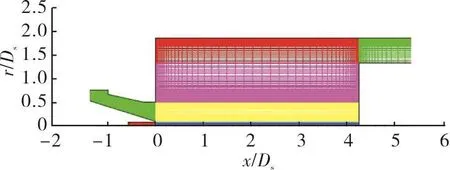
Fig.8 2D view(x-r plane)of computational domain and mesh[34].
Figure 9 shows comparisons of the predicted mean axial velocity and rms profiles against the experimental data at several axial locations near the fuel injector outlet where turbulence activity is highest and scalar mixing is most rapid.It can be seen from Figure 9 that the predicted mean velocity profiles agree very wellwith the experimental data.There are some discrepancies between the predicted rms profiles and the experimental data but the general trends,especially the three peaks of the profile in the closest location to the fuel injector outlet which then develop into two peaks downstream,are well captured by LES.
Figure 10 presents comparisons of the predicted mean and fluctuating scalar concentration against the experimental data at the same axial locations near the fuel injector outlet.As shown in the figure that a good agreement between the predicted mean scalar concentration and the measurements has been obtained although at the last location(x/DS=1.06)there is a discrepancy in the center where less mixing is predicted.The predicted scalar concentration fluctuations also agree well with the experimental data apart from at the first location(x/DS==0.02)where the scalar concentration fluctuations are over-predicted.
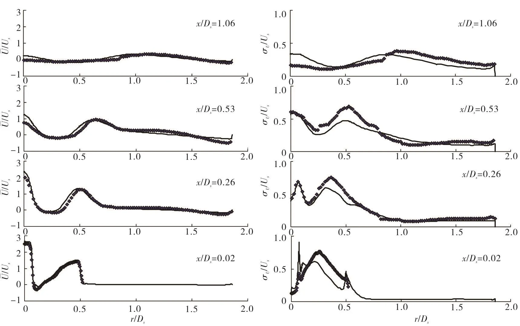
Fig.9 Comparison between LES predictions(line)and experimental data(symbols):left-mean axial velocity;right-mean rms in the axial direction[34].
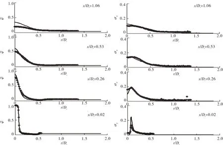
Fig.10 Comparison between LES predictions(line)and experimental data(symbols):left-mean scalar concentration;right scalar concentration fluctuation[34].
Unsteady, helically spiraling vortex structures observed experimentally are also visualized numerically.Further analysis of LES data clearly demonstrate that the origin of those structures is a rotating separation event inside the fuel injector itself as shown in Figure 11.It is evident from their studies[34-35]that the LES approach can not only capture the flow physics correctly but also provide instantaneous data which can be analyzed to improve the understanding of the flow physics involved.
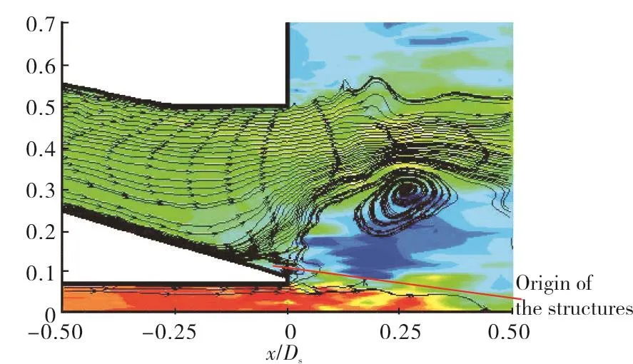
Fig.11 Instantaneous LES predicted streakline visualization on an x-r plane[35].
3.2 LES of a dump diffuser
Tang et al.[36]carried out numerical studies of the flow in a typical dump diffuser region of gas turbine combustors using both the RANS and LES approaches.Figure 12 shows a 2D view(x-rplane)of the computational domain and the mesh used in the study.The mesh is refined in near wall,free shear and reattachment regions with a total mesh point of about 0.8 million.
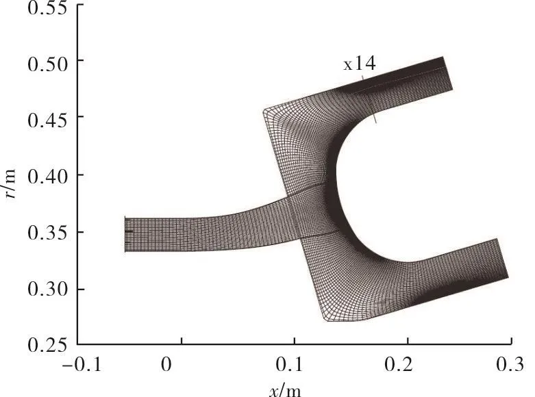
Fig.12 2D view(x-r plane)of computational domain and mesh[36].
Figure 13 presents contours of mean and instantaneous axial velocity, showing that the instantaneous flow field is very different from the averaged one.It can be seen clearly from the averaged flow field that four distinct recirculation zones exist whereas those are hardly observable from the instantaneous flow field.The instantaneous flow field shows that many small scale,turbulent structures exist and there are more than four recirculation zones and at different instances the size and shape of those recirculation zones are different too.
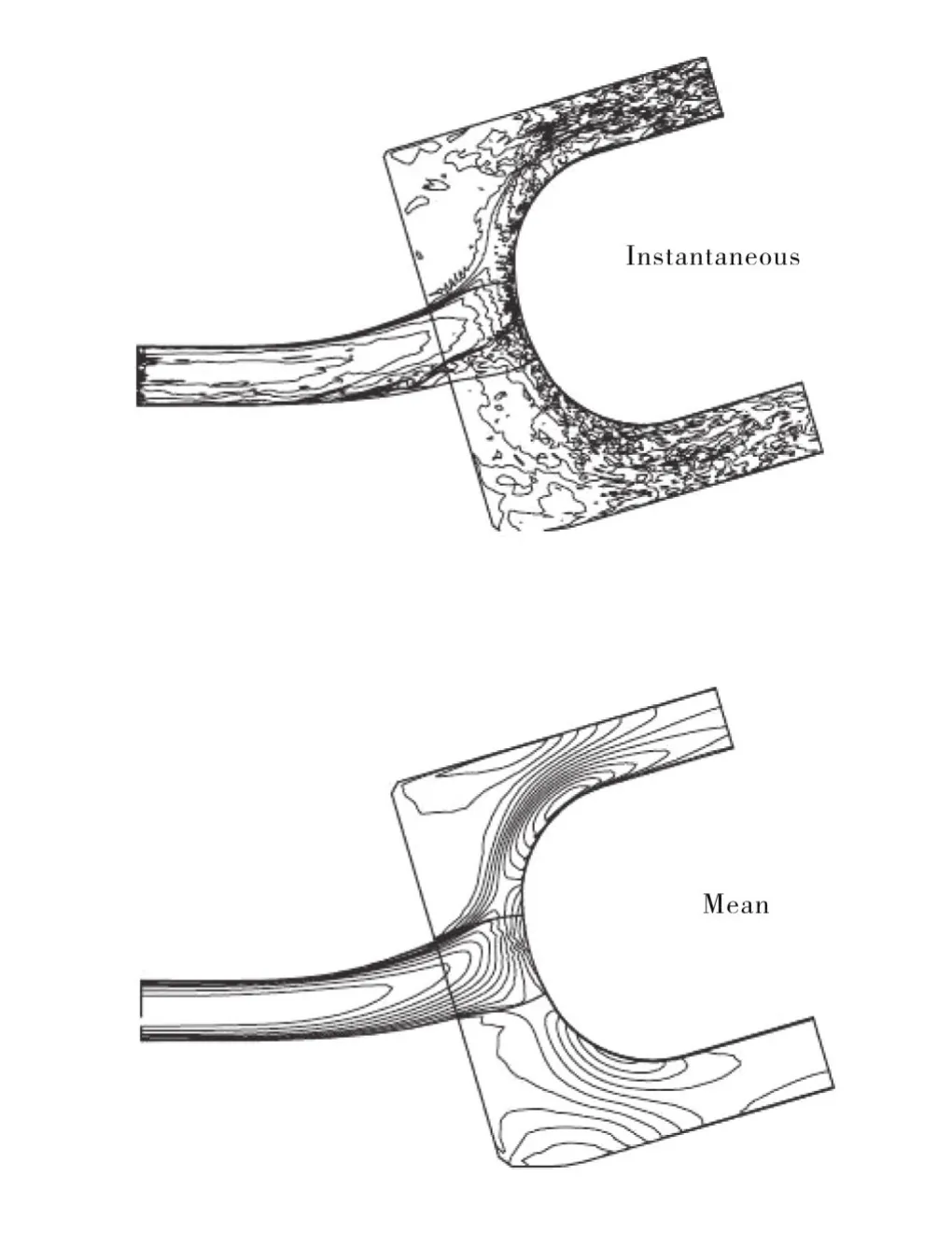
Fig.13 Contours of mean and instantaneous axial velocity on an x-r plane[36].
Figure14 showsthecomparison betweenthe predicted mean axial and transverse velocity profiles and experimental data at station x14(location of x14 is shown in Figure 12).The profiles are plotted against normalized co-ordinate r starting from 0(inner wall)to 1(outer wall).For the mean axial velocity,it can be seen that a good agreement has been obtained between the LES results and the experimental data and the RANS results using a Reynolds Stress Transport model(RST)are also close to the experimental data. However, the experimental data clearly show the existence of a small reverse flow region which is well captured by the LES approach but not by the RANS approach.In terms of the mean transverse velocity the LES results are closer to the experimental data.
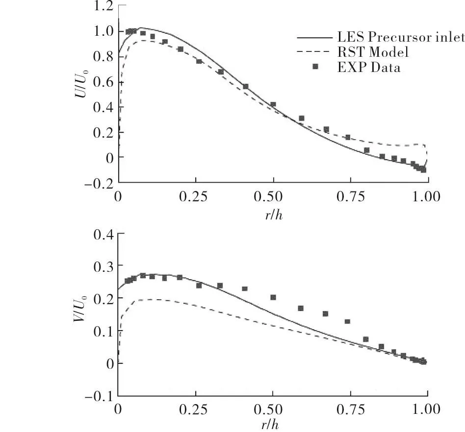
Fig.14 Mean axial and transverse velocity profiles at x14[36]
The rms values of velocity fluctuations in all three directions at the same location x14 are shown in Figure 15.A reasonably good agreement has been obtained between LES predictions(u-rmsandv-rms)and the experimental data,in terms of both the magnitude and the profile shape.However the RSM results are significantly lower than the experimental data,only about 50%of the measured values.In addition,for theu-rmsboth the LES predictions and the experimental data show clearly that there is a peak near the inner wall but the RANS approach fails to predict this peak.The LES predictions for thew-rmsagree well with the experimental data,especially the experimental data show a sharp rise of thew-rmsvalues near the outer wall and this peak is well captured by the LES approach.However,the RANS approach fails to capture this distinct peak completely as the RANS predictions are hugely different from the experimental data with the predicted value near the outer wall being only about 15%of the measured value.They concluded from their instantaneous flow field analysis that the sharp rise of thew-rmsvalues near the outer wall was mainly caused by large scale unsteady motion in this region associated with the movement of the instantaneous reattachment points,which the RANS approach would not be able to capture.
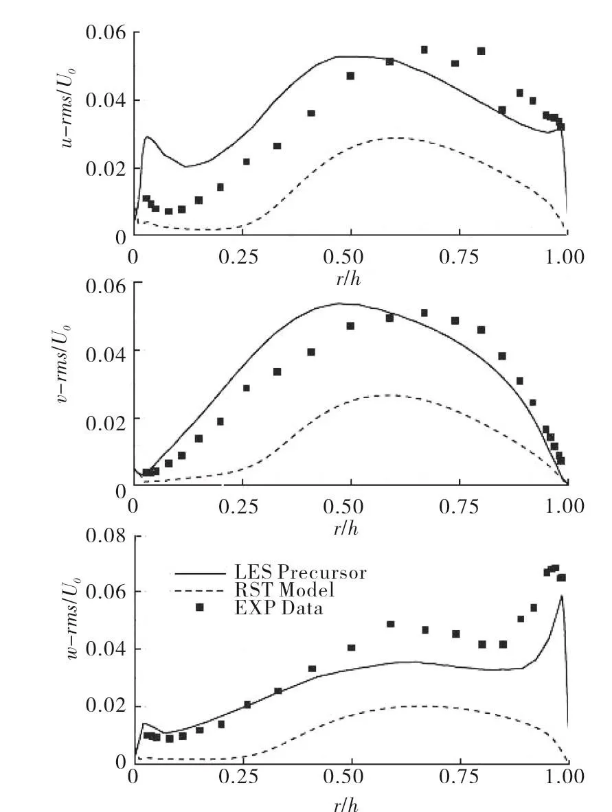
Fig.15 Profiles of u-rms,v-rms and w-rms at x14[36]
4 Discussion
It is evident that LES can not only provide accurate results in terms of the averaged variables but also more importantly it can supply all kinds of instantaneous information which can be processed/analyzed to improve/advance our understanding of flow physics involved.There is hardly any doubts now about the benefits of LES but practically compromise needs to be made between the benefits of LES and its computational cost.For example,in the flow situations where attached,turbulent boundary layer exist with relatively standard flow physics,which can be well predicted by the RANS approach.
For compressors operating at design conditions RANS/URANS can give reasonably accurate predictions but at off-design conditions it is necessary to employ LES.When separation and transition are present,which is usually the case for LPT flows,LES is needed to capture those flow phenomena whereas URANS could provide a fair reproduction of the periodic unsteady flow in HPT turbine passage in the absence ofseparation and transition.For the internal air system complex 3D flow structures exist and flow can also oscillate between quite different flow regimes with the possibility of vortex breakdown and hence LES is need.For combustor flows there are additional challenges such as liquid fuel injection,liquid fuel atomization and evaporation,largescale turbulent fuel air mixing,small scale molecular fuel air mixing,chemical reactions and so on,which are very difficult to be predicted accurately by RANS/URANS and therefore it is necessary to employ LES.Nevertheless it is worth pointing out that even with the current computing power LES is still very expensive computationally and hence so far there has not been any application of LES for a whole compressor or a whole turbine but LES of a whole gas turbine combustor has been carried out.In addition,for design engineers RANS is the still the main toolandwillremainsoforthenearfuture.
5 Challenges
5.1 Inflow BC
The proper specification of inflow boundary conditions(in particular thie characterization of inflow turbulence)is crucial in CFD and this is especially true in LES as three instantaneous velocity components are need at the inflow.However,those instantaneous velocity components are very rarely available from measurements and hence they need to be generated.It is hugely complex to generate inlet turbulence which should have proper turbulent characteristics such as stochastically varying,with a wide range of scales down to the smallest scale(spatially and temporally),compatible with the Navier Stokes equations,with the desired turbulence intensities,length scales,spectrum and so on.Many inflow boundary condition generation methods have been developed which can only generate inflow turbulence with certain properties and no robust methods available yet to generate inflow turbulence with all the desired characteristics[33].
5.2 Near wall modelling
It is essential to simulate near wall flow regions accurately is in order to correctly predict skin friction,heat transfer and so on.Ideally one needs to resolve the near wall flow structures with very fine mesh in LES but computationally this is very expensive and often becomes a bottleneck for LES applications in compressors and turbines.It is hence a big challenge to model the near wall flow properly in LES but despite the continuous efforts in the past decades a universal satisfactory model has not been developed.
5.3 SGS modelling
Mesh resolution is crucial in LES to simulate flow accurately,usually more than 80%of the turbulent kinetic energy needs to be resolved and less than 20% is modelled by a SGS model.Arguably one reason for the need of very good mesh resolution is because most SGS models used are based on a kind of'mixing length'model,which is very primitive compared with turbulence models developed under the RANS approach.The requirement of good mesh resolution makes LES very expensive and as a result of this many hybrid RANS/LES approaches has been developed but with some fundamental questions unanswered.Therefore,the author would argue for developing a more advanced and robust SGS model under the LES framework so that the mesh resolution requirement could be relaxed.
5.4 Compressible flows
Much lessworkhasbeendoneinLES for compressible flows compared with LES for incompressible cases and there remain many challenges/issues in this area.Transonic flows often appear in gas turbine flows with the presence of shock waves which require extra efforts to capture the shock in a stable and accurate manner since shock waves are most commonly treated by low-order methods,often employing upwind schemes,which are not really appropriate for LES.In addition SGS modelling for compressible flows will be more complicated and any SGS model developed for incompressible flows may not work well.Much more work is needed for further development/validation of LES in this area.
5.5 Combustion
Combustion processin gasturbinesishugely complex,usually involving liquid fuel injection,liquid fuel atomization,droplets breakup and evaporation,large scale turbulent fuel air mixing,small scale molecular fuel air mixing,chemical reactions,and turbulence/chemistry interactions.Chemical reactions occur on very small scales(usually smaller than LES mesh)and hence is modelled by a SGS combustion model.Although much progress has been made in the past two decades in the development/validation of LES for gas turbine combustion it is still a big challenge to simulate the combustion process accurately.
6 Conclusions
A brief review on the applications of LES in turbomachinery flows has been presented in this paper,demonstrating the increase and successful applications in this area.Applications of LES for two gas turbine combustor related flow cases have been reviewed in more detail,showing the capability of LES in capturing important flow features and the superiority of LES over the RANS approach.Several major challenges for LES development and its application in gas turbines have been briefly discussed.
It is evident that the traditional computational approach, RANS/URANS, has its limitations in predicting inherently unsteady and complex gas turbine flows accurately.In certain cases it can fail to capture some essential flow features completely.Hence for accurate predictions a high fidelity simulation approach is needed and LES is a suitable choice since DNS is still far too expensive and not feasible for engineering flow simulations.Nevertheless,LES is still far more expensive than RANS and practically compromise needs to be made between the benefits of LES and its computational cost.
There is no doubt that LES will become more and more widely used in gas turbine flow simulations.However, significant challenges such as proper specification/construction of realistic turbulent inflow boundary conditions still remain and there is a long way to go before LES can replace the RANS approach as a design tool.
[1]Tucker,P.G.(2011).Computation of unsteady turbomachinery flows:Part 1-Progress and challenges.Progress in Aerospace Sciences,Vol.47,pp.52-545.
[2]Tucker,P.G.(2011).Computation of unsteady turbomachinery flows:Part 2-LES and hybrids.Progress in Aerospace Sciences,Vol.47,pp.546-569.
[3]You D.,Mittal R.,Wang M.,Moin P.(2004).Computational methodology for large-eddy simulation of tip-clearance Flows.AIAAJournal,Vol.42,pp.271-279.
[4]You D.,Mittal R.,Moin P.,Wang M.(2004).Effects of tip-gap size on the tip-leakage flow in a turbomachinery cascade.Physics of Fluids,Vol.18,pp.105102.1-105102.14.
[5]You D.,Wang M.,Moin P.,Mittal R.(2007).Large-eddy simulation analysis of mechanism for viscous losses in a turbomachinery tip-clearance flow.Journal of Fluid Mechanics,Vol.586,pp.177-204.
[6]Lee,S.,Kim,H.,Runchal,A.(2004).Large eddy simulation of unsteady flows in turbomachinery.Proceedings of the Institution of Mechanical Engineers,Part A:Journal of Power and Energy,Vol.218,pp.463-75.
[7]Hah,C.(2009).Large eddy simulation of transonic flow field in NASA rotor 37.In:Proceedings of the 47th AIAA aerospace sciences meeting,Paper no.2009-1061,Orlando,Florida.
[8]Hah,C.,Voges,M.,Mueller,M.,Schiffer,H.P.(2009).Investigation of unsteady flow behaviour in transonic compressor rotors with LES and PIV measurements,ISABE.Paper no.ISABE-2009-02.
[9]Lardeau,S.,Leschziner,M.,Zaki,T.A.(2012).Large eddy simulation of transitional separated flow over a flat plate and a compressor blade.Flow Turbulence and Combustion,Vol.88,pp.19-44.
[10]McMullan,W.A.,Page,G.J.(2012).Towards large eddy simulation of gas turbine compressors.Progress in Aerospace Sciences,Vol.52,pp.30-47.
[11]Hah,C.,Hathaway,M.,Katz,J.(2014).Investigation of unsteady flow field in a low-speed one and a half stage axial compressor:effect of tip gap size on the tip clearance flow structure at near stall operation.ASME Turbo Expo:Turbine Technical Conference and Exposition,Paper No.GT2014-27094.Düsseldorf,Germany.
[12]Gourdain,N.(2015).Prediction of the unsteady turbulent flow in an axial compressor.Part 1:Comparison of unsteady RANS and LES with experiments.Computers&Fluids,Vol.106,pp.119-129.
[13]Gao,F.,Ma,W.,Zambonini,G.,Jérôme Boudet,J.,Ottavy,X.,Lu,L.,Shao,L.(2015).Large-eddy simulation of 3-D corner separation in a linear compressor cascade.Physics of Fluids,Vol.27,pp.085105-1-21.
[14]Scillitoe,A.,Tucker,P.G.,Adami,P.(2016).Numerical investigation of three-dimensional separation in an axial flow compressor:the influence of free-stream turbulence intensity and end wall boundary layer state.ASME Turbo Expo:Turbomachinery Technical Conference and Exposition,Paper No.GT2016-57241.Seoul,South Korea.
[15]R.Mittal,R,Venkatasubramanian,S.,Najjar,F.M.(2001).Large-eddy simulation of flow through low-pressure turbine cascade.Proceedings of the 15th AIAA Computational Fluid Dynamics Conference,Paper No.AIAA 2001-2560.Anaheim,USA.
[16]Michelassi,V.,Wissink,J.G.,Rodi,W.(2003).Direct numerical simulation,large eddy simulation and unsteady Reynoldsaveraged Navier-Stokes simulations of periodic unsteady flow in a low-pressure turbine cascade:A comparison.Proceedings of the Institution of Mechanical Engineers,Part A:Journal of Power and Energy,Vol.217,pp.403-411.
[17]Raverdy,B.,Mary,I.,Sagaut,P.(2003).High-resolution large-eddy simulation of flow around low-pressure turbine blade.AIAAJ,Vol.41,pp.390-397.
[18]Sarkar,S.,Voke,P.R.(2006).Large-eddy simulation of unsteady surface pressure over a LP turbine due to interactions of passing wakes and inflexional boundary layer.ASME,J Turbomachinery,Vol.128,pp.221-231.
[19]Sarkar,S.(2009).Influence of wake structure on unsteady flow in a low pressure turbine blade passage.Journal of Turbomachinery,Vol.131,pp.041016-1-14.
[20]Matsuura,K.,Kato,C.(2006).Large-eddy simulation of compressible transitional cascade flows with and without incoming free-stream turbulence.JSME International Journal,Series B,Vol.49,pp.660-669.
[21]Jimbo,T.,Biswas,D.,Yokono,Y.,Niizeki,Y.(2008).A highorder LES turbulent model to study unsteady flow characteristics in a high pressure turbine cascade.ASME Turbo Expo:Power for Land,Sea and Air,Paper No.GT2008-51458.Berlin,Germany.
[22]Medic,G.,Sharma,O.(2012).Large-eddy simulation of flow in a low-pressure turbine cascade.ASME Turbo Expo:Turbine Technical Conference and Exposition,Paper No.GT2012-68878.Copenhagen,Denmark.
[23]Papadogiannis,D.,Duchaine,F.,Sicot,F.,Gicquel,L.,Wang,G.,Moreau,S.(2014).Large eddy simulation of a high pressure turbine stage:Effects of sub-grid scale modeling and mesh resolution.ASME Turbo Expo:Turbine Technical Conference and Exposition,PaperNo.GT2014-25876.Düsseldorf,Germany.
[24]Cui,J.,Rao,V.N.,Tucker,P.(2016).Numerical investigation of contrasting flow physics in different zones of a high-lift lowpressure turbine blade.Journal of Turbomachinery,Vol.138,pp.011003-1-10.
[25]Sun,Z.,Lindblad,k.,Chew,J.,Young,C.(2006).LES and RANS investigations into buoyancy-affected convection in a rotating cavity with a central axial through flow.ASME Turbo Expo:Power for Land,Sea,and Air,Paper No.GT2006-90251.Barcelona,Spain.
[26]Andersson,H.I.,Lygren,M.(2006).LES of open rotor-stator flow.International Journal of Heat and Fluid Flow,Vol.27,pp.551-557.
[27]Tuliszka-Sznitko,E.,Zielinski,A.,Majchrowski,W.(2009).LES of the non-isothermal transitional flow in rotating cavity.International Journal of Heat and Fluid Flow,Vol.30,pp.534-548.
[28]Viazzo,S.,Poncet,S.,Serre,E.,Randriamampianina,A.,P.Bontoux,P.(2012).High-order large eddy simulations of confined rotor-stator flows.Flow,Turbulence&Combustion,Vol.88,pp.63-75.
[29]Onori,M.,Amirante,D.,Hills,N.J.,Chew,J.(2016).LES validation for a rotating cylindrical cavity with radial inflow.ASME Turbo Expo:Turbomachinery Technical Conference and Exposition,Paper No.GT2016-56393.Seoul,South Korea.
[30]O’Mahoney,T.S.D.,Hills,N.J.,Chew,J.W.,Scanlon,T.(2011). Large-eddy simulation of rim seal ingestion.Proceedings of the Institution of Mechanical Engineers,Part C:Journal of Mechanical Engineering Science,Vol.225,pp.2881-2891.
[31]Gao,F.,Chew,J.,Beard,P.,Amirante,D.,Hills,N.J.(2017).Numerical Studies of turbine rim sealing flows on a chute seal configuration.Proceedings of 12th European Conference on Turbomachinery Fluid dynamics & Thermodynamics,Stockholm,Sweden.
[32]Gicquel,L.Y.M.,Staffelbach,G.,Poinsot,T.(2012).Large eddy simulations of gaseous flames in gas turbine combustion chambers.Progress in Energy and Combustion Science,Vol.38,pp.782-817.
[33]Yang,Z.(2015).Large-eddy simulation:Past,present and the future.Chinese Journal ofAeronautics,Vol.28,pp.11-24.
[34]Dianat,M.,Yang,Z.,McGuirk,J.J.(2007).LES of fluid mechanics and scalar mixing in gas turbine fuel injectors.Proceedings of Large-Eddy Simulation for Advanced Design and Combustion Systems,Rouen,France.
[35]Midgley,K.,Dianat,M.,Spencer,A.,Yang,Z.,McGuirk,J.J.(2007).Scalar measurements and unsteady simulations in high swirl confined flows.Proceedings of the 9th International Gas Turbine Conference,Paper No.IGTC2007-ABS-79,Tokyo,Japan.
[36]Tang,G.,Yang,Z.,McGuirk,J.J.(2004).Numerical method for Large Eddy Simulation in general co-ordinates.Int.Journal for Numerical Methods in Fluids,Vol.46,pp.1-18.