Test Research of Seepage Monitoring Based on Distributed Optical Fiber
2018-05-25,,,,,,
, , , , , ,
1.Department of Civil Engineering,Nanjing University of Aeronautics and Astronautics,Nanjing 210016,P.R.China;
2.Taizhou Water Conservancy Bureau,Taizhou 225300,P.R.China
0 Introduction
Levees have a lot of characteristics such as long lines,wide distribution and dense population in the protection segment.So once a levee collapses,it will cause serious disasters.Seepage is one of the important dam damage forms which are influenced by the construction quality,embankment material,creature-ablation and water level changes.According to the statistics of earth dam destroy crash[1],the percentage of seepage damage is 45%,seriously endangering the dam safety.Therefore,it is of great significance to monitor dam seepage in real time.Distributed optical fiber temperature sensing(DTS)has the advantages of real-time monitoring,low cost,simple construction,lightning protection,wide monitoring range,and resistance to corrosion,high pressure,high temperature,and electromagnetic interference,which shows its broad application prospects in seepage monitoring[2].
At present,there are a few studies on the seepage monitoring based on distributed optical fiber.Alain et al.[3]studied quantitative relationship between seepage velocity and optical fiber temperature of sandy soil utilizing DTS combined with indoor model test,and concluded that there is a linear relationship between optical fiber temperature and logarithm of the heating time in sandy soil.Marc et al.[4]set up an automatic alarm system to monitor Berlin 55km long underground brine pipeline leakage and determined the leakage location through the changes of temperature curve.Andrea et al.[5]set up an automatic alarm system to monitor Canada's new Brunswick 30km long brine pipeline leakage and summarized that the factors affecting the temperature changes of optical fiber were seasonal temperature changes,pipeline embedment depth,soil or backfill soil types,soil moisture content,terrain conditions and so on.Zhu et al.[6]proposed a seepage flow simulator and monitoring system based on DTS.The simulator equipment can monitor various embankments with different boundary conditions,such as temperature,distributions of soakage line and scales.Xiao et al.[7]deduced the theoretical solution of seepage velocity combining the theory of porous media heat transfer and DTS sensing principle.Based on thermal equilibrium theory and the relationship between the soil temperature changes surrounding the dam body and the leakage velocity,Dong et al.[8]established a mathematical physical model,discussed the determination method of seepage velocity under two different flow conditions (laminar and turbulent),and verified the correctness of the mathematical physical model combining with basic experiment results of the fiber optic monitoring from Munich University of Science and Technology.Gu et al.[9]established a mathematical temperature field model of earth dam feedback seepage field,and verified the model combining with the distributed fiber temperature measurement test results of indoor homogeneous earth dam model.Su et al.[10-11]deduced heat transfer theoretical model of seepage monitoring and verified the feasibility of distributed optical fiber monitoring seepage through establishing experimental model to simulate the seepage.At present,the technologies of distributed optical fiber temperature sensor used in seepage monitoring are mainly focused on seepage positioning.The quantitative seepage monitoring is still under research.There are no mature results which can be used in practice.The influence factors of soil infiltration (e.g.,degree of compaction,etc.)considered in the past experimental analysis are not perfect.Therefore,stud-ying the seepage quantitative monitoring based on the DTS has important theoretical significance and engineering application value.
1 Seepage Monitoring Principle Based on Distributed Optical Fiber Temperature Sensing
When an optical pulse is launched into an optical fiber,some backscattered signals come back to the input end.There are three main types of scattering,and Raman scattering is one of them.Raman scattering in fiber consists of anti-Stokes and Stokes signals,and the ratio of the anti-Stokes and Stokes signals backscattered from within the fiber is a function of the absolute temperature of the scattering point.Hence,the Raman distributed temperature sensor uses the ratio of anti-Stokes and Stokes signal intensities to calculate the temperature.The ratio is given by

whereIasis the anti-Stokes intensity;Isthe Stokes intensity;αthe temperature-related coefficient;pPlanck′s constant;cthe velocity of light;wthe wavenumber shift for the fiber material;kthe Boltzmann constant;Tthe absolute temperature of the scattering point in the fiber.
The seepage monitoring technology principle based on TDS is similar to the convection heat transfer process with swept round line heat source in the porous media in the thermodynamics.The thermal conductivity coefficient of complex porous mediums (including water and solids)is taken as a whole unified porous medium in the analysis process of heat transfer mode.Therefore,the heat transfer process of porous medium with optical fiber can be converted to that of a single material with fiber.This process can be shown as

whereQλis the heat transfered to the surrounding medium in the process of heat transfer by the op-tical fiber;λthe coefficient of thermal conductivity after conversion;Athe heat transfer area;Tthe temperature andxthe distance.
The thermal convection will occur when the fluid contacts with the optical fiber.Newton cooling formula can be used as the basic formula for expression

whereQvis the convective heat transfer of optical fiber and water;Aathe convective heat transfer surface area of optical fiber and water;hthe heat transfer coefficient;Tsthe surface temperature of optical fiber andTfthe temperature of water.
Considering the heat transfer and convection during the seepage process,the seepage velocity formula calculation theory based on DTS can be deduced and expressed as[12]

wherePis the heating power;Ithe current flowing through metal armoured the optical fiber;Rthe resistance of metal armoured;rthe radius of armoured optical fiber;lthe length of armoured optical fiber;θthe temperature changes;ethe porosity of porous media;uthe seepage velocity;λsthe thermal conductivity coefficient of solid particles;nthe constant of swept round;andDa composite constant[6].
Eq.(4)shows that the optical fiber heating power isntimes polynomial of seepage velocity.There exist related researches about the value range ofnin the relation between heating power and seepage velocity,but the scopes are not the same.The value range ofnshould be determined combining with the analysis of test results because of the soil medium complexity.It′s a linear relationship between the heating power and the optical fiber temperature.So the optical fiber heating temperature isntimes polynomial of seepage velocity,namely

whereΔTis heating temperature of the optical fiber;k,a,bare the undetermined constants;uis the fluid seepage velocity.
2 Seepage Monitoring Test Based on Distributed Optical Fiber Temperature Sensing
2.1 Test model
The tank for the test is made of 2cm thick solid wood.The size of the tank is 1m×0.5m×0.6m,as shown in Fig.1.The waterproof cloth is pasted in the tank and the waterproof coating is brushed in the tank to prevent the sink from leaking.The faucet is installed at the bottom of the tank to control the water yield.The 10cm gravel,filter cloth,10cm soil,optical fiber and 10cm gravel are embedded in the tank from down to up in turn,as shown in Fig.2.The optical fiber is decorated as serpentine,as shown in Fig.3.The optical fiber arrangement spacing is 6cm.The research objects in the test are soil mediums including fine sand and the mixture of fine sand and clay soil.The quality proportions of fine sand and clay soil are 4∶1and 3∶2,respectively[13].
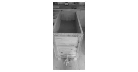
Fig.1 Test tank

Fig.2 Soil arrangement
2.2 Test method

Fig.3 Optical fiber arrangement
In the test,the temperature measurement for seepage detection is performed by Sentinel DTS in conjunction with a heatable armoured optical fiber.The Sentinel DTS machine is a product of British Sensornet Company.The heatable armoured optical fiber with the diameter of 3mm consists of a multimode sensing optical fiber,armoured wire and an outer sheath[14].The heating method is adopted to monitor the seepage.A stable voltage is needed to apply to heat the armoured wire,which is taken as a resistance wire.The heating system consists of an alternating current power source with an adjustable voltage and the load resistance wire.The voltage regulator adopted in the test is single phase regulator TDGC2-5.The working voltage ranges from 20Vto 250V.The rated current is 20Aand any voltage within 250Vcan be put out.The resistance of armoured optical fiber is 17.5Ω/m.The heating power is 19.62W/m to ensure that the average temperature rise of fiber can achieve 15 ℃ after heating for 16min.The water level in the tank is kept at a fixed location during the whole test process.The water switch should be calibrated before the test to ensure that the water yield is close to each other when the opening degree of the switch is the same.The soil is compacted by using static load pressure.With the aid of irrigation method,the soil compaction degree can be measured.Six seepage velocities corresponding to different opening degree of the switch are measured under every compaction degree.DTS is used to measure the temperature changes of the optical fiber during the whole heating process under various seepage velocities.The average temperature rise after heating 10—15min is taken as the reference value of optical fiber heating temperature level.To ensure that the seepage flow can supply outlet water yield,each soil must be penetrated after the change of soil compaction.The seepage flow is enough to supply water yield when the water level in the sink is at the fixed location,if air bubbles do not emerge and the water velocity is not reduced over a period of time.
3 Analysis of Test Result
3.1 Relationship between seepage velocity and optical fiber temperature rise
The average velocity through the soil profile can be calculated based on the test design principle.All kinds of soils under different compaction degree of seepage velocity relation with fiber heating temperature was obtained according to the test results,as shown in Fig.4.
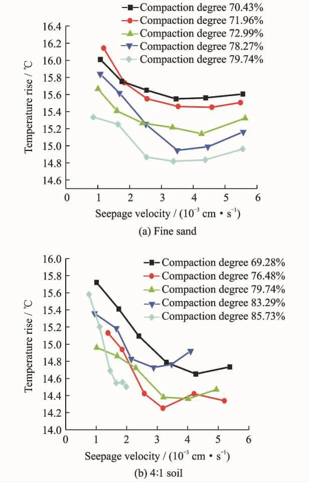
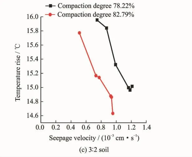
Fig.4 Relationship between seepage velocity and optical fiber temperature rise for different soils and compaction degree
It is easy to find that the optical fiber heating temperature rise with the seepage velocity is a quadratic curve relationship from Figs.4(a,b).The relationship between seepage velocity and temperature rise is represented asΔT=av2+bv+c.HereΔTis the optical fiber heating tempera-ture rise andvis the seepage velocity.The fitting parameters of the curve are shown in Table 1.The fitting index between seepage velocity and heating temperature rise is above 0.9from the curve fitting results in Table 1,which means optical fiber heating temperature rise with seepage velocity is a quadratic curve relationship for the high fitting degree.With the increase of seepage velocity,the heating temperature decreased firstly and then increased,as shown in Figs.4(a,b).For the quality proportion of fine sand and clay is 3∶2,the seepage flow is small when the compaction degree is more than 85%due to the increase of clay composition in the soil and the decrease ofpermeability.There are only two sets of data,as shown in Fig.4(c),due to the little velocity difference between different degree of switch.With the increase of seepage velocity,the heating temperature decreased without the rising part,as shown in Fig.4(c).
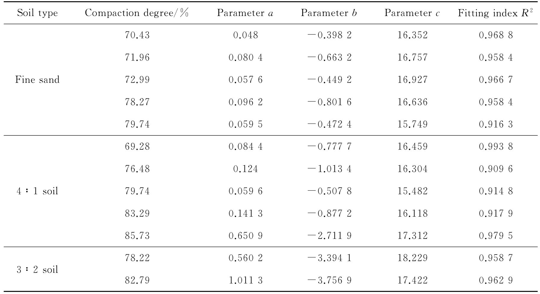
Table 1 Fitting index between seepage velocity and heating temperature rise
The test mechanism can be analyzed through fluid outside swept round tube heat transfer principle[11].When the fluid sweeps outside the round tube,the starting point of the flow around detached namely separation point will appear at the location where the pipe surface velocity gradient is zero.Vortexes formed in the boundary layer of reverse flow will destroy the normal boundary layer flow.The flow condition of wall boundary layer determines the characteristics of heat transfer.The distribution of round tube wall local surface heat transferNuφis shown in Fig.5.The curve shows that the decrease of local surface heat transfer coefficient will lead to the decreases of pipe average surface heat transfer coefficient because of the increase of laminar boundary layer thickness from the tube front stagnation pointφ=0°.
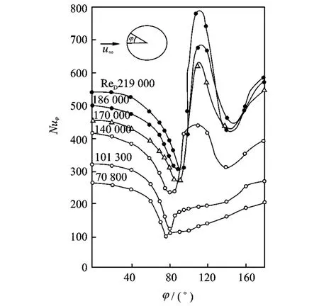
Fig.5 Distribution of round tube wall local surface heat transfer Nuφ
The two working conditions of the lowest fluid Reynolds number Re always maintain laminar flow before the separation point in Fig.5and the lowest value ofNuφappears near the separation point.Then with the chaotic movement of vortex in the detached area,the value ofNuφincreases.The turbulent flow happens when the other conditions of high Reynolds number has detached in the wall boundary layer.The two troughs ofNuφcurve are the transition zone from laminar flow to turbulent flow and the location where the turbulent boundary layer detaches the wall,respectively.The value ofφdepends on the value of Reynolds number in Fig.5.The value of Reynolds number depends on the value of seepage velocity in the test.Therefore,the greater the seepage velocity,the greater the value ofφwill be.
It is easy to find that the value ofNuφhas little change in the range ofφfrom Fig.5,which has little impact on fiber surface average heat transfer coefficient.The maximum seepage velocity corresponding to the compaction degree of fine sand and 4∶1soil is about five times of the initial seepage velocity.There exists obvious difference between the maximum and the initial value of seepage velocity.The values ofφcorresponding to different seepage velocities and the values ofNuφexist obvious change,which will lead to violently a decrease in the optical fiber average surface heat transfer coefficient.The heat accumulation caused by the decreases of optical fiber average surface heat transfer coefficient may be greater than the heat loss caused by the increases of seepage velocity.Therefore,the fiber heating temperature rise will be bigger when the seepage velocity is large.The seepage velocity is small because of the poor permeability of 3∶2soil.The difference of the values ofNuφcorresponding to the maximum and initial value of seepage velocity is small because of little difference of the maximum and initial seepage velocity.The heat accumulation caused by the decreases of optical fiber average surface heat transfer coefficient may be less than the heat loss caused by the increases of seepage velocity.Therefore,the temperature rise keeps falling.It is reasonable to adopt a quadratic curve to analyze the relationship between seepage velocity and heating temperature of 3∶2soil.
3.2 Effect of soil compaction degree on optical fiber temperature
The compaction degree is one of the main control targets of actual construction quality in project construction.It determines the internal granule structure arrangement and the porosity of soil,which has important influence on the permeability and heat conduction performance of soil.The compaction degree has different influence on different soils.The relationships between compaction degree and optical fiber temperature rise of fine sand,4∶1soil and 3∶2soil are shown in Fig.4.
As can be seen from Fig.4(a),the optical fiber heating temperature rise keeps failing with the increase of compaction degree of fine sand.The difference of optical fiber temperature rise is quite small and uniform because of the quite uniform sandy medium and the quite small compaction degree.The compression degree has a quite obvious influence on the permeability of the soil containing clay,as shown in Fig.4(b).Therefore,the distribution of the curve is less uniform than that of fine sand.The optical fiber heating temperature rise is on the decline with the increase of the compaction degree,while optical fiber heating temperature rise exists a certain fluctuation because of obvious difference among seepage velocities corresponding to different compaction degree.There exist only two curves because of the quite large clay content of the soil in Fig.4(c)when the compaction degree is large.It is easy to find that optical fiber heating temperature will drop with the increase of the compaction degree from the two curves.The increase of compaction degree changes the proportion of solid particles and wa
ter in the soil,which will increase the content of solid particles in per unit volume of soil.The thermal conductivity coefficient of solid particles is bigger than that of water.Therefore,the soil thermal conductivity performance enhances with the increase of compaction degree and the optical fiber heating temperature rise will gradually decline.It is easy to find that optical fiber heating temperature rise embedded in the soil will gradually decline with the increase of compaction degree through analyzing all the above situations.Thus,soil compaction should be considered in experimental research and engineering application in the future.
3.3 Effect of soil composition on optical fiber temperature
The soil is in saturated condition in the test.The main factors affecting fiber heating temperature rise are the heat conduction performance,the porosity and dry density of mineral solids.The mineral solids containing in the soil are the main part,whose heat conduction performance determines the whole heat conduction performance of soil.The porosity determines the water content and the distribution of seepage channels of soil has important influence on the fiber heating temperature rise.The dry density is equivalent to the compaction degree in the test.The compaction degree affects both the permeability and the porosity of the soil.It′s easy to find that the dry density has little impact on the permeability,but it has an important impact on the soil containing large amount of clay.The greater the clay contains,the greater affects will be.Therefore,the soil medium has important effects on fiber heating temperature rise.The seepage monitoring programme should be studied according to different soil types in actual project monitoring.
4 Conclusions
This paper deduces the mathematical model of seepage monitoring through the test study of seepage quantitative monitoring based on distributed optical fiber.The following conclusions can be drawn through the indoor model test.
(1)The optical fiber heating temperature rise with seepage velocity shows a quadratic curve relationship while monitoring seepage through heating method.There are different quantitative relationships corresponding to different compaction degree.The reasonable quantitative relationships between optical fiber heating temperature rise and seepage velocity need to be selected to monitor seepage velocity according to actual situations in practical engineering.
(2)The compaction degree of soil has important effects on optical fiber heating temperature rise.The test results show that optical fiber heating temperature rise is on the decline with the increase of compaction degree.Therefore,the relationship between compaction degree and optical fiber heating temperature rise needs to be considered in future research and engineering application.
(3)Different soils have different physical indicators,which leads to complex effects on optical fiber heating temperature rise for the soils.The test plan needs to be made to study quantitative relationships according to different soil conditions of each project in practical engineering.
The seepage monitoring technology based on DTS has advantages of low cost,universal coverage,accurate positioning and so on.So it has a broad application prospect in pipeline engineering and levee engineering leakage monitoring.The realization of seepage quantitative monitoring technology exists many problems to be solved at the same time.Therefore,the seepage monitoring research based on DTS has important theoretical significance and engineering application value.
Acknowledgements
This work was supported by the Water Conservancy Science and Technology Project of Jiangsu Province(Nos.2012088,2013093).
[1] QIAN Jiahuan,YIN Zongze.Earthwork principle and calculation[M].Beijing:China Water Conservancy and Hydropower Press,1995.(in Chinese)
[2] Lin J,WU J.Optical fiber grating monitoring for reinforcement corrosion[J].Journal of Nanjing University of Aeronautics & Astronautics,2008,40(3):395-398.(in Chinese)
[3] ALAIN C,BENOIT C,JEAN L et al.Water leakage detection using optical fiber at the peribonka dam[C]//Proceedings of the Seventh International Symposium on Field Measurements in Geomechanics.New York:ASCE,2007(175):1-12.
[4] MARC N,BERNHARD V,FABIEN B et al.Leakage detection using fiber optics distributed temperature rise monitoring[C]//The Proceedings of the 11th SPIE Annual International Symposium on Smart Structures and Materials.San Diego,California:ASCE,2004:18-25.
[5] MYLES A.Permanent leak detection on pipes using a fibre optic based continuous sensor technology[C]//Pipelines Conference 2011.Seattle, Washington,USA:American Society of Civil Engineers,2011:744-754.
[6] ZHU Pingyu,LUC THEVENAZ,LENG Yuanbao,et al.Design of simulator for seepage detection in an embankment based on distributed optic fibre sensing technology[J].Chinese Journal of Scientific Instrument,2007,28(3):431-436.(in Chinese)
[7] XIAO Henglin,BAO Hua,WANG Cuiying,et al.Research on theory of seepage monitoring based on distributed optical fiber sensing technology[J].Rock and Soil Mechanics,2008,29(10):2794-2798.(in Chinese)
[8] DONG Haizhou,KOU Dingwen,PENG Huyue.Computational model for dam leakage velocity in concentrated passage based on distributed optic fiber temperature sensing system[J].Chinese Journal of Geotechnical Engineering,2013,35(9):1717-1721.
[9] GU Yanchang,WANG Shijun,PANG Qiong,et al.Feasibility of temperature field feeding back seepage field for earth dams[J].Chinese Journal of Geotechnical Engineering,2014,36(9):1721-1726.
[10]SU Huaizhi,KANG Yeyuan.Design of system for monitoring seepage of levee engineering based on distributed optical fiber sensing technology[J].International Journal of Distributed Sensor Networks,2013(3):1-10.
[11]SU Huaizhi,HU Jiang,YANG Meng.Dam seepage monitoring based on distributed optical fiber temperature system [J].IEEE Sensors Journal,2014,15(1):9-13.
[12]ZHANG Ximin,REN Zepei,MEI Feiming.Heat transfer [M].Beijing:China Building Industry Press,2001.(in Chinese)
[13]ZHOU Bobing,XU Guolong,ZHAO Xinming,et al.Seepage monitoring test based on distributed optical fiber temperature sensor technology[J].Water Resources and Power,2015,10:104-107.(in Chinese)
[14]LIU Rongmei,XIAO Jun,LIANG Dakai,et al.Performance improvement method of CFRP with embedded optical fiber[J].Transactions of Nanjing University of Aeronautics and Astronautics,2015,32(3):261-267.
杂志排行
Transactions of Nanjing University of Aeronautics and Astronautics的其它文章
- Simulation Tools for a Fiber-Optic Based Structural Health Monitoring System
- Segmentation of Thermographic Sequences in Frequency Modulated Thermal Wave Imaging for NDE of GFRP
- Non-destructive Evaluation of Absolute Stress in Steel Members Using Shear-Wave Spectroscopy
- Quantitative Rectangular Notch Detection of Laser-induced Lamb Waves in Aluminium Plates with Wavenumber Analysis
- Effect of Thermal Treatment on CFRP Parts Before and After Adhesive Bonding
- Full Wavefield Analysis for Damage Assessment in Composite Materials
