Effect of Thermal Treatment on CFRP Parts Before and After Adhesive Bonding
2018-05-25,,,
, , ,
Institute of Fluid Flow Machinery,Polish Academy of Sciences,80-231Gdansk,Poland
0 Introduction
The research presented here is focused on non-destructive assessment of surface before bonding and the adhesive bonds of carbon fibre reinforced polymer(CFRP)parts.The structural joints should ensure safe usage of a structure.The performance of adhesive bonds depends on the properties of the surfaces to be joint.Some modifications of the surface may lead to weak bond that cannot carry the desired load.It is important to have a reliable tool that allows to assure the quality of the surface prepared for bonding.One of the promising methods for surface assessment is the electronic nose[1].Apart from the problem of surface assessment,another important subject is to assess the bonded part.The examples of techniques investigated for this task are electromechanical impedance[2]and laser-induced shock waves[3].The research reported here aims at nondestructive assess of the surface with pre-bond modifications related to conditions encountered during the in-service life of composite parts.The pre-bond modifications have an influence on the fracture toughness of the CFRP bonded joints.Markatos et al.studied the influence of pre-bond release agent contamination and moisture absorption on mode-I fracture toughness of CFRP bond-ed joints[4].A mode-I double cantilever beam specimen was used to determine the mode-I energy release rate(GIC)referring to crack initiation.The lowest considered contamination with release agent did not affect the bond.The increase of the contamination caused at least 60%drop of the GIC value in relation to the reference case.The pre-bond thermal treatment results reported in the literature show that the GIC value decreases by 10%and 13%for treatment at 190and 200℃,respectively[5].In the case of treatment at 210℃the increase by 9%was observed[5].The de-icing fluid contamination has a negative effect on both mode I and mode II fracture toughness of the bonded joints[6].With increasing the contamination level,the mode I and mode II critical energy release rates decrease.Published investigations on contamination with Skydrol hydraulic fluid showed that there is a considerable influence on the fracture toughness of the joints[7]:It decreases by 27%.
The intention of this paper is to study preand post-bond effects of thermal treatment.The laser induced fluorescence (LIF)method was used for assessment of the surface condition.The LIF method is a spectroscopic method that can be potentially applied to large surface material analysis[8].The detection of kerosene and hydraulic fluid on CFRP surface was reported before[9].Good results were obtained for 266nm excitation.In other work[10]three wavelengths were studied(266,355and 532nm).Detection of hydraulic fluid,release agent and moisture contaminations,and thermal treatment were presented.It was shown that at 532nm the thermal treatment can be easily distinguished from the remaining cases.Moreover,it was presented that samples treated at 190℃,200℃,and 210℃ were characterized by increasing LIF intensity and could be distinguished from each other and from the referential samples.In research reported here we present results for higher temperatures(220℃,260℃and 280℃).Moreover,a combined case is considered with thermal treatment and surface contamination with de-icing fluid.The adhesive bonding is inves-tigated by the electromechanical impedance(EMI)method.The EMI method is considered as one of the non-destructive testing (NDT)or structural health monitoring (SHM)methods.The EMI principle is based on a piezoelectric sensor that is bonded to the inspected structure.During the measurement,electric quantities of the sensor are gathered for selected frequency band.The EMI was studied in the past for adhesive bonds influence by contaminants[2,11].In particular the thermal treatment was analyzed but by using the root mean square(RMS)values and conductance maximum shift in 3—5MHz range[11].
In comparison to previously published results the novelty of the paper is as follows:
(1)CFRP composites are investigated with material and lay-up different from those in Refs.[2,10].
(2)Adhesive was different from in Ref.[2].
(3)Frechet distance[12]is used for assessment of the thermal treatment influence on the adhesive bond.
(4)Mixed modifications of surface is considered:The samples are thermally treated and then contaminated with the de-icing fluid.
1 Samples and Methods
1.1 Samples
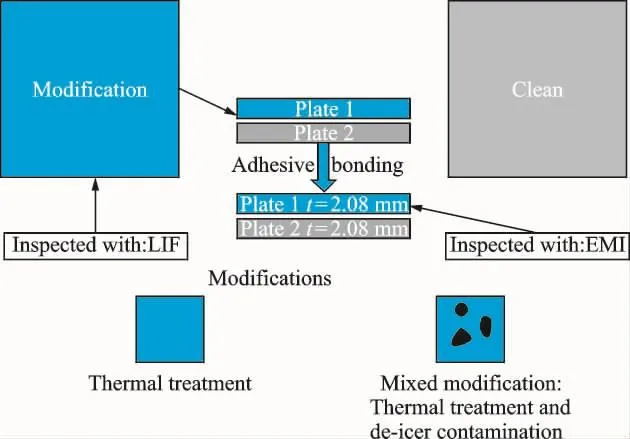
Fig.1 Overall concept of the pre-and post-bond inspection of the CFRP samples
The samples under investigation were made of Hexcel M21E/IMA material.The samples for surface assessment with LIF were single plates made of 8plies and layup sequence:[0,0,45,-45]S.Their size was 200mm×200mm.The samples for adhesive bonds assessment comprised of two plates with the same layup sequence adhesively bonded together.The bonded sample size was 100mm×100mm.The plates were bonded with FM 300-2adhesive cured at 121 ℃.The frame of the study is presented in Fig.1.Total 30 samples were investigated.Twelve samples for surface assessment comprised of three reference samples(RREx)and nine thermally treated samples.The thermally treated samples were hold in air circulation oven for 2h.Three levels of thermal treatment were investigated.Three samples were treated at 220℃ (RTD1x),three at 260℃(RTD2x)and three at 280 ℃ (RTD3x).This case simulated real situation that structural parts may be exposed to external heat source or lightening impact.High temperatures can cause local overheating and damage the resin.It leads to a loss of the mechanical properties of the CFRP structure and bonded repair can also be affected.Next,six samples were prepared with mixed modifications.It means that after thermal treatment(at 220 ℃)the samples were contaminated with deicing fluid.The contamination case with de-icer(DI)was prepared by dip coating of the plates in a water solution of the de-icer with two concentrations.The SAFEWAY KF de-icer was used.After dip coating the samples were dried in the oven for 2hat 40 ℃.Acclimatization at room temperature was allowed for at least 24h.The dip coating results were controlled by XPS measurements and potassium content was taken as an indicator of the contamination level[11].The sample with symbol RTD1DI1xhad the contamination on the level of 6.4at.%K,while the samples RTD1DI2xcontamination was 10.9at.%K.The used de-icer was a runway de-icing fluid that can affect the aircraft parts.After drying,the potassium formate,which was present in the de-icing fluid,formed a thin layer on the CFRP.When cleaning the aircraft before a repair,this fluid can be transported to bonding areas and contaminate the bond.This may lead to a weak adhesive bond.
The same scheme of treatment and contamination was followed for adhesively bonded samples.The bonded reference samples comprised of two plates without any thermal treatment.The modified bonded samples comprised of one plate after modification (only thermal treatment or thermal treatment with contamination)and one without any treatment.
1.2 LIF method
In-situ examination of large surface materials,like fibre reinforced composites,need special methods.The analytical methods should be nondestructive,enabling large surface analysis in relatively short time.LIF is a reasonable choice.This technique allows to analyze large objects using surface scanning technique.LIF is a technique based on the analysis of spontaneous emission of atoms or molecules excited with laser,where analyzed material can be in a gas,liquid or solid state phase.Typical instrumentation for LIF analysis consists of laser illuminating investigated material and the detection system for recording fluorescence.Depending of the chemical composition of analyzed material,laser can be tuned to match the wavelength to the absorption lines or bands of specified atoms or molecules and produce an electronically excited states that can radiate.
In this paper,LIF spectra were recorded using laboratory system.The samples excitation was provided by cw DPSS Nd:YAG laser operating at 532nm (Spectra Physics).Laser power was set to 0.2Wand laser intensity was 1W/cm2(5mm laser spot diameter).The spectra of the laser-induced fluorescence(LIF)were recorded in time integration mode.The emission spectra were dispersed by the 0.3mspectrograph SR-303iequipped with gratings of 600and 150grooves/mm and coupled to the time-gated ICCD camera DH 740(Andor Tech).Spectra were acquired in the range of 300—800nm with resolutions of 0.3nm or 1.2nm.The measurement set-up is depicted in Fig.2,where green excitation light(532nm)is seen illuminating CFRP sample surface,and de-tector is above the sample.
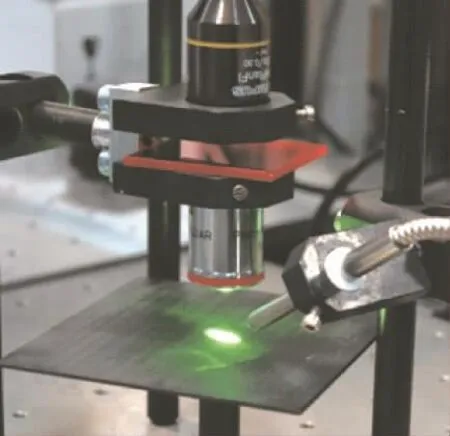
Fig.2 Laboratory equipment for measuring of LIF spectra
The presented work here follows the previous promising results[10].As it was shown the most effective excitation wavelength for thermal treatment assessment is 532nm and this is used here.At the surface of each sample,10measurements points are randomly chosen.Such measurement points selection allow for investigation of the variability of the intensity across the samples′surface.At each point,10spectra are gathered and the mean was calculated.
1.3 EMI method
The EMI method is considered as one of the NDT and SHM methods.The method principle is based on a piezoelectric sensor that is bonded to the inspected structure.During the measurement,electric quantities of the sensor are gathered for selected frequency band.The examples of investigated quantities are resistance,conductance,reactance or absolute value of the impedance.Due to direct and converse piezoelectric effect,the sensor excites the structure and senses the response from it.This electromechanical coupling causes the registered impedance spectra modification by the presence of the host structure.Various structural factors can influence the registered spectra. Appearance of additional resonance peaks,peak shift in frequency or magnitude change can be treated as indicators of defect of the structure.In order to extract damage related features for the EMI spectra,various frequency bands are analyzed.These bands depend on the inspected structure,the used piezoelectric sensor and the abilities of the available equipment.In this paper we focus on frequency band from 3—5 MHz.The band was selected as symmetric around the thickness resonance frequency of the used transducer.In the present work admittance(Y)was investigated on a complex plane.The measurements were conducted by gluing a single piezoelectric sensor per sample at the middle of the sample surface.
The admittance characteristic on complex plane comprise ofG(conductance)on the horizontal axis(real)and theB(susceptance)on the vertical axis(imaginary).The proposed comparison index is based on Frechet distance(FD).FD is the minimum distance required to connect two points constrained on two separate paths,as the points travel without back-tracking along their respective curves from one endpoint to the other[7].The definition is symmetric with respect to the two curves.The promising results of using FD to assessment of adhesive bonds contaminated with release agent was presented in Ref.[13].
2 Results
2.1 Observations using LIF method
The results for thermally treated samples assessed with LIF method are presented in Fig.3.There are high intensity values for the first level(RTD1x)of treatment.This case corresponds to keeping the samples at 220 ℃ in an oven.The samples TD2xand TD3xwere treated at higher temperatures and there is no correlation of the intensity with the used temperature.Moreover,the response is very uniform.All the six samples have comparable level of mean intensity and the standard deviation is low.
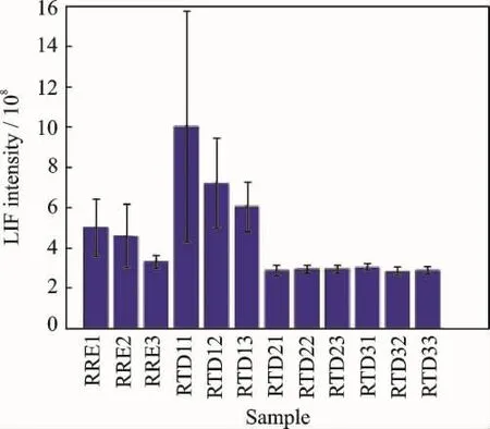
Fig.3 LIF method results for thermal treatment(RTD)
In Ref.[10]we saw a good detection of TD scenario with the LIF intensity measurement at 532nm excitation.Different levels of thermal treatment correlated with the intensity.The in-tensity value was growing with the growing temperature of treatment.Here we can see different behaviour.The first important difference is that the new samples (RTD)are made of different prepregs.Moreover the RTD samples were ground down to the fibres.The samples previously investigated were measured just after the thermal treatment without any surface modification afterwards(grindng,etc.)[10].The third important difference is that the RTD samples were treated at higher temperatures than before,while the other side of the sample was not prepared/modified in any way,so we can expect only influence of the temperature of the treatment.It was decided to measure this second side and compare the results with the previously obtained(Fig.3).The new result is presented in Fig.4.Again the highest intensity is observed for RTD1xsamples.The RTD2xand RTD3xsamples have intensity values on the level of reference samples.There is also a clear difference in vertical scale between Fig.3and Fig.4.This must be related to the considerable time interval between these two measurements.Recalling the previously published results[10],there was a clear intensity increase up to 210 ℃,while in this study,an increase is also observed but for 220 ℃.It seems that for 260 ℃ and 280℃,fluorescence is not observed in the considered bandwidth.
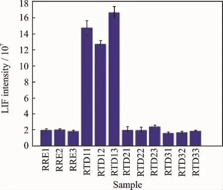
Fig.4 Results for thermal degradation (RTD)(fluorescence intensity measured on the back face)
Knowing that the 220℃case can be detected and distinguished for the remaining cases,anoth-er set of samples was prepared treated at the same temperature and contaminated afterwards with the de-icing fluid.Fig.5presents the results for new set of samples with mixed modification(RTD1DIxy)in comparison with the clean reference samples (RREx)and samples only after thermal treatment(RTD1x).The first observation is that the mixed modification was detected.It clearly differ from the reference.The higher level of de-icer(DI2)contamination is not related to any increase or decrease in relation to the lower level(DI1).What we can observe is that the intensities for the samples with mixed modification have higher values that for the pure thermal treatment(RTD1x). However,considering the standard deviations,all the results after modifications (RTD1xand RTD1DIxy)lie within the boundaries of standard deviation for the RTD11 case.
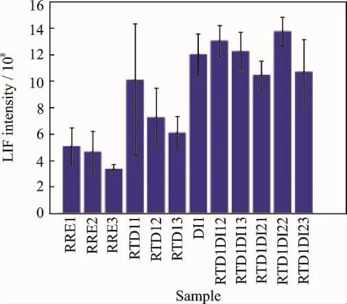
Fig.5 LIF results for mixed modifications of the surface compared with the thermal treatment at first level and referential results
2.2 Observations using EMI method
The results of calculating the FD value is depicted in Fig.6in a matrix form.It is symmetrical along the diagonal.Not all the results for measured samples are depicted here.After inspecting the spectra of free sensors and spectra obtained for the investigated samples,it was observed that for some samples the spectra look different.In some cases,the conductance maximum at about 4 MHz was not apparent or the peak magnitude increased after the sensor bonding to the sample.Total four such cases were identified and they were not analysed to avoid misinterpretation of the results,because the observed anomalies could be related to improper bonding of the piezoelectric sensors.Following samples were not considered further:RRE2,RTD12,RTD22,and RTD33.The main observation from the obtained matrix(Fig.6)is that there is a clearer difference between the two samples,RTD31and RTD32,and the rest of the samples.These two samples were treated with the highest temperature (280 ℃).The differences between the remaining part of the samples are not so evident.The exception is the RTD11sample.In order to visualize the obtained results,a clearer slice of the matrix plot was presented in Fig.7.It prese-nts the results in relation to RRE1sample.Small difference between reference samples is visible and the largest values of FD are observed for RTD31and RTD32samples.The difference between RTD31and RTD32samples could be caused by the difference of the samples and other factors.As it was shown before the RTD31sample has a delamination in one of the plates[11].
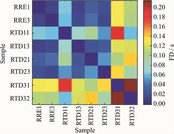
Fig.6 FD calculated for the reference and thermally treated samples in 3-5MHz bandwidth
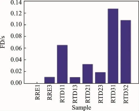
Fig.7 FD calculated for all samples in relation to RRE1 sample
The same analysis procedure as above was presented for samples with mixed modifications(RTD1Dixy).The result is plotted in Fig.8.The RTD1xsamples were plotted as well,for comparison.There is a significant high value observed for one of the samples with the highest level of modification(RTD1DI21).This is even more visible in the slice plot presented in Fig.9.Most of the samples with mixed modifications (except RTD1DI11and RTD1DI12)have higher FD values than the reference samples and the RTD1x samples.
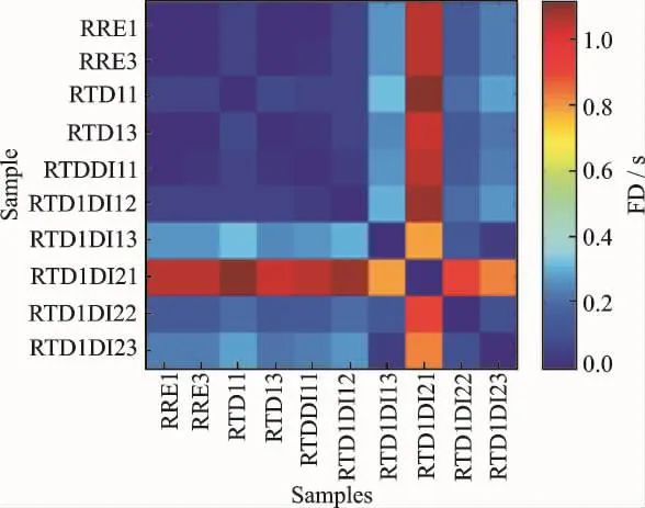
Fig.8 FD calculated for the reference and thermally treated samples at first level with mixed modification(3-5MHz bandwidth)
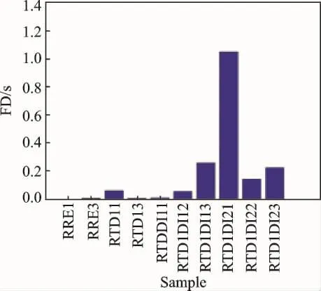
Fig.9 FD calculated for RTD1xand RTD1Dixy samples in relation to RRE1sample
3 Conclusions
The samples thermally treated at 220 ℃(RTD1x)are characterized with high level of LIF intensity in comparison to reference samples and samples treated at 260 ℃ and 280 ℃.The higher intensity values were observed for measurement on both sides of the samples.Above 220 ℃,the LIF intensity presented results comparable to reference samples.The thermal treatment level could not be determined for the considered cases.Taking into account the results presented in this paper and those in Ref.[10]it can be concluded that thermal degradation up to 220℃ can be distinguished.Moreover,it was shown that the detection of 220 ℃ was possible even if the surface was contaminated afterwards with the de-icing fluid.
Assessment of the bonded samples with EMI allowed clear separation of the samples treated at the highest considered temperature(280 ℃)and most of the samples with mixed modifications comprised of thermal treatment and de-icer contamination.
The research will be continued with different types of pre-bond surface modifications.
Acknowledgements
This project was supported by the European Union′s Horizon 2020Research and Innovation Program (No.636494).Authors would like to thank teams from:University of Patras,Fraunhofer IFAM,Aernnova,Airbus for preparing and characterization of the samples used in this research.
[1] VITO S D,MIGLIETTA M L,MASSERA E,et al.Electronic noses for composites surface contamination detection in aerospace industry [J].Sensors,2017,17(4):754.
[2] MALINOWSKI P, WANDOWSKI T, OSTACHOWICZ W.The use of electromechanical impedance conductance signatures for detection of weak adhesive bonds of carbon fibre-reinforced polymer[J].Structural Health Monitoring,2015,14(4):332-344.
[3] ECAULT R,TOUCHARD F,BOUSTIE M,et al.Numerical modeling of laser-induced shock experiments for the development of the adhesion test for bonded composite materials [J].Composite Structures,2016,152:382-394.
[4] MARKATOS D N,TSERPES K I,RAU E,et al.Degradation of mode-I fracture toughness of CFRP bonded joints due to moisture and release agent and moisture pre-bond contamination[J].Journal of Adhesion,2014,90:156-173.
[5] TSERPES K I,MARKATOS D N,BRUNE K,et al.A detailed experimental study of the effects of prebond contamination with a hydraulic fluid,thermal degradation,and poor curing on fracture toughness of composite-bonded joints[J].Journal of Adhesion Science and Technology,2014,28(18):1865-1880.
[6] MOUTSOMPEGKA E,TSERPES K I,POLYDOROPOULOU P,et al.Experimental study of the effect of pre-bond contamination with de-icing fluid and ageing on the fracture toughness of composite bonded joints[J].Fatigue & Fracture of Engineering Materials &Structures,2017,40(10):1581-1591.
[7] MARKATOS D N,TSERPES K I,RAU E,et al.The effects of manufacturing-induced and in-service related bonding quality reduction on the mode-I fracture toughness of composite bonded joints for aeronautical use [J].Composites:Part B,2013,45:556-564.
[8] LUDEKER W,GUNTHER K P,DAHN H G.Comparison of different detection set-ups for laser induced fluorescence monitoring of vegetation [C]∥EARSeL Advances in Remote Sensing[S.l]:[s.n.],3(3-VII),1995.
[9] WACHINGER G,MEER T,BEER S,et al.Detection of contaminants-A key aspect for composite adhesive repair bonding[C]∥ ECCM15-15th Europe-an Conference on Composite Materials.[S.l.]:[s.n.],2012.
[10]MALINOWSKI P H,SAWCZAK M,WANDOWSKI T,et al.Characterisation of CFRP surface contamination by laser induced fluorescence[C]∥Proceedings of SPIE.[S.l]:[s.n.],2014:90640E.
[11]MALINOWSKI P H, OSTACHOWICZ W M,BRUNE K,et al.Study of electromechanical impedance changes caused by modifications of CFRP adhesive bonds[J].Fatigue & Fracture of Engineering Materials &Structures,2017,40(10):1592-1600.
[12]EFRAT A,GUIBAS L J,HAR-PELED S,et al.New similarity measures between polylines with applications to morphing and polygon sweeping [J].Discrete and Computational Geometry,2002,28(4):535-569.
[13] MALINOWSKI P, WANDOWSKI T, OSTACHOWICZ W.Study on adhesive bonds influence on EMI signatures[C]∥Proceeding of 10th International Workshop on Structural Health Monitoring.[S.l]:[s.n.],2015:213-220.
杂志排行
Transactions of Nanjing University of Aeronautics and Astronautics的其它文章
- Simulation Tools for a Fiber-Optic Based Structural Health Monitoring System
- Segmentation of Thermographic Sequences in Frequency Modulated Thermal Wave Imaging for NDE of GFRP
- Non-destructive Evaluation of Absolute Stress in Steel Members Using Shear-Wave Spectroscopy
- Quantitative Rectangular Notch Detection of Laser-induced Lamb Waves in Aluminium Plates with Wavenumber Analysis
- Full Wavefield Analysis for Damage Assessment in Composite Materials
- Loading Localization by Small-Diameter Optical Fiber Sensors
