On the Use of Accurate Ignition and Combustion Models in Internal Ballistics Gun Codes
2018-05-17CliveWoodley
Clive Woodley
(QinetiQ, Fort Halstead, Sevenoaks, Kent TN14 7BP, United Kingdom)
Introduction
Emerging trends in high performance energetic materials are presenting significant challenges to the internal ballistics codes that are used to design charges used in guns. The challenges are three-fold. Firstly, higher energy propellants are being investigated to achieve higher projectile muzzle energy (either giving increased strike velocity for direct fire guns, or increased range for artillery). Secondly, low vulnerability ammunition (LOVA) propellants are being used to reduce the vulnerability of the munitions to attack from bullets, fragments and shaped charge jets. Thirdly, research into high loading density charge concepts, using conventional energy propellants, is being conducted to achieve higher projectile muzzle kinetic energy. High loading density charge concepts include consolidated/compacted propellant, travelling charges and novel propellant geometries. There is a pressing requirement for accurate, efficient and effective computational models that simulate the internal ballistics processes occurring in these charge concepts.
Another challenging charge is the modular charge system (MCS). The MCS comprises combustible cartridge cases, similar to cardboard but containing nitrocellulose, that present significant barriers to the combustion products from the primer and igniter. These barriers can withstand pressures as high as 50MPa before they ignite and burn or rupture, allowing the hot combustion products to reach the solid propellant inside. Modelling combustible cartridge cases represents particularly severe challenges to internal ballistics modelling. Under some circumstances, modules can move under the forces of the gas pressures.
In addition to that provided by the energetic component, there are significant challenges due to the geometry of the projectile or chamber. Much ammunition features projectiles that intrude significantly into the combustion chamber, such as cased telescoped ammunition (CTA). Other ammunition concepts feature bursting diaphragms, such as mortars where the main charge is contained in an aluminium tube within the tail unit of the bomb. The ignition and combustion of the propellant can create pressure waves that are due to the ignition process alone, and also can be due to the geometry.
The ignition and combustion processes can be simulated by using a multi-phase flow model in 1, 2 or 3 dimensions. Such a model comprises a set of partial differential equations expressing conservation of mass, momentum and energy for the gas and all solid phases. If there are different solid propellants then each propellant is modelled as a different phase. It is important that the computational domain and the numerical solution technique is robust, accurate and efficient in order to model any pressure waves and other internal ballistics processes.
A key part of the modelling is the development and application of models to improve the understanding of the ignition processes occurring in these advanced gun and charge concepts. When modelling the ignition of charges, it is important to model the complete ignition train, starting with the primer products from a vent tube or ignition cap. Ignition of the propellant can occur due to convection, conduction, radiation and condensation. Condensation and conduction are very important processes that are often neglected in internal ballistics models. Yet it is well known that black powder, the most commonly used igniter material, produces a high percentage of condensed combustion products.
A two-dimensional (2D) gun internal ballistics code named QIMIBS[1](QinetiQ Modular Internal Ballistics Software) has been developed to meet these challenges. Numerical techniques, based on Riemann solvers, are used to model accurately and efficiently any pressure waves that may be generated. QIMIBS contains models of the convective, radiative, condensative and conductive heat transfer processes from the igniter combustion products to the propellant. An intensive modelling work programme, closely supported by experiments to provide data for and to validate the modelling, has been undertaken for several different gun and charge concepts.
This paper describes the models and energy transfer equations important to the requirement to model the ignition of energetic materials for scenarios such as those described above. Included in the paper is an investigation of the internal ballistic processes caused by various internal geometrical features. Experiments and model validation is also described.
1 QIMIBS Model
The 2D unsteady reactive multi-phase flow equations for the gas phase are:
(1)
(2)

(3)

(4)
Equations (1), (2), (3) and (4) express the conservation of gas mass, conservation of gas momentum in the axial direction, conservation of gas momentum in the radial direction and the conservation of energy, respectively.

For each propellantk(k=1 ton, wherenis the number of propellants), the following conservation equations apply for the propellant mass, propellant momentum in the axial direction, propellant momentum in the radial direction and propellant particle number:
(5)

(6)

(7)
(8)
The volume fractions must sum to unity, i.e.
(9)
Finally, to close the set of equations, a co-volume (η) equation of state is used:
p(1/ρ-η)=RT/W
(10)
whereRis the gas constant,Tis the gas temperature andWis the molecular mass of the gas.
The equations are written in the following conservative form:
∂rQ+∂zF(Q)+∂rG(Q)=S(Q)
(11)
whereQare conserved variables,F(Q) andG(Q) are fluxes andS(Q) are source terms. Note that the set of partial differential equations is not hyperbolic. As a result, direct application of modern Godunov-type methods is not possible. However, the equations above are written in such a form that the homogeneous modified problem is hyperbolic, but the vector of the source terms includes spatial derivatives and constitute non-conservative terms of the equations.
Substantial effort has been devoted to the implementation of a propellant heating and ignition model. Details of this are reported elsewhere[1-2]- lack of space in this paper prevents a more detailed description. In summary, the unignited propellant is heated by the primer or igniter combustion products. Conductive, condensative, convective and radiative heat transfer processes are all modelled.
2 Numerical Method
The numerical algorithm consists of two major parts: i) a Cartesian Cut Cell (CCC) mesh generator; ii) a numerical scheme to solve the equations on the unstructured mesh produced by the mesh generator methods ensures accurate resolution of propagating waves such as shocks.
In the CCC approach to mesh generation[3-4]the domain of interest is cut out from the Cartesian mesh. Thus, away from boundaries, standard finite volume schemes can be used. Irregular (cut) cells near boundaries require special treatment. The implementation of the CCC mesh generator retains as much as possible of the original geometries without cutting corners′and allowing for cells that are split by solid boundaries. In this way, flow over very complex bodies can be computed.
A standard time-splitting procedure, consisting of two sub-steps, is used to advance the solution by one time step Δt. During the first sub-step, the homogeneous system obtained by neglecting the right-hand side of equations (1)-(9) is used to advance the solution by time step Δt. For this step the unsplit Godunov method is used:
(12)
whereVijis the size of the control volume (a computational cell),Nis the number of sides of the cell,Asis the length of the sides,Tsis the rotation matrix corresponding to sides,QLandQRare the vectors of cell averages either side of the cell edge, andFHLLCis a numerical flux.
During the second sub-step, the equations that result from neglecting the fluxes are solved. A standard Euler time discretization, where the vector of the source terms is evaluated at the low time level, is used.
(13)
When moving boundaries are present, an additional step must be done to account for body movement. During this step, the speed of all bodies is calculated according to the law of mechanics and the configuration is remeshed after the bodies have moved.
The conventional way to construct upwind fluxes is to use an approximate solution of the relevant local Riemann problem. However, the Riemann problem solution for the full system of equations is very difficult. A popular way to overcome this difficulty is to use the so-called phase splitting technique. Namely, the Riemann problem for the gas phase with frozen quantities of the solid phases is solved, the numerical flux is evaluated and the vector of the conservative variables is updated. Secondly, the Riemann problem for each of the solid phases is solved in turn, with the frozen gas pressure and again the vector of the conservative variablesUis updated. In this way, the first sub-step of the time-splitting procedure is split into three smaller sub-steps.
For each phase the HLLC (Harten-Lax-van Leer contact) Riemann solver[5-6]is used. This solver is an improvement over the well-known HLL Riemann solver in that it contains the middle (contact) wave in the Riemann problem solution. It does not use linearization of the equations and works well for low-density problems and sonic points without any fixes.
3 Applications of QIMIBS
QIMIBS has been extensively validated for a wide range of gun calibre and charge system. A typical example is for a 155mm indirect fire gun as shown in Figure 1. The charge system used comprises slotted tube triple base propellant ignited using a base-pad igniter. The red curve shows the measured data. The green curve shows the QIMIBS prediction when the ignition model is not used, i.e. the propellant ignites when the gas temperature exceeds the user-defined ignition temperature. The shape of the pressure profile is very similar to that measured. However, there is a substantial difference in the times at which the peak pressure occurs. The red curve shows the predicted pressure profile using the ignition model. There is very good agreement with the measured data both for the shape of the pressure profile and the time of peak pressure.
Fig.1 Comparison of QIMIBS with experiment for a 155mm cartridge
One of the first applications has been to model the internal ballistics of an 81mm mortar. The geometry for a typical primary cartridge is shown in Figure 2. Not shown in Figure 2 are various augmenting cartridges that could be present. The representation of the primary cartridge and mortar bomb simulated is shown in Figure 3. The dashed region, representing the fins, was not included in the specification of the geometry (because QIMIBS is a 2D code).
Fig.2 Primary cartridge (tail unit) of typical mortar bomb
Fig.3 Chamber and bomb profiles used in simulation
The internal ballistic processes occurring in such a launcher are very complicated. Firstly, the propellant in the primary cartridge is sealed within a thin aluminium tube. The black powder is ignited and the combustion products flow along the flash tube and into the aluminium tube. The propellant is ignited and begins to burn. However, no gas or propellant can flow out of the primary cartridge until the pressure in the aluminium tube exceeds a certain value. A typical burst pressure is on the order of 50MPa. After the aluminium tube ruptures, the hots gases and propellant rapidly flow out into the main mortar tube, igniting any augmenting charges that may be present. Figure 4 shows the predicted temperature distribution just after rupturing of the aluminium tube.

Fig.4 Predicted temperature distribution just after rupturing of the vent holes
The sudden venting of the primary cartridge causes the formation of shocks and pressure waves which interact with each other, the projectile body and the mortar tube wall. Figure 5 shows the predicted pressure profiles at various positions as indicated in the legend. The effect of the shock wave from the sudden venting process can clearly be seen by a jump in temperature at the breech face and, to a lesser extent, at the other locations nearby.
Fig.5 Predicted pressure profiles at various positions-coordinates are (distance from breech, radius)
MCS represent substantial challenges for the internal ballistician, from both an experimental viewpoint and a modelling viewpoint. A simplified MCS is shown in Figure 6. The combustible cartridge cases provide significant barriers to the propagation of combustion products from the primer and igniter. The primer might be offset from the axis of the central hole in the modules. Furthermore, the modules can act like projectiles if they are unlinked.

Fig.6 Typical modular 155mm charge system
QIMIBS has been used to model the ignition of an MCS for 5 modules in a ballistics simulator. Figure 7 shows the layout. Note that the vent tube at location (0,0.01) is offset from the central hole of the MCS to allow for the effect of the charge lying in the swiss groove of a gun such as the UK 155mm AS90. Figure 8 shows there is good agreement between the predicted and measured flamespread for two tests.
Fig.7 Representation of 5 module MCS in a ballistics simulator

Fig.8 Comparison and predicted and measured flamespread times
Simulations of gun firings of an experimental MCS were conducted to investigate the cause of abnormally high pressures. The predicted and measured pressure profiles are compared in Figure 9. For reasons of security, the data have been non-dimensionalised. The simulation revealed that the igniter design was faulty, leading to ignition occurring first at the projectile base. This led to severe pressure waves which are simulated very well as shown by the comparison of the pressure difference profiles.
Fig.9 Comparison of pressures
The last application of QIMIBS discussed in this paper is a simulation of a 140mm tank gun round. The geometry is shown in Figure 10. Figure 11 shows there is good agreement for the predicted breech pressure profiles using QIMIBS and IBHVG2 (a zero-dimensional code)[7].
Fig.10 140 mm Tank gun geometry
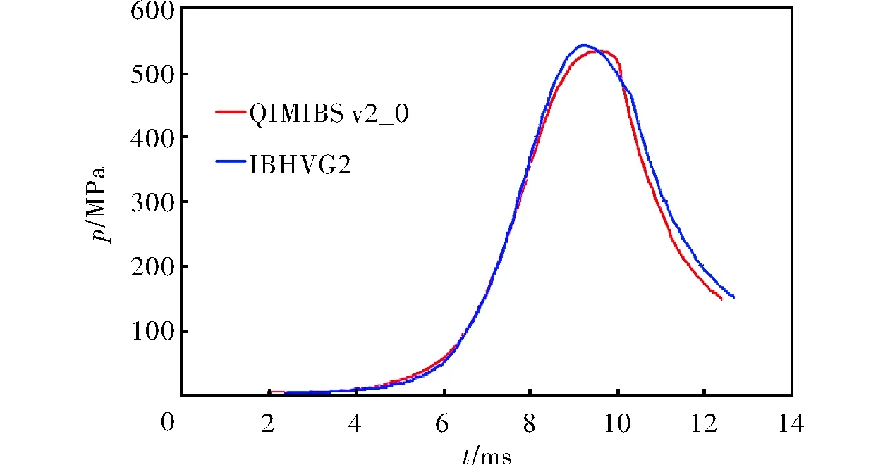
Fig.11 Comparison of predicted breech pressure profiles
4 Conclusions
(1) QIMIBS and, in particular, its detailed ignition models, has been validated for a wide range of different gun caliber and charge design. It has been used to investigate abnormal gun firings and has indicated the cause of the abnormality has been due to poor igniter design.
(2) QIMIBS provides a solid foundation for the assessment of advanced and novel charge designs for all types of gun, including cased telescoped ammunition, modular charges, tank gun rounds with substantial projectile intrusion and mortars. This will allow substantial savings in time and cost for future development projects.
References:
[1] Clive Woodley. Modelling the effects of non-gaseous igniter combustion products on the ignition of gun propellants[C]∥Proceedings of the 26th International Symposium on Ballistics. Miami:National Defense Industrial Association, 2011.
[2] Clive Woodley, Claridge R, Johnson N and Jones A. Ignition and combustion of pyrotechnics at low pressure and at temperature extremes[J].Defence Technology,2017,13(3):119-126.
[3] M J Aftosmis.Solution-adaptive cartesian grid methods for aerodynamic flows with complex geometries[R].USAF/NA SA Ames Research Center: von Karman Institute for Fluid Dynamics,1997.
[4] Berger M J & Aftosmis M J. Aspects (and aspect ratios) of cartesian mesh methods[C]∥Proceedings of the 16th International Conference on Numerical Methods in Fluid Dynamics.New York:NASA Ames Research Center Moffett Field,1998.
[5] Toro E F, Spruce M, Speares W. Restoration of the contact surface in the harten-lax-van leer riemann solver[J].Journal of Shock Waves, 1994,4:25-34.
[6] Toro E F.Riemann Solvers and Numerical Methods for Fluid Dynamics[M]. Second Edition.[S.l.]:Springer-Verlag, 1999.
[7] Anderson R D,Fickie K D. IBHVG2-A User′s Guide, Report BRL-TR-2829[R].[S.l.]:US Army Ballistics Research Laboratory, 1987.