Approximate solutions of the Alekseevskii–Tate model of long-rod penetration
2018-04-18JiaoChen
W.J.Jiao·X.W.Chen
1 Introduction
A number of studies[1–5]have been done for long-rod penetration into semi-infinite targets,as long rods made by high-density metal have taken the place of short steel rods as the penetrator against tank armor since the 1960s.Unlike the rigid projectile penetration,high density metal rods deform and erode intensely during their penetration at velocities in the range of 1.5–3 km/s.The first theoretical model was performed by Allen and Rogers[1],who performed several experiments on the impact of long rods made with different materials on aluminum targets by employing a two-stage light gas gun.A semi-hydrodynamic penetration theory,which assumes that the rod is rigid,except for a thin fluid region near the target–projectile interface where erosion is occurring,was formulated independently and almost simultaneously by Alekseevskii[2]and Tate[3,4].Their theory has been widely used in the analysis and predictions of long-rod penetration.
According to these models,the long-rod penetration process can be divided into four phases[5]:transient,primary,secondary,and recovery.The most important of these,the primary phase,is the kernel of most algebraic analysis and numerical simulations.The Alekseevskii–Tate model is suitable for this phase.The primary phase contains a quasi-steady hypothesis,which assumes that the pressure on the target-projectile interface,and the penetration velocity hardly change with time while both the projectile and target materials act as a fluid because of the high pressure on the interface.Therefore,the modified Bernoulli equation is employed to establish the relation between penetration velocity and impact velocity.Allen and Rogers’s equation[1]only considered the target strength,while the Alekseevskii–Tate model took into account the strengths of both the projectile and target.
The validity of the Alekseevskii–Tate model has been proved by numerous experiments and simulations,whilst also revealing its limitations.The major cause is that the 1D model did not take into account the 2D or 3D effects such as geometry effect,L/D effect,and oblique penetration.The discrepancy between the model and experimental data was presented by Hohler and Stilp’s[6]experiments of long tungsten alloy rods penetrating armor steel targets,and it showed the dependence of the normalized penetration(P/L)on L/D.This so-called L/D effect was further explored by Rosenberg and Dekel[7]and Anderson et al.[8],who employed axially symmetric 2D simulations.In their study,Anderson and Walker[9,10]used the 2D cylindrically symmetric option of CTH1CTH:a software system under development at Sandia National Laboratories Albuquerque to model multidimensional,multi-material,large deformation,strong shock wave physics.in their numerical simulations to get a better agreement with the experiment data,and they further discussed the discrepancy between the model and numerical simulations on this base.
Attempts to modify and revise the Alekseevskii–Tate model have been made by later researchers,and several theoretical models have been developed[9–12].A time dependent model based on an axial momentum balance equation and cylindrical cavity expansion solution was established by Anderson and Walker[9,10],by using the assumptions of the velocity and stress profiles in the projectile and the target from insights provided by numerical simulations.Although their model resulted in a better agreement with experimental results,it was achieved with the cost of much higher complexity,relying on several parameters and even on computer simulations[13].
Even with the stated limitations,the Alekseevskii–Tate model has been proven to be the most useful guide for longrod penetration studies.Typically,these equations are solved by integrating directly from the theoretical solutions given by Tate[3,4]or by using the exact solution developed by Walters and Segletes[14,15].However,due to the nonlinear nature of the equations,the rod(tail)velocity,penetration velocity,rod length,and penetration depth must be obtained implicitly as a function of time,and thus a numerical integral was needed.To get the explicit expression of these variables,first-order and third-order perturbation solutions of normalized Alekseevskii–Tate equations were successively undertaken by Forrestal et al.[16]and Walters et al.[17],respectively.Forrestal et al.’s solution is only valid for weak targets impact,and the good agreement between the theoretical solution and their first-order perturbation solution can be obtained only in a relatively short duration.Walters et al.’s first-order and third-order perturbation solutions are applicable for strong targets,since they include both the strengths of the projectile and target.In their comparison between the exact and approximate solutions for a penetration case,the third-order perturbation solution showed better agreement with the exact solution of the Alekseevskii–Tate equations.Actually,these perturbation solutions are not applicable for engineering application,for their inaccurate penetration time and complex mathematical expressions of the third-order solution.
The purpose of the present work is to obtain the explicit approximate theoretical solutions of Alekseevskii–Tate equations,which can greatly simplify the theoretical analysis since numerical integral is avoided.On the other hand,the theoretical prediction based on these approximate algebraic solutions can bring us much more intuitive understandings of the physics of long-rod semi-hydrodynamic penetration,and will be a faster and easier guide for engineering application.
2 Alekseevskii–Tate model of long-rod penetration
The one-dimensional model of long-rod penetration given by Alekseevskii[2]and Tate[3]derives from hydrodynamic theory.Rod and target strength are included in the modified Bernoulli equations.This semifluid model assumes that the projectile is rigid,except for an infinitesimally thin region near the target-projectile interface where erosion is occurring in a fluid manner.The model also assumes a balanced stress and a consecutive velocity at the interface which means the penetration velocity equals to the nose velocity of projectile,and the deceleration of the rear of projectile is governed by the flow stress of projectile.The governing equations are given as follows


whereρpandρtare the densities of projectile and target materials,respectively.Ypis the dynamic flow stress of projectile material andRtis the penetration resistance of target.u,v,p,andl?stand for the penetration velocity(nose velocity),projectile velocity(tail velocity),depth of penetration,and residual rod length,respectively,which are all functions of the timet.
From Eq.(1),the penetration velocity can be written as
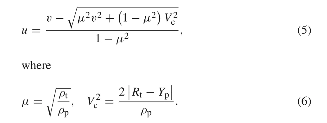
Vcstands for the critical tail velocity,and long-rod semihydrodynamic penetration initiates only ifv0>Vc.
Whent=0,we haveu=u0,v=v0,andl?=L;hereinu0,v0,andLare the initial penetration velocity(initial nose velocity),initial impact velocity(initial tail velocity),and the initial length of projectile.Using Eq.(5),if the initial tail velocityv0is known,the initial penetration velocityu0can be given by

IfRt>Yp,penetration ceases(u=0)when the projectile velocityvfalls below the critical valueVc,but the long rod still erodes while the target behaves as a rigid body,which is called interface defeat or dwelling.ForRt<Yp,the rod ceases to deform and proceeds to penetrate as a rigid body when the rod impact velocityvfalls to have a same value with the penetration velocity,u,i.e.,

Equation(2)can be transformed into the exact expression of Newton’s second law

wheremandSstand for the residual mass and the cross-section area of the long rod,respectively.Considering the eroded lengthlas the dominant variable in the analysis,whilel?+l=L,Eq.(3)can be transformed as

Therefore,term dv/dtin Eq.(2)can be transformed as

3 Theoretical solution(exact solution)of the Alekseevskii–Tate model
In this section,the governing Eqs.(1)–(4)will be solved to get the variation of pertinent variables(tail velocity,penetration velocity,depth of penetration,and residual length/mass of projectile)with the course of time.
As the relationship of penetration velocityuand tail velocityvhave been given by Eq.(5),while the eroded rod lengthland depth of penetrationphave been written as a function ofuandv,all we have to do is to find out the relationship betweenvandtby combining these equations.To this end,by substituting Eq.(11)into Eq.(9)and integrating,we obtain the relation oflandv.By replacing the hidden term in Eq.(9)with this relation,hence,the connection of tail velocityvandttime is finally found,and other variables are obtained correspondingly.
The geometry of an eroding cylindrical long rod is shown in Fig.1,in whichRis the rod radii,andLandlare initial length and eroded length of the rod,respectively.Mstands for the initial rod mass,and the cross-sectional area of the long rodSremains consistent as πR2during the penetration process.
Applying the geometry parameters and replacing the term dv/dtwith dv/dlin Eq.(11),Eq.(9)can be transformed as
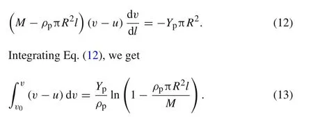

Fig.1 The geometry of eroding cylindrical long rod
Introducing the relative tail velocityv∗=v/v0and the relative critical tail velocityvc∗=v/v0,and substituting Eq.(5)into Eq.(13)and integrating,the relation between the eroded rod lengthland the relative tail velocityv∗can be obtained as

whereAandBare two newly defined dimensionless constants as

From Eq.(14),one can also obtain the relation between the residual rod massmand the relative tail velocityv∗
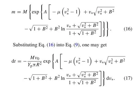
Defining a constant parameterC(dimension of[T])as

Integrating both sides of Eq.(17),changing of relative tail velocityv∗with timetis obtained
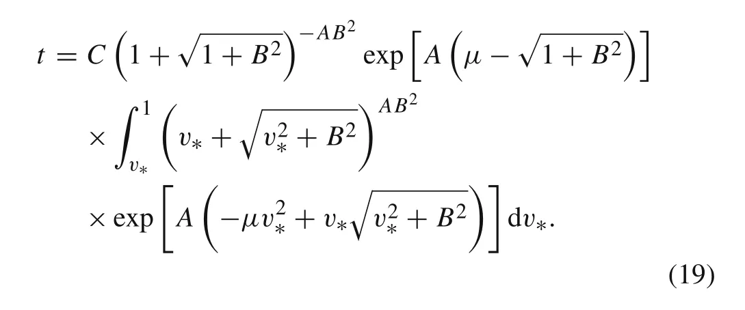
One cannot get the algebraic solution of Eq.(19)by integrating it,which means that the relative tail velocityv∗could not be formulated with the timetalgebraically.Alternatively,this problem can be solved numerically,using software such as MATLAB.In this way,v∗(v)could be calculated corresponding to a certain valuetof by Eq.(19).
Combined with Eq.(5),the penetration velocityuversus the timetis further obtained,and then the penetration depth can be obtained by applying Eq.(4).
Combining Eqs.(14)and(19),or using Eq.(10)to integrate former by means of the relationshipuandvwitht,the eroded rod lengthlversus the timetis obtained.
Similarly,the residual mass of rodmversus timetcan also be obtained.
Up to now,changes of the dominant variables with the course of time have been obtained.By applying Eqs.(4),(5),(14),(16),and(19),the theoretical(exact)solutions are fully obtained.However,as mentioned before,they are all implicit,so that the numerical integral with help of MATLAB and Mathematica should be needed to analyze their features.
CTH was used in Anderson and Walker’s[9]numerical simulation of long-rod penetration into semi-infinite steel target.The penetration(nose)velocity and impact(tail)velocity versus time derived from software was compared with that calculated from the Alekseevskii–Tate model.In addition,Walters et al.[17]employed the perturbation solutions to the Alekseevskii–Tate equations,giving the first-order and third-order approximate algebraic expressions of rod and penetration velocity,penetration depth,and rod length,which were compared with exact or numerical solution.Their analyses will be employed here to verify Eqs.(12)–(19).
The case shown in Anderson and Walker’s[9]work is for an L/D=10 tungsten alloy long rod(L=8.17 cm)impacting a 4340 steel target at an initial impact velocity of1.5 km/s,and the corresponding rod/target material parameters are:ρp=17.4 cm,Yp=2.0 GPa,ρt=7.8 g/cm3,Rt=4.94 GPa.Walters et al.[17]analyzed the test of the US Army Research Laboratory,namely a heavy metal,long rod(made of tungsten alloy or depleted uranium)penetrating a semi-infinite armor steel target,and their corresponding parameters are listed as follows:v0= 1.5 km/s,L=50 cm,ρp=17.6 cm,Yp=1.0 GPa,ρt=7.8 g/cm3,Rt=5.5 GPa.The listed parameters are enough for calculation and analysis of both cases.
Applying Eqs.(5)and(19),combined with corresponding parameters,one can get the variations ofuandvversus timet.The calculation results are compared with the velocity–time curves in Refs.[9,17],as shown in Figs.2 and 3.
As can be seen in these two figures,results calculated from these equations exactly correspond with those in Refs.[9,17],which means their velocity–time curves are in excellent agreement.Thus,for semi-hydrodynamic penetration of a cylindrical long rod,validity of Eqs.(12)–(19)is proven.
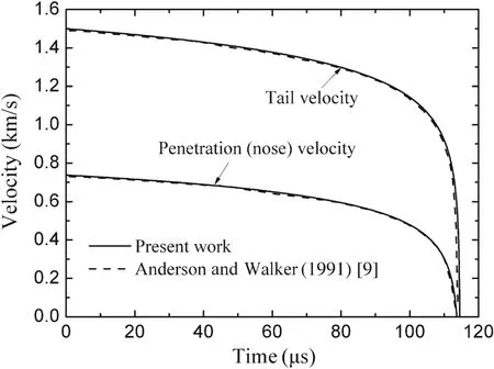
Fig.2 Penetration(nose)and tail velocity versus time for a tungstenalloy rod penetrating an armor steel target at an initial impact velocity of 1.5 km/s
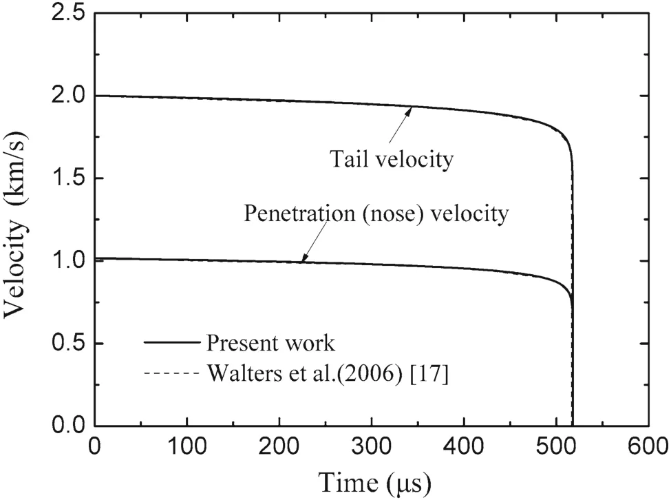
Fig.3 Penetration(nose)and tail velocity versus time for a tungsten rod impacting a steel target at an initial impact velocity of 2 km/s
4 Approximation of the theoretical solution
Notice that the exponent term in Eq.(14)is the function of the relative tail velocityv∗,and it is defined asy(v∗)

Considering the definition ofy(v∗),Eq.(14)can be transformed as

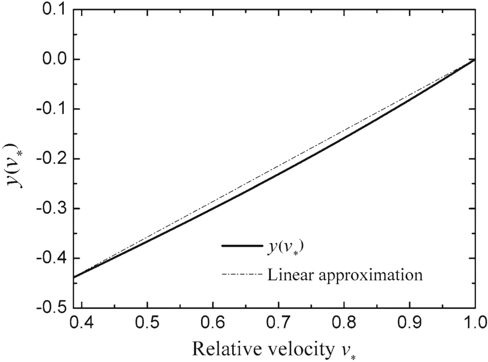
Fig.4 Function of the exponent term y(v∗)using parameters in Ref.[9]

Fig.5 Function of the exponent term y(v∗)using parameters in Ref.[17]
in whichAis a dimensionless constant;therefore,y(v∗)is exactly the logarithm of the relative rod length.Conservatively,it is the nonlinearity ofy(v∗)that lead to no algebraic solution of Eq.(19).Thus,simplification is taken into account.
Applying the corresponding parameters in Refs.[9,17],the profiles ofy(v∗)are shown in Figs.4 and 5.Under different combinations of projectiles and targets,the pictures indicate the weak nonlinearity ofy(v∗)withv∗in the available region of[vc∗,1].Spontaneously,a linear function ˜y(v∗)=K(v∗−1)is chosen to approximately substitutey(v∗).Kis defined as a dimensionless linear parameter,whose algebraic expression will be given by later analysis in this paper.
Substitutingy(v∗)with˜y(v∗),Eq.(17)can be integrated as

Especially,the terminal time of long-rod penetration can be expressed as

Dimensional analysis is employed for the cases in Refs.[9,17],and we haveμ≈ 2/3,A∈(10,40),vc∗,K∼ 2/3.Thus,exp[A K(vc∗−1)]∼ 0.01,which means the exponent term in Eq.(22)is much less than 1.Therefore,the terminal time of long-rod penetration can be approximately expressed as


(1)Approximate solution 1
From Eq.(21),the tail velocityvcan be expressed as an explicit function of timet

Substituting Eq.(24)into Eq.(5),one may obtain the explicit expression of the penetration velocityuwith timetas following

Explicit as it is,however,its form is not brief enough,and more simplification is needed.Back to Eq.(5),it can be rewritten as


Considering that the penetration velocity decelerates slowly when the penetration process is in the primary phase and far from the penetration stop,further approximation is made by neglecting the change of the second term of above equation and replacing it with a constant.This constant is chosen to


Although this step is not somehow mathematically rigorous,the linear relation between the penetration velocity and the tail velocity has been observed by a number of experiments and researches[18].Thus,the approximation of Eq.(28)is actually acceptable.
Substituting Eq.(24)into Eq.(28),the simpler explicit formula of the penetration velocityuwith timetbecomes

Integrating Eq.(10)and combining Eqs.(24)and(29),the eroded rod lengthlas a function of timetis obtained as

Similarly,the residual massmof the rod versus timetis obtained as

From the integration in Eq.(4)with combining Eq.(29),the penetration depthpversus timetis given by

By now,the explicit approximate expressions of the tail velocity,penetration velocity,eroded rod length,residual mass of the rod,and penetration depth are all obtained,and the complete algebraic solutions are gotten by employing Eqs.(24),(29),(30),(31),and(32),respectively.
(2)Approximate solution 2
In our former work,a linear approximation to the logarithmic relative rod length was applied,and the tail velocity as an explicit function of time was obtained by integrating Eq.(17).Approximation was also made to get the formula of the penetration velocity with time,and finally,combined with the governing equations,the explicit equations of the eroded rod length,the residual mass of the rod,and the penetration depth are obtained.The intent of the following work is to get a new approximate solution by switching another track.
Directly replacing the exponent termy(v∗)by the linear approximate function˜y(v∗)in Eqs.(14)and(16)and then substituting into Eq.(21),one can obtain the briefer explicit expressions of the eroded rod lengthland the residual massmof rod with timetas the following

Subtracting Eq.(32)from Eq.(30)and substituting Eq.(33),the penetration depthpas a function of timetcan be expressed as

By using Eq.(4)to differentiate Eq.(35),the penetration velocityuis obtained conversely as

From Eq.(10),i.e.,dl/dt=v−u,combined with Eq.(36),the tail velocityvis also obtained as

Obviously,the above two equations give us the constant penetration velocity and tail velocity,which implies they are independent with time.Comparing Fig.2 with Fig.3,one can observe that the case in Ref.[17]is much closer to the constant velocity state than that in Ref.[9].Whether it is connected to the material parameters of combinations of rod and target or the initial impact velocity will be analyzed later.
Using Eqs.(33)–(37),we obtained another set of explicit approximate algebraic solutions about the dominant variables in the long-rod penetration.To distinguish from the former approximate solutions,the set of solutions derived from Eqs.(24),(29),(30),(31),and(32)is named approximate solution 1,whilst the set of solutions derived from Eqs.(33)–(37)is named approximate solution 2.It is obvious that approximate solution 2 has a simpler formula,especially for its constant tail velocity and penetration velocity.However,it is not suitable for all cases in the long-rod penetration.Thus,we will especially discuss their differences and scopes of application in the next section.
(3)Solving of the dimensionless linear parameterK
Up to now,the value of dimensionless linear parameterKis still unknown and should be solved immediately.


The value of dimensionless linear parameterKis needed in Eq.(23)for the calculation of the terminal time of longrod penetration.Therefore,the validity of the expressions forKand Eq.(23)can be verified by comparing the calculated terminal time with the theoretical terminal time.As can be seen from Fig.2 and Fig.3,the values of theoretical terminal time in the cases in Refs.[9,17]are 113 and 518μs,respectively.Bringing in the corresponding parameters in these cases,the values ofKare calculated as 0.77 and 0.81,respectively,and the terminal time can be calculated as 116 and 517μs,respectively.Excellent agreements are obtained between the calculated and theoretical value of terminal time in both cases.Thus,the validity of Eqs.(23)and(38)are verified.
Hence,we get the full of approximate solutions after the certain figure ofKis solved.It is worth mentioning that,due to the definition ofK,the values calculated from Eqs.(30)and(33)are the same att=0 and also att=T.It is also true for Eqs.(31)and(34),(32)and(35),respectively.That is to say,approximate solutions 1 and 2 have the same the eroded rod length,residual mass of the rod,and penetration depth at both initial and terminal time.
5 Further discussions on the approximate solutions
Based on the linear approximation to the logarithmic relative rod length,two sets of approximate algebraic solutions were obtained by applying different tracks.The purpose of the following study is to analyze further these two sets of approximate algebraic solutions to draw a few brief inferences and to discuss the difference between them and their application scopes.
(1)Tail velocity
Differentiating Eq.(24),the deceleration of the tail velocity is obtained as

As can be seen,the deceleration of the tail velocity varies during the penetration process.It is smaller at the beginning,while becoming infinitely large when the penetration is close to the terminal time.Therefore,the tail velocity drops extremely near the penetration stop,corresponding to the steep falling edge at the curve of tail velocity versus time.
Comparing Eq.(24)with Eq.(37),the difference between approximate solution 1 and 2 can be regard as the difference between the logarithmic-varying tail velocity and the steady tail velocity.If the deceleration is relatively higher,the constant tail velocity is far from the truth.For other variables are deduced from the combination of the relationship of tail

Substituting Eq.(23)into Eq.(39),the initial deceleration of tail velocity is given by(it can also be deduced from Eq.(2))

From the above equation,the initial deceleration is independent of initial impact velocity.Instead,it is dependent on the dynamic flow stress,density,and initial length of the rod.Comparing the cases in Refs.[17]and[9],one can easily find that the initial deceleration in the former case is only 8%of that in latter one.While their target densities are much the same,however,the former rod has a smaller flow stress(only a half of the latter)and a longer initial rod length(as six times of the latter),which causes the tail velocity in Fig.3 to be much closer to steady than that in Fig.2.
(2)Penetration velocity
Differentiating Eq.(25),we have

which means the deceleration of penetration velocity has the same pattern with the deceleration of tail velocity.That is to say,the penetration velocity changes slowly at the beginning while it drops dramatically as the end draws near.Thus,there is a steep falling edge at the penetration velocity versus time curve as well.
From Eq.(29),the penetration velocity can be further deduced as

The penetration velocity is expressed in Eqs.(5)and(7),Eqs.(42)and(43),as well as Eq.(36),respectively.The comparative analysis is worth to be conducted.
The penetration velocity given by Eq.(5)is linked to the tail velocity,and they are deduced directly from the governing equations of the long-rod penetration.Therefore,the initial penetration velocity obtained by subtracting the initial tail velocity into Eq.(7)is an theoretical(exact)one.
The penetration velocity given by Eq.(42)is the function of time,so that its variation with time is fully described.However,there are several approximate assumptions during the simplification,for which the initial penetration velocityu0obtained by subtractingv0into Eq.(43)is an approximate one.
Different from the above two,the penetration velocity calculated from Eq.(36)is a constant.Because of the physical basis of the dimensionless linear parameterK,approximate solutions 1 and 2 have the same terminal penetration depth.That is to say,the time integrals of penetration velocity regarding these two solutions are the same.Thus,the constant velocity can be regarded as the average value of the penetration velocity.For the penetration velocity decelerates monotonously during the penetration process,this average penetration velocity is generally less thanu0.
Bringing in the corresponding parameters for the cases in Refs.[9,17],the values of these three penetration velocities are compared.Under the initial impact velocity of 1.5 km/s[9],the dimensionless initial penetration velocitiesu0/v0given by Eqs.(7)and(43)are 0.4916 and 0.4868,and that from Eq.(36)is 0.4216.For the initial impact velocity of 2 km/s,these three dimensionless velocities are 0.5079,0.5043,0.4867,respectively.To sum up,the initial penetration velocity calculated from approximate solution 1 approaches the exact theoretical solution,whilst approximate solution 2 gives a lower penetration velocity,and it is consistent with the result of this analysis.It is mentioned simultaneously that regarding the case in Ref.[17],the constant or average penetration velocity of approximate solution 2 is much closer to the initial value given by the theoretical solution and approximate solution 1.This illustrates that the case of Ref.[17]is more suitable for steady-velocity assumption.
(3)Application scopes for approximate solutions
The lowest permitted impact velocity can be easily obtained by judgingu0?0.
According to Eq.(7),the semi-hydrodynamic penetration starts with an initial impact velocityv0?Vcforu?0.Consequently,the lowest permitted impact velocity for the theoretical solution is the critical tail velocityVc.
Regarding approximate solution 1,substitutingu0=0


Bringing in the corresponding parameters of the cases,differences of the lowest permitted impact velocities calculated from different solutions are discussed in number.Corresponding to Anderson and Walker’s[9]case,the lowest permitted impact velocities given by approximate solutions 1 and 2 are 0.65 and 0.67 km/s,respectively,and they are both higher than the critical tail velocity of 0.58 km/s.For the case in Ref.[17],these three lowest permitted impact velocities are 0.80,0.83,0.72 km/s,respectively.Similarly,both approximate solutions 1 and 2 have higher critical tail velocity.

Hence,the application scope for approximate solution 1 isv0?vlow1.However,the validity of approximate solution 2 requires not only that the initial tail velocity(impact velocity)is higher than the critical value,i.e.,v0?vlow2,but also the steady velocity(tail and penetration)assumption is satisfied.
(4)Eroding rate The rates of eroded rod length in two sets of the approximate solutions are discussed respectively in this section.The interest of this manuscript is focused on the cylindrical long rod with a flat nose,and thus the cross-sectional area of the rod stays the same during the penetration process.As a result,the changes of rod length and mass have the same pattern.Therefore,the eroding rate is represented by the rate of eroded rod length.
Firstly,the eroding rate in approximate solution 1 can be deduced from Eq.(30)as

Obviously,the rate of eroded rod length decreases with the deceleration of tail velocity.According to the aforementioned discussion,if the rod is longer or its material is denser or softer,the tail velocity is closer to constant because the deceleration is relatively low.Therefore,the eroding rate is approaching a constant in that scenario.
Approximate solution 2 gives us a constant eroding rate as

For its brief form and clear physical significance,applying this equation can be much more convenient only if the validity of approximate solution 2 is guaranteed.
(5)Penetration efficiency
At the end of this section,the penetration efficiency,i.e.,the relationship between dimensionless penetration depth and the impact velocity,which is the mostly concerned issue in long-rod penetration,is analyzed further based on approximate solution 2.It is deduced from Eq.(33)and Eq.(35),


It should be mentioned in particular that,in Fig.6,the curve of dimensionless penetration depth does not start atv0=Vc,but starts at the lowest permitted impact velocitiesvlow2.For three cases of rod/target combinations ofYp=1.0 GPa andRt=5.0 GPa,Yp=2.0 GPa andRt=5.0 GPa,andYp=1.0 GPa andRt=3.0 GPa,the values ofvlow2are higher thanVcat 71%,74%,78%,respectively.Thus,using Eq.(47)at low velocity will cause deviation and further modification is required if we want to use it in quantitative analysis.
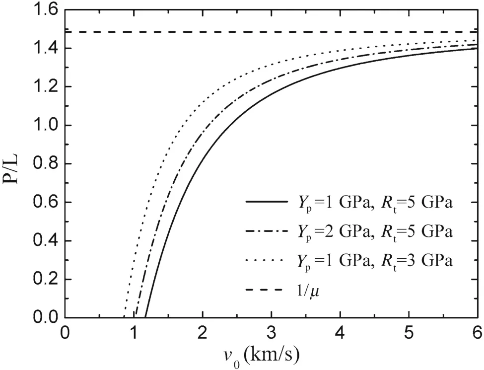
Fig.6 The dimensionless penetration depth versus the initial impact velocity for a tungsten alloy projectile penetrating a steel target
Qualitative understanding is obtained by observing Fig.6.Firstly,the penetration depth grows dramatically during the ordnance velocity scope(1.0–2.0 km/s)and approaches the hydrodynamic limit 1/μat higher velocity.In addition,the penetration depth heavily relies on the target strength in the case of relatively low impact velocity.For a tungsten alloy rod withYp=1.0 GPa penetrating steel target at an impact velocity of1.5 km/s,the penetration depth will decrease 50%if the target strength changes from 3.0 to 5.0 GPa.However,with increasing the impact velocity,e.g.,larger than 3.0 km/s,this deviation caused by the target strength will be distinctly decreased and tends to be ignored.It agrees with the prediction of the Alekseevskii–Tate model,i.e.,the influence ofRtwill gradually dis appear when the impact velocity increases.These features have also been observed by a lot of experiments with different rod/target combinations[6,19–22].
In the present analysis based on the Alekseevskii–Tate model,the rod strength will also affect the penetration depth,and it increases 46%at an impact velocity of 1.5 km/s whenYpchanges from 1.0 to 2.0 GPa whileRt=5.0 GPa.However,all the results of experiments and numerical simulations indicate that the effect of rod strength will be smaller.This is discussed by Rosenberg and Dekel[23]who blamed it on the high deceleration at the tail of the high-strength rod.The raise in penetration depth caused by the high strength of the rod material is weakened by the growing deceleration.

Moreover,as can be seen from Eq.(47),the penetration where the penetration efficiency drops dramatically with the increasing of the aspect ratio.
In conclusion,the features analyzed from Eq.(47)are supported by numbers of experiments and simulation results,so that the validity of the qualitative analysis is verified.However,the penetration depths predicted by the Alekseevskii-Tate model are lower than the experimental data and simulation results,which are all tend to cross the hydrodynamic limit.The Alekseevskii–Tate model can only reflect the primary phase of long-rod penetration.The extra penetration depth is mostly from the secondary phase and compressibility of projectile and target materials.Correla-tive discussions are made by Rosenberg and Dekel[13,23],Sternberg and Orphal[21],and Anderson et al.[24,25].
6 Comparison of the approximate solution and the first-order perturbation solution
In hypervelocity long-rod penetrationv2c∗,and 1/ΦJpare all tiny quantity because of the high initial impact velocity.Neglecting the minor term in Eq.(38),the dimensionless linear parameter is approximately transformed into


By revisiting the first-order perturbation solution,v0?vlow1is not competent to guarantee its validity.For a certain combination of rod and target,the initial impact velocity should be high enough to ensure the terms ofv2c∗and 1/ΦJpin Eq.(38)can be neglected.Consequently,it will result in a huge deviation when employing the first-order perturbation solution departs from these criteria,especially under a relatively low impact velocity.
To sum up,the first-order perturbation solution obtained from complex analysis and calculation by Walters et al.[17]is a special form of approximate solution 1.In contrast,the present analysis is simpler in math and clearer in physics,and simultaneously all the formulae are explicit and brief.Thus,apparently,they are more applicable in engineering.
7 Model parameters in the long-rod penetration
Based on the Alekseevskii–Tate model of long-rod penetration,the dominant parameters,which affect the variation of pertinent variables with time,include the material parameters of rod and target,geometrical parameters of the rod,and initial impact velocity.These parameters are expressed in approximate solutions in forms of the characteristic timeτ,the dimensionless density parametersμand¯μ,Johnson damage numberΦJp,the relative critical tail velocityvc∗,and the dimensionless linear parameterK.Because of the simplicity and explicitness of the approximate solutions,these parameters can be discussed in detail briefly to analyze their influence.
The characteristic timeτdepends on the initial rod lengthLand the initial impact velocityv0.Apparently,the characteristic timeτdecreases with the increasing of initial impact velocityv0and increases with the raising of the initial rod lengthL.Based on Eq.(23),the characteristic timeτdirectly affects the terminal timeT,i.e.,Tis proportional toτ.
μand¯μare two dimensionless density parameters corresponding to the density ratio of rod and target.Their larger,μis smaller while¯μis larger.Asμand¯μoccurring in all the formulae from Eq.(23)to Eq.(38),the variation of the pertinent variables all depend on these two parameters.In other words,the rod and target densities are important parameters in long-rod penetration.
ΦJpis a dimensionless parameter that represents the damage extent of structures.It is related to the initial tail velocityv0,the rod densityρp,and the dynamic flow stressYpof the rod.From Eqs.(39)–(41),Johnson damage numberΦJpwill directly affect the deceleration of the tail and nose of the rod.The deceleration is inversely proportional to the parameterΦJp.
The relative critical tail velocityvc∗is the ratio of the critical tail velocityVcand the initial tail velocityv0.Vcis relevant toρp,Yp,andRt,and it is higher if the strength difference between the rod and target is larger while the rod density is smaller.For a certain combination of rod and target,Vcis a given constant so thatvc∗is apparently inversely proportional tov0.According to Eqs.(42)and(43),the relative critical tail velocityvc∗controls the penetration velocityuby affecting the initial penetration velocityu0.For a given initial impact velocityv0,if the strength difference between rod and target is larger,vc∗will be higher and thusu0will be lower.
Given by Eq.(38),the dimensionless linear parameterKcontains not only all the material parameters,but also the initial impact velocity.Kdecreases with the raise ofv0and the ratio of rod and target density stands out among all the material parameters.Koccurs in all the relationship of the pertinent variables versus time.Especially,in approximate solution 2,the eroded rod length(mass)and the penetration depth are proportional toK.
Dimensional analysis of the above parameters is conducted in the cases of Refs.[9,17].The rod density in both cases has little difference,and so do the target density.Thus,μis equal to 0.67 and¯μis 0.84 in both cases.Moreover,ΦJpis 19.58 and 70.4,vc∗and is equal to 0.39 and 0.36,whileKis calculated as 0.77 and 0.81,respectively.
In addition,based on the analysis in the last section,the values ofΦJpandvc∗ directly determine the validity of the first-order perturbation solution given by Walters et al.[17].Comparing the parameters in two cases,ΦJpis larger whilevc∗ is lower in Ref.[17]’s case,and it leads to a more suitable condition for the first-order perturbation solution for their case.
From Eq.(48)K≈2(1−μ)is valid when the impact velocity is relatively high.Therefore,the dimensionless linear parameterKcan be assumed to depend on the density ratio of rod and target only,while it is independent of other parameters.Even if this assumption may cause a great deviation under a relatively low impact velocity,it can briefly reflect the variation pattern of various dominant variables in long-rod penetration,which make it acceptable in qualitative analysis.


An apparent conclusion can be drawn from this formula that the terminal time of quasi-steady-state of long-rod penetration is proportional to the initial rod length and inversely proportional to the initial impact velocity.Meanwhile,a higher density ratio of rod and target leads to a longer penetration time.
Regarding the two cases in Refs.[9,17],the characteristic timeτis54.5 and 250μs,respectively.However,the terminal timeTcalculated from Eq.(22)is 116 and 517μs(nearly double the characteristic time),respectively,which is very close to the theoretical prediction of the penetration time(113 and 518μs).Meanwhile,the terminal time calculated from Eq.(23)is 119 and 519μs,respectively,and it is still very close to the theoretical prediction of the penetration time.Differently,˜Testimated by Eq.(53)are 136 and 626 μs,respectively.
Regarding the deceleration of the rod tail,Eq.(39)can be simplified after substitutingKwith¯K=2(1−μ),


Finally,the discussion focuses on the eroding rate of the rod length.The eroding rate of the rod length in approximate solution 1 is less dependent.In approximate solution 2,K=2(1−μ),Eq.(45)can be transformed as

Obviously,the eroding rate dominantly depends on the density ratio of rod and target,and it is proportional to the initial impact velocity.In other words,the strength effect of rod and target is limited.
8 Example analyses
Combined with the corresponding parameters in Refs.[9,17],the approximate solutions and the first-order solutions are compared with the theoretical(exact)solutions.The curves of the dominant parameters versus time are drawn in following pictures.
The case of the tungsten alloy rod penetrating the armor steel target at the initial impact velocity of1.5 km/sin Ref.[9]is shown in Figs.7,9,and 11,respectively.Comparatively,the case ofv0=2.0 km/s in Ref.[9]is displayed in Figs.8,10,and 12,respectively.Figures 7 and 8 depict the curves of penetration and tail velocity versus time.Figures 9 and 10 describe the curves of residual rod length versus time.Figures 11 and 12 represent the curves of penetration depth versus time.In all these figures,approximate solutions 1 and 2,the first-order perturbation solution and the theoretical(exact)solution are marked by dot-dash line,dash line,dot line,and solid line,respectively.
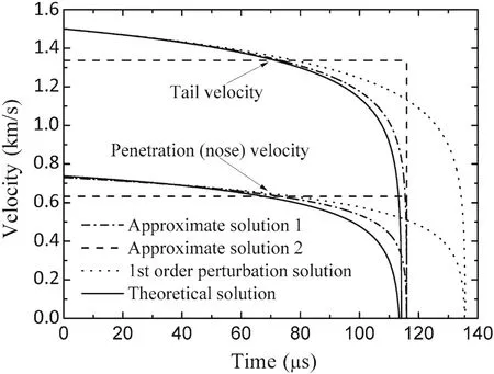
Fig.7 Penetration(nose)and tail velocity versus time for a tungsten alloy rod penetrating an armor steel target at an initial impact velocity of 1.5 km/s:comparison of different solutions
In the case ofv0=2.0 km/s,the theoretical penetration time is about 113μs while the penetration times given by the first-order perturbation solution and approximate solution 1 are 136 and 116μs,respectively.As can be observed from Fig.7,approximate solution 1 is much more close to the exact solution than the first-order perturbation solution in the penetration time,the tail velocity and the penetration velocity.In particular,at a time close to the end of the penetration process,say 100μs,the tail velocity deviates from the theoretical solution by 3.05%for approximate solution 1 and 9.06%for the first-order perturbation solution.Correspondingly,the deviations for the penetration velocity from the theoretical solution are 12.12%for approximate solution 1 and 20.71%for the perturbation solution.
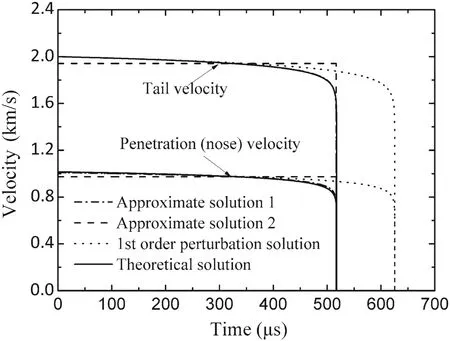
Fig.8 Penetration(nose)and tail velocity versus time for a tungsten rod impacting a steel target at an initial impact velocity of 2 km/s:comparison of different solutions
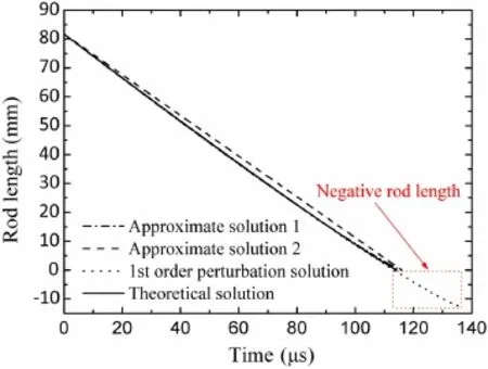
Fig.9 Residual rod length versus time in the case of 1.5 km/s:comparison of different solutions
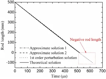
Fig.10 Residual rod length versus time in the case of 2 km/s:comparison of different solutions
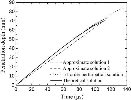
Fig.11 Penetration depth versus time in the case of 1.5 km/s:comparison of different solutions
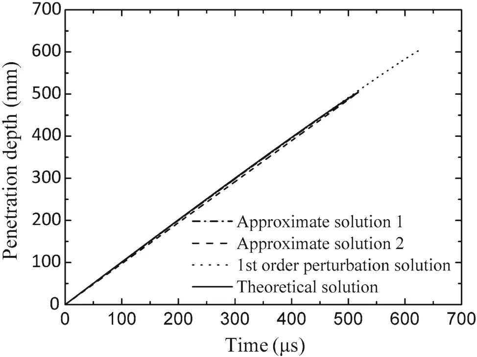
Fig.12 Penetration depth versus time in the case of 2 km/s:comparison of different solutions
Similarly,from Fig.8,in the case ofv0=2 km/s,approximate solution 1 is still much closer to the theoretical solution while the first-order perturbation solution shows a huge deviation in the penetration time,the tail velocity and the penetration velocity.The theoretical penetration time is nearly 518 μs,and its values calculated from approximate solution 1 and the first-order perturbation solution are517 and 626μs,respectively.Near the penetration stop,saying 500μs,the tail velocity deviates from the theoretical solution by 0.19%for approximate solution 1 and 5.07%for the first-order perturbation solution.The deviations for the penetration velocity from the theory are 1.63%for approximate solution 1 and 7.66%for the perturbation solution.
To sum up,for the tail and penetration velocity,the approximate solution 1 and the first-order perturbation solution are in excellent agreement with the theoretical solution,which makes it hard to distinguish them out.However,the deviation exists near the termination of penetration process,in which approximate solution 1 is closer to the exact prediction directly evaluated from the Alekseevskii–Tate model.
As shown in Figs.7 and 8,the penetration time is the same for approximate solutions 1 and 2.Moreover,combined with the integral meaning,the physical implications of the steady tail velocity and penetration velocity in approximate solution 2 are discovered as follows.
Basically,the time integral of penetration velocity,represented by the area between the curves of penetration velocities and the time axis in the figures,is actually the penetration depth.According to the definition of the dimensionless parameterK,approximate solutions 1 and 2 have the same penetration depth.Thus,the region enclosed with the lower dot-dash line and the time axis has the same area as the rectangle below the lower dash line.
From Eq.(10),the time integral of the difference between the tail velocity and the penetration velocity,represented by the area between the curves of the tail velocity and the penetration velocity,is actually the eroded rod length.Similarly,approximate solutions 1 and 2 have the same eroded rod length.Therefore,the region enclosed with two dot-dash lines and the rectangle enclosed with two dash lines are the same area.
According to the above integral meaning,the constant tail velocity and penetration velocity can be regarded as the average tail velocity and the average penetration velocity during the primary phase of the penetration process.
Figure 9 clearly depicts that the residual rod length given by approximate solution 1(calculated from Eq.(30))is closer to the theoretical(exact)prediction,while the value given by approximate solution 2(expressed by Eq.(33))changes linearly with time and equals that given by approximate solution 1 at the penetration stop.Figure 10 shows a similar phenomenon;all the curves are close to each other and only the first-order perturbation solution may be distinguished to deviate a lot from the theoretical solution at the terminal time.Regarding the case of 1.5 km/s,the deviations from the theoretical prediction of the final eroded rod length are 0.61%for approximate solution 1,0.51%for approximate solution 2,and 15.90%for the perturbation solution,respectively.In another case of 2.0 km/s,the final eroded rod length deviates from the theoretical solution by only 2.02×10⁻⁵and 1.68×10⁻⁵for approximate solutions 1 and 2,respectively,but 20.47%for the first-order perturbation solution.Especially,there exist negative residual rod lengths given by the perturbation solution,which is not true and thus Walters et al.[17]deleted the data after the theoretical penetration time.
As can be seen from Figs.11 and 12,penetration depths given by the approximate solution 1(calculated from Eq.(32))and the first-order perturbation solution are greatly close to the theoretical prediction,but the first-order perturbation solution gives out a higher final penetration depth.Comparatively,the linear penetration depth given by approximate solution 2(expressed by Eq.(35))approaches the theoretical solution at the final penetration depth.In Fig.11,deviations of approximate solutions 1 and 2 and the perturbation solution are 4.53%,4.34%,and 19.19%,respectively.In Fig.12,the deviations are 0.31%for approximate solutions 1 and 2,and 19.79%for the first-order perturbation solution,respectively.
With comparing Figs.7 and 8,9 and 10,11 and 12,respectively,one can draw a conclusion that approximate solutions 1 and 2,as well as the first-order perturbation solution all show a good agreement with the theoretical(exact)solution at early time of the penetration,while deviations occur at the later period.Regarding approximate solutions 1 and 2,the deviations for all the dominant variables are very small and can be ignored.But for the first-order perturbation solution,it predicts a longer penetration time and thus gives larger penetration depth and negative residual rod length.

The deviation between the theoretical solution and the approximate solution 1 is actually caused by the logarithm imate solution 1 is accurate and the deviation only occurs when the singularity is approached.As being explicit and simple,approximate solution 1 must be quite powerful in the long-rod penetration analysis.At the same time,approximate solution 2 may be employed to conduct the qualitative and quick analysis in the long-rod penetration.
9 Conclusion
The theoretical solution of the Alekseevskii–Tate model was deduced and the variations of dominant parameters versus time were obtained by former researchers.However,they are all implicit so that numerical calculation is needed to analyze them.Employing a linear approximation to the logarithmic relative rod length,two sets of approximate algebraic solution are obtained,which is explicit and simple in math.In particular,regarding approximate solution 1,the tail and penetration velocities vary logarithmically with time,and the eroded rod length,residual rod mass and penetration depth are deduced from their integrals.In approximate solution 2,the tail and penetration velocities are constant,and the other dominant parameters vary linearly with time.
Based on these solutions,the inferences about the tail and penetration velocities,eroding rate,and penetration efficiency have been drawn with clear physical meaning.Difference between two approximate solutions and their application scope are further discussed.The application scope for approximate solution 1 isv0?vlow1.Comparatively,approximate solution 2 requires not onlyv0?vlow2,but also the steady velocity(tail and penetration)assumption.
Meanwhile,neglecting the minor term of the dimensionless linear parameterKin the high-speed penetration,the first-order perturbation solution given by Walters et al.]can be fully deduced from approximate solution 1.Therein the perturbation solution is only a special form of approximate solution 1 and its validity is revisited.Moreover,dominant model parameters in long-rod penetration are generally discussed and some inferences are simplified on this base.The most important simplified inference is that the strength effect of rod and target is limited in high-speed penetration.
By means of the analysis of two cases,the differences of approximate solutions 1 and 2,the first-order perturbation solution and the theoretical(exact)solution are examined.Approximate solution 1 is closer to the theoretical prediction of the Alekseevskii–Tate model than the first-order perturbation solution,and it is strongly recommended in engineering application.Approximate solution 2 brings us much more intuitive understandings of long-rod penetration,which is convenient for the qualitative analysis.
It is worth noting that due to the limitation of the Alekseevskii–Tate model itself,the approximate solutions developed in this manuscript is valid only for the primary phase of long-rod penetration.Therefore,the deviation between the results of experiments and numerical simulations and the theoretical prediction based on our approximate solutions cannot be avoided,which should be taken into account in engineering application.
AcknowledgementsThe project was supported by the National Outstanding Young Scientist Foundation of China(Grant 11225213)and the Key Subject“Computational Solid Mechanics”of China Academy of Engineering Physics.
1.Allen,W.A.,Rogers,J.W.:Penetration of a rod into a semi-infinite target.J.Franklin Inst.272,275–284(1961)
2.Alekseevskii,V.P.:Penetration ofa rod into a target at high velocity.Combust.Explos.Shock Waves 2,63–66(1966)
3.Tate,A.:A theory for the deceleration of long rods after impact.J.Mech.Phys.Solids 15,387–399(1967)
4.Tate,A.:Further results in the theory of long rods penetration.J.Mech.Phys.Solids 17,141–150(1969)
5.Christman,D.R.,Gehring,J.W.:Analysis of high-velocity projectile penetration mechanics.J.Appl.Phys.37,1579–1587(1966)
6.Hohler,V.,Stilp,A.J.:Hypervelocity impact of rod projectiles with L/D from 1 to 32.Int.J.Impact Eng.5,323–331(1987)
7.Rosenberg,Z.,Dezel,E.:The relation between the penetration capability of long rods and their length to diameter ratio.Int.J.Impact Eng.15,125–129(1994)
8.Anderson,C.E.,Walker,J.D.,Bless,S.P.,et al.:On the L/D effect for long-rod penetrators.Int.J.Impact Eng.18,247–264(1996)
9.Anderson,C.E.,Walker,J.D.:An examination of long-rod penetration.Int.J.Impact Eng.11,481–501(1991)
10.Walker,J.D.,Anderson,C.E.:A time-dependent model for longrod penetration.Int.J.Impact Eng.16,19–48(1995)
11.Rosenberg,Z.,Marmor,E.,Mayseless,M.:On the hydrodynamic theory of long-rod penetration.Int.J.Impact Eng.10,483–486(1990)
12.Zhang,L.S.,Huang,F.L.:Model for long-rod penetration into semi infinite targets.J.Beijing Inst.Technol.13,285–289(2004)
13.Rosenberg,Z.,Dezel,E.:Further examination of long-rod penetration:the role of penetrator strength at hypervelocity impacts.Int.J.Impact Eng.24,85–102(2000)
14.Walters,W.P.,Segletes,S.B.:An exact solution of the long-rod penetration equations.Int.J.Impact Eng.11,225–231(1991)
15.Segletes,S.B.,Walters,W.P.:Extensions to the exact solution of the long-rod penetration/erosion equations.Int.J.Impact Eng.28,363–376(2003)
16.Forrestal,M.J.,Piekutowski,A.J.,Luk,V.K.:Long-rod penetration into simulated geological targets at an impact velocity of 3.0 km/s.In:11th International symposium on ballistics,vol.2.Brussels,Belgium(1989)
17.Walters,W.,Williams,C.,Normandia,M.:An explicit solution of the Alekseevskii–Tate penetration equations.Int.J.Impact Eng.33,837–846(2006)
18.Orphal,D.L.,Anderson,C.E.:The dependence of penetration velocity on impact velocity.Int.J.Impact Eng.33,546–554(2006)
19.Orphal,D.L.,Franzen,R.R.:Penetration of confined silicon carbide targets by tungsten long rods at impact velocities from 1.5 to 4.6 km/s.Int.J.Impact Eng.19,1–13(1997)
20.Orphal,D.L.,Franzen,R.R.,Charters,A.C.,et al.:Penetration of confined boron carbide targets by tungsten long rods at impact velocities from 1.5 to 5.0 km/s.Int.J.ImpactEng.19,15–29(1997)
21.Sternberg,J.,Orphal,D.L.:Anote on the high velocity penetration of aluminum nitride.Int.J.Impact Eng.19,647–651(1997)
22.Anderson,C.E.,Riegel,J.P.:A penetration model for metallic targets based on experimental data.Int.J.Impact Eng.80,24–35(2015)
23.Rosenberg,Z.,Dezel,E.:Terminal Ballistics.Springer,Berlin(2012)
24.Anderson,C.E.,Littlefield,D.L.,Walker,J.D.:Long-rod penetration,target resistance,and hypervelocity impact.Int.J.Impact Eng.14,1–12(1993)
25.Anderson,C.E.,Orphal,D.L.:Analysis of the terminal phase of penetration.Int.J.Impact Eng.29,69–80(2003)
杂志排行
Acta Mechanica Sinica的其它文章
- Measurement of the flow structures in the wakes of different types of parachute canopies
- Effect of perforation on flow past a conic cylinder at Re=100:vortex-shedding pattern and force history
- Mobile bed thickness in skewed asymmetric oscillatory sheet flows
- Mechanical properties of gas hydrate-bearing sediments during hydrate dissociation
- A modified multi-objective particle swarm optimization approach and its application to the design of a deep water composite riser
- Reliability-based multidisciplinary design optimization using incremental shifting vector strategy and its application in electronic product design
