Powermitter: Data Exfiltration from Air-Gapped Computer through Switching Power Supply
2018-03-13BoZhaoMingtaoNiPeiruFanSchoolofNationalCybersecurityKeyLaboratoryofAerospaceInformationSecurityandTrustedComputingMinistryofEducationSchoolofComputerScienceWuhanUniversitySchoolofComputerScienceLeshanNormalUniversity
Bo Zhao*, Mingtao Ni, Peiru Fan School of National Cybersecurity, Key Laboratory of Aerospace Information Security and Trusted Computing,Ministry of Education, School of Computer Science, Wuhan University School of Computer Science, Leshan Normal University
I. INTRODUCTION
In the information security domain, the problem of information leakage is becoming increasingly serious. Security agencies have taken various measures to prevent data theft or leakage. The usual practice is to establish a firewall and intrusion detection system to confront the network Attack, or establish a “water wall” system to prevent the privacy data from being sent to the outside world. Besides, strict network security policies are common options of enterprises to protect sensitive data from illegal access. If a business or organization is highly sensitive to confidential data in a computer, a so-called “air-gapped networks” [1]can be established to cut off the connection of the computer to all external networks or devices. These systems are widely used in military and government, especially in the Life-critical systems [2], such as controls of nuclear power plants, computers used in aviation or some computerized medical equipment.
Despite this strict level of protection, there are still a number of ways that malware could be installed on air-gapped systems. More and more attacks have been revealed for such isolated systems. A sophisticated, unprecedented malware tool named Fanny was found in 2015[3], which had an exceptional ability to gather information from computer systems on networks that were not connected to the Internet.The malware used a novel communication channel to execute custom commands and collect the output result. This covert channel was established by reading from and writing to hidden storage volumes created within the raw file allocation table (FAT) structure of removable media that Fanny had infected. But for Stuxnet [4], Fanny malware was notable.Stuxnet was an advanced persistent threat(APT), which was presumed to be designed to force industrial control systems (ICS) to operate outside of their designed parameters in order to destroy them. Both Fanny and Stuxnet have a similar infection mechanism: gaining access to isolated systems. They also provide concrete covert channel construction examples to prove their feasibility and hazardness.
With the growing awareness of malicious insiders compromising air-gapped systems,some organizations have even begun to restrict peripherals access, such as USB port, to prevent malware infection or data leakage via these connected peripheral devices [5]. However, modern computers are electronic device and they depend deeply on switched-mode power supply (SMPS) as their power source.The most important characteristic feature of SMPS is that it works on full on and full off switched states, and could emit some electromagnetic radiation (EMR) of high-amplitude,high frequency energy. Furthermore, this EMR signal of SMPS could be used as a covert channel to exfiltrate secret data.
In this paper, we show that even strong isolation techniques can be circumvented in the air-gapped systems. We present an adversarial attack model in which any basic laptop computer can covertly transmit data to a nearby specialized capture device through its power adapter. Transmission is accomplished by leveraging CPU load-related applications that could make a sizeable influence on the connected power adapter. When the CPU load is changed, the EMR signal of power adapter follows, and multiple of measureable electromagnetic radiation frequencies can be emitted.These signals are captured and decoded by the oscilloscope with a simple coil. To demonstrate the feasibility of the attack model, we developed the Powermitter, a proof of concept project that consists of a transmitter which operates on a laptop computer and a receiver that runs on a mobile connected with an oscilloscope. We implemented communication protocols for data modulation, channel reliability and provided extensive experimental results.
Figure 1 demonstrates the covert channel in a real-world scenario. The malware on a laptop computer ① modulates sensitive information and transmits it via the power adapter ②.A coil ③ captures the EMR signals and transfers them to the oscilloscope ④, and then the mobile ⑤ demodulates the data and converts them into meaningful information. As far as we know, similar covert channels implemented with SMPS have not been studied on.
While emission security in itself is not a new concept[6], such covert channel has its serious security issue and pervasive scenario.For example, many digital devices, such as home Wi-Fi routers and digital set-top boxes,are equipped switched-mode power supply nowadays, and they have the viability to transmit information stealthy though the connected SMPS. Furthermore, any instruction could impact on the CPU load at any layer of the operating system.
In summary, this paper offers the following contributions: (1) a novel method can transmit signals though a normal switching power supply, using CPU load-related instructions without any privilege level, and without any need of special or additional hardware. To the best of our knowledge, we are not aware of any other work that demonstrates this idea.(2) We argue that such convert channel poses a serious security hole by showing that it can be implemented easily in almost any system with SMPS as its power source. We demonstrate it by using the SMPS that are equipped with many off-the-shelf computers. Such channel has an asymmetry property in that it is easy to send information over the channel but it requires special hardware to decode the covertly transmitted information. That means this power covert channel is required specifically looks at aspects of the signal in order to detect the data leakage. Therefor, it left the great security risk to air-gapped systems.
The rest of this paper is organized as follows. In Section 2 we present the related background and similar research work in order to pave the way for later sections. Next,in Section 3, we present the threat model and assumptions. Section 4 provides a detailed description of the transmitter, followed by Section 5, which describes the receiver. In Section 6 we evaluate Powermitter and present the results. Next, in Section 7, we discuss possible defensive countermeasures. Finally, we conclude in Section 8.
II. BACKGROUND AND RELATED WORK
2.1 Convert channels
Covert channels aim to communicate in a manner that cannot be aware of. Specially, covert channels are attempting to bypass regular inspection mechanisms in common scenarios to stay undetectable. Lampson first introduced covert channel in 1973 in his “confinement problem” article [7]. He mentioned about a process with high security level could leak information to a low security one, which would have no access to such information normally.He enumerates malicious or improperly procedures that circumvent restrictive measures,disclose six methods of data and the corresponding measures, and classify them into three types: storage channels, legal channels,and “hidden channels”. Subsequent researches on concealed channel are re-divided into two types: a storage covert channel and a timing covert channel [8], collectively referred to as a covert channel, where: the temporal covert channel corresponds to the “hidden channel”referred to by Lampson.
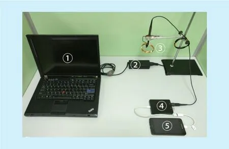
Fig. 1. Photograph of the experiment platform.
Even in the mandatory access control model, Malicious users can still be able to build a covert channel from high to low security level computers for sensitive information transmission, as shown in Figure 2. High security level and low security level between users modify and perceive the value of the shared variable or the attribute passing information. TCSEC standard uses TCB (trusted computing base) to represent the sum of all the protection mechanisms in the computer system (including hardware, firmware and software), responsible for the implementation of security policy. Wang et al. [9] have mentioned that covert channels can represent as TCB triples:

Where:variableis the variable in the system;PAhis the TCB primitive that modifies thisvariableand has a higher security level;PViis the TCB primitive that perceives this variable and has a low security level. The communication fromPAhtoPViis, if the system security policy is not allowed, then thePAhtoPVicommunication channel is called a covert channel.
Thevariablein the tuple
of convert channel can represent different attributes in the system. Whenvariablerepresents the storage attribute, the covert channel is the storage covert channel. For example, in the resource depletion channel,variablemeans that it can be modified and perceived by the shared resource. When represents the attributes of CPU timing or response time, then the covert channel is the timing covert channel.
2.2 Air-gapped covert channels
Over the years, Researchers have discovered a variety type of air-gapped covert channels. According to the different transmission methods,air-gapped covert channels can be divided into electromagnetic, optical, acoustic and thermal channels.
•Electromagnetic
In 1985, van Eck [10] showed a way to launch the so-called TEMPEST (Transient Electromagnetic Pulse Emanation Standard)exploits using affordable devices. He succeeded in capturing electromagnetic radiation signals at a considerable distance from a video card and reconstructing the image in another modified TV set. AirHopper [11], proposed a malware designed to leak air-gapped computer’s data to nearby mobile phones by generating FM radio signals from video cards. In 2105, Guri et al. Proposed GSMem malware[12], which has the ability to leak data by the computer’s RAM bus. The USBee [13] using the USB and GPIO bus to generate electromagnetic interference. Matyunin et al. used the magnetic field sensor of the mobile device as a covert channel [14]. Johannes et al. [15]present a method to abuse anti-EMI features of a processor to create a covert channel on the physical layer. Article [16] discussed other electromagnetic and magnetic covert channels.
•Optical
In the optical field, Sepetnitsky et al. [17]discussed the risk of intentional information leakage through optical signals sent from the keyboard and screen LEDs. Lopes et al. [18]proposed a new approach to air-gapped data infiltration using malicious storage devices that transmit data through flickering infrared LEDs without malware infection. VisiSploit[19] is another optical covert channel, through the so-called “invisible picture” on the LCD screen to pass information to distant cameras.

Fig. 2. Example of covert channel.
•Acoustic
In order not to be aware of its communication process, acoustic covert channel usually through the near-ultrasound to achieve the communication process. Hanspach et al. [20]achieved a near-ultrasonic covert channel through a laptop computer’s microphone and speaker. Lee et al. [21] elaborated on the concept of communication through imperceptible sounds. The article Fansmitter [22] and Disk-Filtration [23] created a novel covert channel through the sound generated by the computer’s cooling fan and hard drive at work.
•Thermal
BitWhisper [24] is a special convert channel that utilizes a temperature sensor on a computer’s motherboard. It can achieve twoway communication between air-gapped computers. However, due to temperature conductivity and other factors, the communication rate is very low (8bits per hour), almost impossible to achieve meaningful communication.
Our method, Powermitter, uses emissions produced by the switching power supply of the pervasive digital devices. Table 1 provides a comparison of these covert channels.
As can be seen from table 1, the BitWhisper of thermal covert channel, its transmission rate is too low (8bit / hour) to be used in the real scene to pass valid information. The acoustic covert channel, although not requiring special transmission and reception equipment, can be easily detected due to its sound characteristics. Similarly, based on the optical covert channel, visible light LED is also easy to be perceived and detected, even if the use of infrared LED, but it need to modify the firmware, in most cases can not be achieved,and the optical channel is easy to be shielded obscure. AirHopper implementation requires the help of Display Cable, which is not exist in laptop computers. USBee does not require specialized equipment, but in many restrictions on USB peripherals on the air-gapped system, will not be possible to implement.GSMem uses multi-channel memory to produce the electromagnetic radiation. The bus outside the radiation frequency just fell in the 800Mhz mobile band to achieve covert communication. But this method can only be achieved in the ordinary computer, for those memory which working Frequency less than 800MHz, and no multi-channel controller embedded devices, cannot be achieved. The Powermitter proposed in this paper belongs to the electromagnetic covert channel, which utilizes the radiation generated by the general switching power supply, secretly transmits the data outwards, neither special transmission equipment nor special instructions are needed.On any electronic equipment equipped with switching power supply, it is almost possible to implement this covert channel with great universality and concealment.

Table I. Comparison of air-gapped covert channels
2.3 Switched-mode power supply
Switched-Mode power supply (SMPS, also known as switching power supply) is known as energy efficient power supply. It is the use of modern power electronics technology, by controlling the switch off time ratio to maintain the output voltage stability of a power supply. It has the advantages of small volume,lightweight, low power, high efficiency, and low ripple, low noise, easy expansion and high intelligence. It is widely used in electronic equipment such as computer, TV, digital intelligent terminal and so on. It represents the development direction of the power supply, and has become the mainstream products.
The typical structure of a switching power supply is shown in Figure 3, its working principle is: AC into the power supply first rectified and filtered into high voltage direct current, and then through the switching circuit and high frequency switching transformer to high frequency low voltage pulse, and then through the rectifier and filter circuit, the final output of low voltage DC power supply. At the same time, the output part of a circuit feedback to the control circuit, by controlling the PWM duty cycle to achieve the output voltage stability.
The increase of the switching frequency is beneficial to the reduction of the size of the switching power supply, the reduction of the weight and the improvement of the dynamic response. Early switching power supply frequency is only a few thousand hertz, with the power electronic devices and magnetic materials continue to improve the performance,switching frequency gradually increased.However, with the increase in switching frequency, the power of the electromagnetic interference problem has become prominent.Switching power supply, the power adjustment switch transistor works in the switch state, it generates the AC voltage and current through the circuit of other components to produce spikes and resonant interference, although the researchers on these interference to take some measures to suppress, eliminate and shield[25][26][27], there still are some radiation from the high-frequency transformer around the leak. The captured signals proposed by this paper are mainly leak from the high-frequency transformer as shown in Figure 3.

Fig. 3. Typical structure of switching power supply.
III. ADVERSARIAL ATTACK MODEL AND ASSUMPTIONS
We make the following assumptions for the adversary attack model: (1) Air-gapped computers or devices are located in a closed environment (such as a separate room), the attacker can not implement effective acoustic,optical or thermal detection, so these traditional scenes of the covert channel can not be used by attackers. (2) The attacker can only physically access and modify the device’s software or firmware once. (3) Modified computers or devices will be subject to intensive security checks by the OEM manufacturers before deployment. For the assumption (2), recent studies have shown that infection methods for these safety-isolating devices can be achieved by implementing supply chain attacks [28],social engineering techniques [29], and firmware implantation [30]. For the assumption(3), Powermitter that proposed in this paper only adjusts the CPU load, which can be done by various legal instructions. In fact, all CPU instructions will have an impact on the CPU load; the existing means of detection cannot make such a correct judgment. Moreover, in our scenario, even if the system detects changes in CPU load, but cannot perceive the external receiver. This is because the switching power supply is neither arithmetic or storage unit, nor a controllable peripheral in the conventional sense. It has no controllable GPIOs,and no memory address mapping spaces.Switching power supply as an energy supply device is only responsible for the passive operation of the system to provide the necessary power. In a variety of security audits, measurement strategies, the researchers did not classify the power supply into the scope of the security system.
At the same time, we notice that many of the switching power supplies equipping with the devices, are directly connect to the power socket on the wall, or because of the wiring length and indoor layout and other factors,their position will be closer to the building wall. As a result, these switching power sources outward radiation of electromagnetic waves, the attackers through special equipment outside of the wall may capture it. In this regard, we have made the corresponding experiment and found that when the laptop computer’s switching power supply placed close to the wall, then a coil (the diameter of 15cm, the number of turns of 10) placed outside the wall can accurately capture the emission signals of the switching power supply.
IV. THE TRANSMITTER
Lin et al. [31] have shown that the switching power supply is operating at 10Khz to 30Mhz for its external radiation signal. According to the propagation characteristics of electromagnetic waves [32], within the distance of signal waveλ/2π, belongs to the electromagnetic near field area. It is not difficult to calculate from the above data: in the area where the radiation signal of the switching power source can be detected, it belongs to the communication near field-based. In the near field communication area, the wave signal is local magneticeld-based; so the size and shape of the antenna does not have strict requirements, a simple coupling coil can capture enough magnetic field signal. An exploitation of intentional and unintentional emissions from computer components or digital devices has been studied in[33][34][35].

Fig. 4. The two different waveforms of the SMPS emission.
In the rest of this section, we describe the design and implementation of the transmitter for details. First, we discuss and analyse the correlation between the CPU load and the SMPS radiation waveform. Then we present the method of signal modulating of the binary data. Next, we propose a data frame format protocol to help the receiver demodulate the received signal. Finally, we discuss the transmission stealth and compatibility. It should be noted that the focus of this paper is to demonstrate the feasibility of this covert channel, so we will not be struggling to try all possible signal modulation and bit frame protocols.These enhancements will be the future research work.
4.1 The frequency-load correlation analysis
We propose that an SMPS can be exploited to act as a power signal emitter capable of transmitting information wirelessly, hence the project codename, Powermitter. When the CPU is working on a different load, the EMR of the SMPS is differ accordingly. As the captured waveform from a MacBook Air’s SMPS shown in Figure 4, when the payload of CPU is low, the peaks gap of the emission signal is loose, and the more load of CPU, the more tightly of the peaks. We have found that by leveraging some resource consumption calculations, it is possible to raise the load of CPU quickly. Using this observation, we are able to modulate binary data over the EMR signals of the SMPS by adjusting the load of CPU.
As we can see, the spike interval can be used to characterize the current CPU load.In order to facilitate the subsequent signal modulation analysis and description. We experimented with three different types of computers: (1) Lenovo R400 laptop computer(with Intel P8700 CPU, will be referred as“R400” later); (2) Intel Next Unit of Computing DC53427HYE (with Intel Core i5-3427U,will be referred as “NUC” later); (3) Apple MacBook Pro (with Intel Core i7-2640M, will be referred as “MBP” later).
We managed them to work under 10% and 100% of the CPU load, and then measure the interval between the spikes and take the reciprocal of the interval to get the corresponding frequency. The energy distribution varieties of the according frequencies are illustrated as followinggures.
Figure 5 shows the frequency distribution of R400. At the 10% load status, the frequency distribution is scattered. But very concentrated when CPU is 100% load.
Figure 6 shows the frequency distribution of NUC. As we can see, the frequency distribution on the power supply is quite concentrated when CPU is 10% load. When CPU is working at 100% load, the frequency distribution has two parts (mainly located near 50kHz,a small amount of distribution in the vicinity of 60kHz).
Figure 7 illustrates the MBP’s frequency distribution. We can see that its frequency range is quite different to the others.
Although the frequency distribution patterns of three computers are different, they can meet such a basic requirement that the frequencies under different loads have a large difference and that the frequency on a load has a concentrated distribution.
The calculated average values are shown in Table 2. As can be seen from the table, the computer at light load (10%) and full load(100%), the spike interval showed a large difference, while the different computers in the same load, the spike interval is more close to the frequency. This further validates the generality of switching power supplies in frequency radiation.
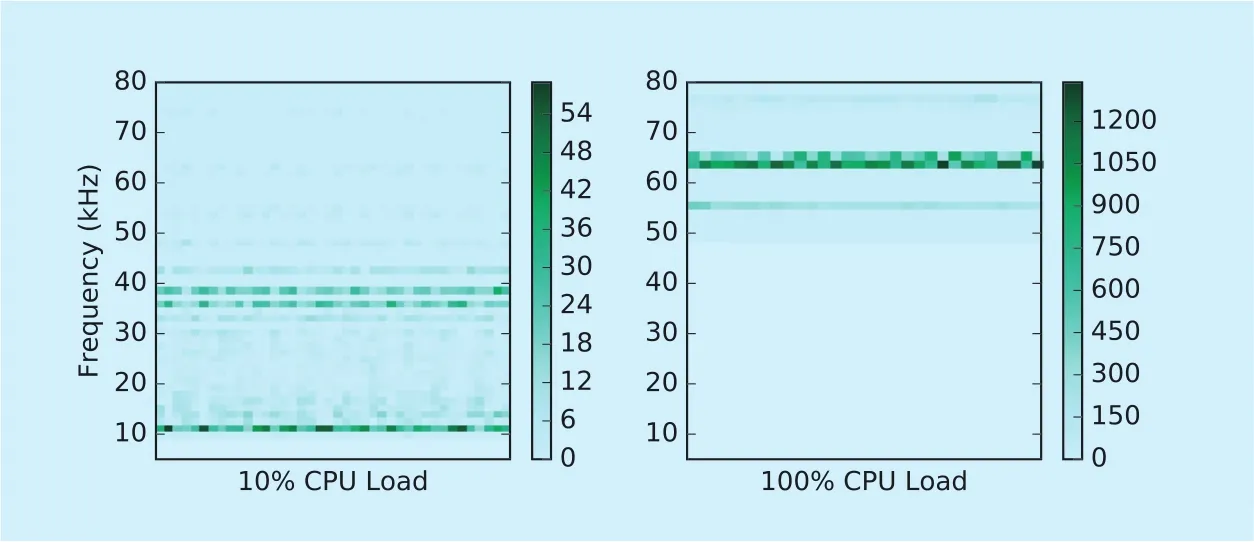
Fig. 5. The frequency distribution of R400.
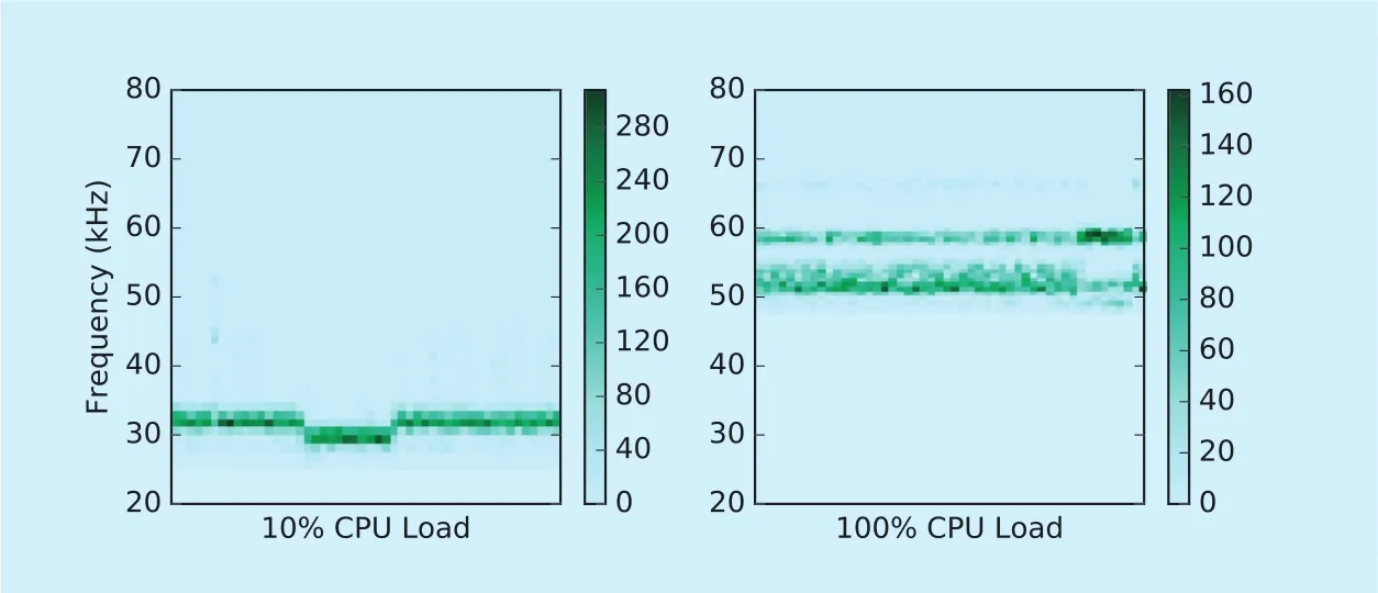
Fig. 6. The frequency energy distribution of NUC.

Fig. 7. The frequency energy distribution of MBP.
4.2 Signal modulation
Signal modulation is a process that makes some of the characteristics of a waveform change according to another waveform or signal. The information is generally the baseband signal to be transmitted (i.e., the modulated signal), which is characterized by a lower frequency, wider bandwidth and overlapping with each other, and modulation is necessary for a single channel transmission. The socalled modulation is the process of loading the baseband signal to be transmitted onto the high frequency oscillation signal, which essentially transfers the baseband signal to the high frequency carrier in order to convert the analogue or digital signal to be transmitted into a suitable channel transmission frequency signal.
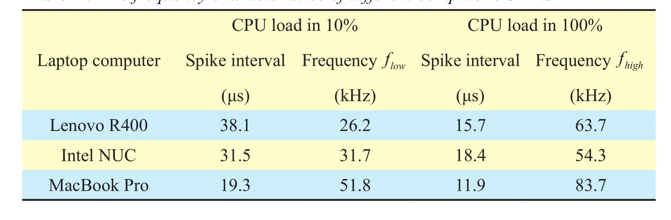
Table II. The frequency characteristics of different computer’s SMPS
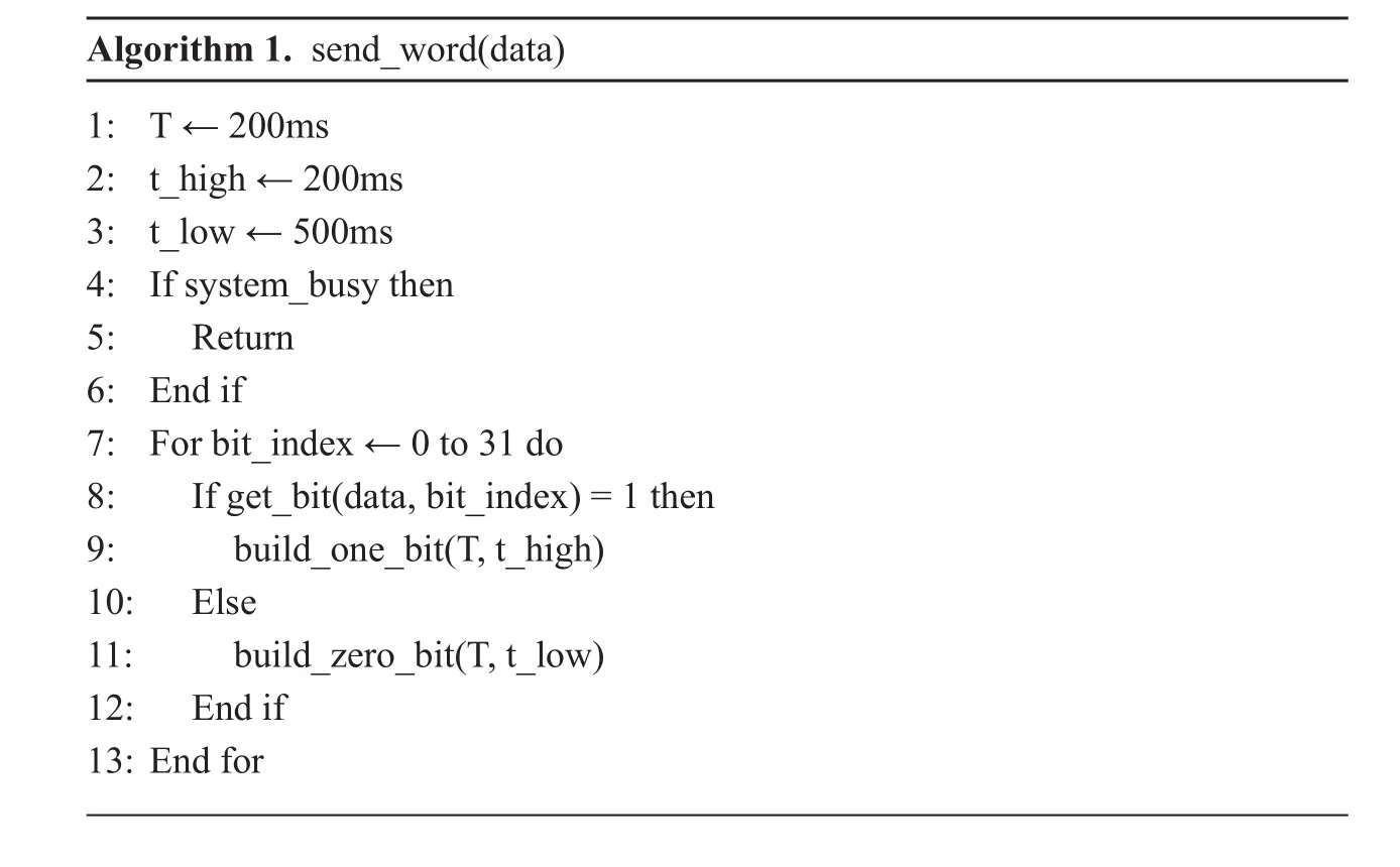
Algorithm 1. send_word(data)1: T ← 200ms 2: t_high ← 200ms 3: t_low ← 500ms 4: If system_busy then 5: Return 6: End if 7: For bit_index ← 0 to 31 do 8: If get_bit(data, bit_index) = 1 then 9: build_one_bit(T, t_high)10: Else 11: build_zero_bit(T, t_low)12: End if 13: End for
There are many ways to modulate binary data. For simplicity and as a show of feasibility, this paper uses a two-phase variant binary frequency shift keying (2P-BFSK) modulation. In standard BFSK modulation, the data is transmitted by shifting the frequency of the carrier to one of the two discrete frequencies in a binary manner. One frequency is designated as the “mark” frequency and the other is specified as the “space” frequency. Mark and space correspond to binary “1” and “0”respectively [36].
Our variation of 2P-BFSK modulations is as follows, regardless of transmission “1” or“0”; the signal both consists offhighandflowfrequency of two parts. In order to transmit “1”,first the system working at the frequency offhigh, and continue forTseconds, then let the system atflowfrequency, and persistthighseconds; In order to transmit “0”, first the system working at the frequency offhigh, and continue forTseconds, then let the system atflowfrequency, and persisttlowseconds; in order to ensure that the signal could been successfully demodulated,tlowduration is at least twice thethigh. The advantages of this modulation are:(1) the signal comes with time synchronization components, very suitable for non-handshake protocol receiver; (2) through thetlowandthightime to detect the signal “0” or “1”, suitable for different switching power supply, good to make up the difference due to the different frequency distributions.
4.3 Modulation algorithm
In order to send the signal “1” or “0”, it is necessary to let the system first enter the full load state, and consistent forTseconds. To do this we use the most CPU resources consuming calculations (i.e. encryption and decryption operation) to modulate the signal. As shown in Algorithm 1.
One of the challenges we have to face is how to get the system into a fully loaded state in the shortest possible time. At present, most computer systems are equipped with multicore CPU; one of our approaches is to assign the task to each CPU core, which can maximize the CPU utilization. At the same time,open up a number of threads, respectively, the implementation of CPU time-consuming computing (such as encryption and decryption),the system IO operation and large memory repeated handling operations.
Our implementation of 2P-BFSK modulation (Algorithm 1) in accordance with the following way: send_word () method to send a word content (32bit), Next, from line 1 to 3, we setTto 200ms,thighto 200ms andtlowto 500ms, it is clear that shorter times would provide a fast transmission rate, but the consequences of doing so will lead to an increase in bit error rate, this would be discussed later.These values cannot be unlimited, it is subject to three factors: (1)Tis related to the CPU into the full load state, due to the delay of CPU load conduction, too shortTwill lead to the system too late to enter the full load state;(2)thighwill affect the accuracy of continuous output “1”, whenthighis too short, continuous “1” will occur adhesion, resulting in data modulation failure; (3) in order to guarantee the recognition of “0” and “1”,tlowshould be different fromthigh. Due to the time accuracy of the system,tlowneeds to be at least twice as long asthigh, even in the case of time jitter,so as to ensure that the receiver is still able to correctly identify the signal.
Line 4 to 6, to determine whether the system is already in full load state, if so, then exit the send function, wait for the next entry to continue to determine the state. Line 7 to 13,bit data on the bit split, if bit is 1, build the “1”signal sequence and make the corresponding system load to generate the bit. And the similar process for bit 0.
4.4 Data frame format
As mentioned earlier, in our BFSK modulation scheme, the “0” signal depends on the idle state of the system, and the “1” signal depends on the full load state of the system.This will bring two questions: (1) the system itself is running, the load state at any time in the change, the receiver can not know whether the current state corresponds to valid data; (2)the recipient does not have the previous data reference, derive and test when the data begins to be transmitted and when it is over.
To help the receiver keep dynamic synchronization with the sender, we encapsulate the data in the frame with the concept of a transport frame in network traffic. Each frame of data consists of header information, payload real data, and the last parity check bit.As shown in Table 3, the header is used by the receiver to determine the start state of the sending process. After the header is the 12-bit length of real data. The tail one bit is the read data parity check value. The framing process takes place before data transmission. Once the frame has been built, it is passed to Algorithm 1 as the outbound data.
4.5 Transmitter stealth and compatibility
Because the transmission program transmit data by adjusting the CPU load. Therefore,the transfer logic can be hidden in any existing code, extremely difficult to be found.Because any code execution, in theory, will cause changes in CPU load, so the transmission code can run at any privilege level of the operating system. Moreover, so that the codes that changing CPU load almost have countless combinations, therefore, the transmission program can bypass the API call detection,malware behaviour detection (because the code behaviour in the existing detection environment is normal), the code fingerprint special inspection and other means of protection,making it hard to detect.
As for compatibility, the SMPS is standard equipment for modern electronic products, especially in laptop computers. In different hardware and operating systems, the attacker can easily use a variety of code to control the CPU load, and through the connected SMPS, data can be transmitted stealth out of the computer.The proposed transmitter has been implemented and successfully tested on several operating systems, including Windows 7 (64 bit), SUSE Linux enterprise server 11 SP3 and Mac OS sierra (10.12.5).
V. THE RECEIVER
In this section, we describe how to receive and decode the signal. Figure 8 illustrates the signal reception and processing framework.To retrieve the transmitted information, first,the spikes of the signal must be extracted and calculated, and then the raw data should be processed for smoothly, finally, the smoothed data should be checked and demodulated into real payload data.
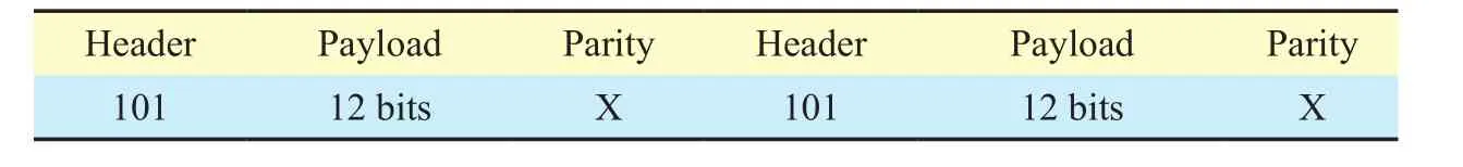
Table III. The data frame format
Reception of the transmitted data is ac-complished in the following manner: (1) The pre-processing will capture and normalize the signals emitted from SMPS. This can be achieved by properly adjusting the gain of the oscilloscope and the distance of the coil. (2)Perform wavelet transform and spikes calculation. (3) The raw data processing converts the calculated spike intervals to frequency based signals and perform low-passlter smoothing,estimate and apply the threshold, then calculate the pulse-width and extract the raw data bits. (4) The header detection and modulation process searches for bit frame header and demodulate the frame’s payload. We will describe the steps in the rest of this section.
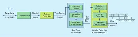
Fig. 8. The signal reception and processing framework.
5.1 Spikes detection
The original signal we captured from the SMPS has a lot of spikes, and through experimental observations, the spacing between these spikes reflects the current load of the system. When the system load heavy, the peak time interval is short; the interval is long when load is light. In theeld of medical ECG monitoring, ECG signal R-wave portrayed the human pulse signal, which we studied the waveform spikes have great similarity. As the pulse of the human body reflects the blood supply capacity of the heart, as the human body’s load increases, the pulse will become faster. By studying the characteristics of R-wave, medical workers can characterize the health of the human body. Since there is a lot of similarity between the two signals, our implementation is base on the relevant mathematical principles of R-wave detection in ECG to detect and analyse spikes in SMPS.
As shown in Figure 4, the spikes in the original waveform of the SMPS belong to the singular points, from the point of view to signal processing, in conjunction with the foregoing analysis. Wavelet transform has the characteristics of time and space localization,so wavelet analysis is a powerful tool when analysing signal singularity, singular point position and singularity size.
Mallat et al. [37] have demonstrated the possibility of link singularity detection with the wavelet transform, especially wavelet modulus maximum lines. As power spikes(P-spike) are actually the most important singularity in the received SMPS signal, the application of Mallat’s theory for P-spike detection is very appropriate.

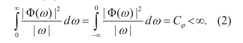
The spikes detection method depends on the following theory [38]. Letf(x)∈L2(ℝ)andϕ(x)∈L2(ℝ). We can dene the wavelet transform off(x) as:sis the scale parameter andxis the location parameter. The functionϕ(x) is said to be a wavelet if and only if its Fourier Transform Φ()ωsatises:
A modulus maximum is then any pointwhenxbelong to a right (resp. left) neighbour-hood ofx0, andwhenxbelong to the left (resp. right) neighbourhood ofx0. A connected curve in the scale space (s,x) along which all points are modulus maxima is then called a modulus maximum line.
They have also demonstrated, when the scale goes to zero, all singularities off(x)can be located by following the modulus maximum lines. And they also illustrated the way to characterize the singularities by using the modulus maximum lines.
The local regularity of a function can be measured with the Lipschitz exponent. Letnbe a positive integer andtionf(x) is said to be Lipschitzα, atx0, if and only if exists two constantsAandh0>0,and a polynomial of ordersuch that forh<h0

The superior bound of all valuesαsuch thatf(x) is Lipschitzαatx0is called Lipschitz regularity off(x) atx0. They have demonstrated that a functionf(x) is Lipschitzαatx0, if and only if there exists a constantBsuch that

Thus the Lipschitz regularity can be assessed on a logarithmic scale by the maximum slope of straight lines that remain aboveWith the higher Lipschitz exponent, comes the more regular in the function.
As described earlier, the aim of the method is to detect the modulus maximum lines. For this purpose, the use of continuous wavelet transform allows the modulus maximum lines to be followed more accurately across the scale space and thus the regularity characterization to be more precise. As in [39],the method uses the “Mexican hat” wavelet,which is the second derivative of a Gaussian:
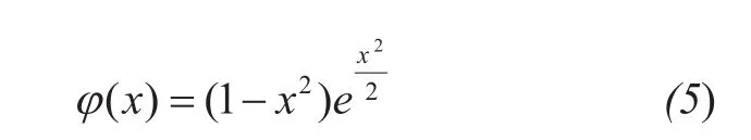
This wavelet, known as the “Mexican hat”,has been used in many data analysis tasks in the project, including: morphological features of the engineering surface, laser induced ultrasonic signal interrogation and analysis.
Using the continuous modulus maxima,the detection method can be split into the following steps: (1) Compute the continuous wavelet transform in the frequency interval asf. (2) Compute the squared modulus maxima the Wavelet Transform. Ignore those maxima lines below the pre-set thresholdv. (3) The remaining modulus maxima are taken as possible P-spike points. Between all the modulus maxima found within an interval timet, the point with the maximum coefficient value is selected as the P-spike point.
5.2 Raw data processing
Detection and calculation of the spikes is only the first step towards the modulation. The data is encoded in the time delays of the alternate frequencies of the signal. As known from section 4.1, the signal contains lots of frequency jitters. Therefor, the raw data processing are consist of three steps: (1) use low-pass filter to smooth the raw signal; (2) apply a dynamic threshold (determined based on the average of the signal) to produce a series of pulses which constitute the “0” and “1” combinations; (3)calculate the width of the pulses and estimate the number of encoded bits.
The smooth filtering of the signal has a ready-made algorithm can be used. We use a common smoothing method with low-pass filtering convolution algorithm for the raw data.After obtain smoothed data, the corresponding threshold should be applied to the processed data. As mentioned in section 4.1, the threshold value could select to 50 kHz. And then, the pulse width value could be easily calculated after threshold has been applied.
Figure 9 shows the smoothing and pulsewidth calculation result of the received signal.
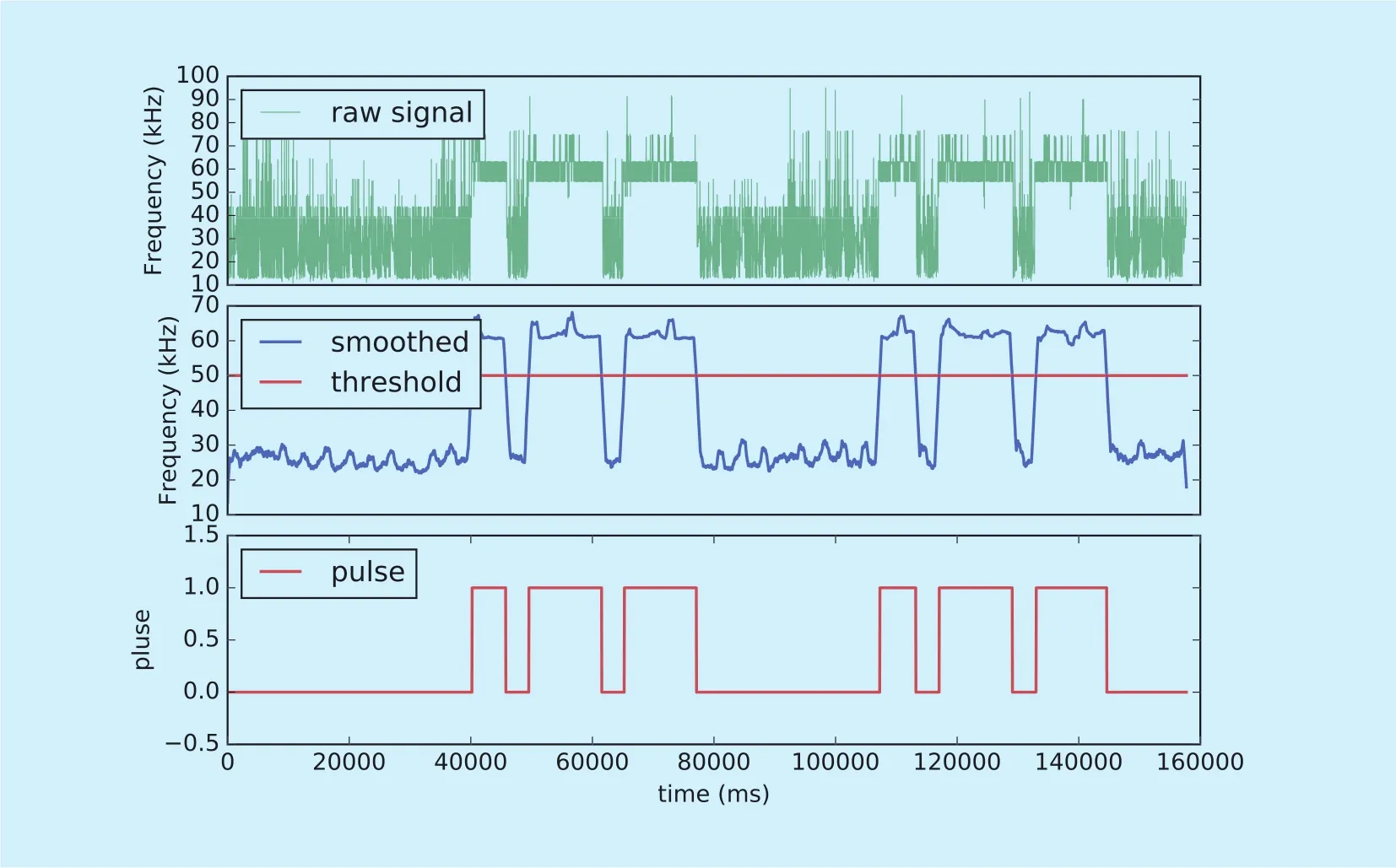
Fig. 9. Example of smooth and pulse-width calculation process.

Algorithm 2. receive_handler 1: while state = MONITOR do 2: bit_level ← read_bit_level()3: if bit_level = rising_edge then 4: set_state(HEADER)5: end if 6: end while 7: if state = HEADER then 8: if is_valid_header(raw_data) then 9: set_state(RECEIVE)10: end if 11: end if 12: if state = RECEIVE then 13: b ← demodulate_bit(raw_data)14: bit_buffer.append(b)15: if bit_buffer.length % 16 = 0 and error(bit_buffer) then 16: set_state(MONITOR)17: end if 18: end if
5.3 Header detection and demodulation
When the pulse-width value has been calculated, the next step of the implementation is the receiver handler, which will handle the header detection and data extraction process. We name this process as “receive_handler”. The receive_handler has three states: (1) monitor state for detecting the rising edge of raw data bits; (2) search for raw data header (the “101”bit stream); and (3) payloads demodulation.Monitor state is the initial state of the whole process. The pseudo code for receive_handler is presented in Algorithm 2.
VI. EXPERIMENTAL SETUP AND EVALUATION
For our proposed Powermitter covert channel,the main evaluation objectives are as follows:(1) verify whether Powermitter can covert communication effectively; (2) measure the effective distance of covert communication and discuss the factors that affect error bit rate; (3)discuss the possibility of SMPS covert channel in embedded device system.
6.1 Experiment setup
We used the DreamSourceLab DSCope virtual oscilloscope as the receiver for all experiments in this section. As for the transmitter, we used three different models of computers equipped with their original SMPS, each with a different conguration. The details of these laptop com-puters and their settings are shown in Table 4.
Without losing generality, we intended to choose three completely different computers.R400 is a regular laptop computer. NUC is an Intel’s small desktop computer, and MBP belongs to Apple’s more representative of the notebook computer. The three computers have huge difference in RAM size, CPU model and operating systems.
6.2 The feasibility of power covert channel
Table IV. Conguration of the transmitting laptop computers.
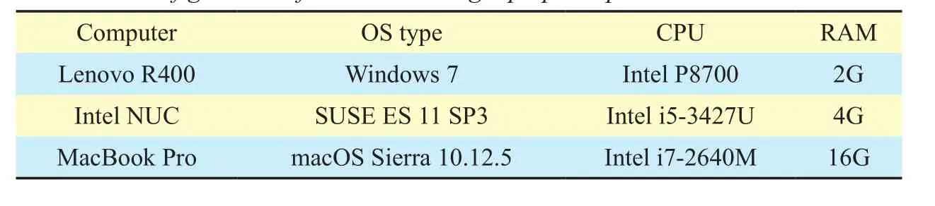
Table IV. Conguration of the transmitting laptop computers.

Fig. 11. The result on demodulated signals and the decoded data in console from Intel NUC.
In order to verify the validity of the transmission, we implement Powermitter in two separate programs. The code for the transmitter is written in shell script, and the code at the receiving side is done using python. The experimental environment is constructed according to Figure 1. The coil is placed just above the SMPS at a distance of 10 cm. The three timing parameters:T,thighandtloware: 200ms,200ms and 500ms. WhenTis less than 200ms,we cannot do error-free communication. This is determined by the characteristics of the switching power supply, whenTbecomes shorter, the CPU load change time is too short,this change is not enough to feed back to the switching power supply, then the switching power supply waveform will not follow the CPU load changes. According to Table 4, we deliberately chose three completely different computers to run Powermitter, used to test the effectiveness of this covert channel. Using the correct bit interval, we found that bits could be indeed transmitted out and then received in the oscilloscope and decoded by our python codes. Each of the test results is given in Figure 10, 11 and 12.
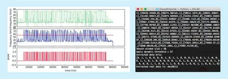
Fig. 12. The result on demodulated signals and the decoded data in console from Apple MacBook Pro.
In all cases of Figure 10-12, the hidden message was a character string, 8 bytes long,supposedly a user’s password. The message text, its ASCII code (in hexadecimal), and the binary sequence are as follows:
“abcABC12”
61, 62, 63, 41, 42, 43, 31, 32
[0, 1, 1, 0, 0, 0, 0, 1], [0, 1, 1, 0, 0, 0, 1, 0]
[0, 1, 1, 0, 0, 0, 1, 1], [0, 1, 0, 0, 0, 0, 0, 1]
[0, 1, 0, 0, 0, 0, 1, 0], [0, 1, 0, 0, 0, 0, 1, 1]
[0, 0, 1, 1, 0, 0, 0, 1], [0, 0, 1, 1, 0, 0, 1, 0]
6.3 The eff ective distance of covert communication
As discussed in the previous sections, the transmission distance is highly correlated with the detection resolution of the signal spike waveforms. In order to test the relationship between the signal spike waveform and the transmission distance, we use theVppvalue in the oscilloscope (the difference between the highest signal peak and the lowest trough)as a reference. Through the experiment, we observed that when the number of turns of the coil is greater than 10, only increasing the number of turns is almost no help for the improvement of the distance. We produce three different coils with 3cm, 7cm and 15cm diameters and use them to capture the signal,through the detection ofDVppand the backgroundBVpp(oscilloscope baseline noise) ratio to measure the distance. When the ratio is close to 1, it means that the device has reached the signal-detecting limit (the distance at this moment can be approximated as the theoretical maximum of signal transmission). In the laboratory, according to Table 4, we let three computers work in the maximum load state(the maximum amplitude). Thenal result of the distance toVppratio is shown in Figure 13.
From the above results we can see, when a coil with diameter of 3 cm is used, the effective distance is not more than 20 cm. When the coil diameter is increased to 7 cm, the effective distance is increased to 25 cm. But all computers have a transmission distance of no more than 25cm. One of the reasons is that all switching power supplies now implement measures to prevent electromagnetic interference (EMI). However, when the coil diameter increased to 15cm, we found that due to the increase in diameter, the coil captured a large number of radio clutter around, when the distance increased to 30cm, the real signal has been completely submerged in the radio noise.Therefore, regardless of the number of turns and diameter of the coil becomes larger, the effective distance of such communication is not more than 30cm.
6.4 Bit error rate
Bit error rate (BER) is an important indicator of the effectiveness of wireless transmission.Since the implementation of Powermitter is heavily dependent on the load of the CPU. The uncontrolled CPU load change is therst big factor that affect the BER. Secondly, as with all wireless communication systems, baud rate and distance are the main factors that affect the BER.
(1) CPU load changes on the impact of BER.
CPU load changes are affected by various factors, such as the number of processes running in the system, the situation of network load, memory resource consumption and so on. The operating system is responsible for dynamic scheduling CPU resource allocation;we can not control these factors changes.Thus, as described in Algorithm 1, Powermitter will make a judgment on the CPU load when it is ready to send data. When the system is in a busy state, wait until it is in a light load state (CPU load is less than 10%), and then start sending a word (32bit). We can properly determine and select the gap between the CPU load, through such a strategy to steadily transmit the contents of a word. Obviously, if the CPU load is in a very unstable state, then even a word cannot be transmitted. It should be noted that the main purpose of this paper is to prove the existence of the covert channel.Therefore, we can temporarily ignore such extreme situation.
(2) The effect of baud rate on BER.

Fig. 13. The transmission distance at different coil diameter.

Fig. 14. The BER at different baud rate.
The baud rate depends on how fast we can modulate the CPU load. From the previous discussion we can see that the CPU load is affected by many uncontrollable factors, so the actual baud rate will be severely affected by these factors. We adjust the relationship between BER and baud rate by adjusting the relevant time parameters in algorithm 1. It is worth mentioning that, based on the previous discussion, we do not consider the external factors that affect CPU load, our experimental conditions based on the CPU light load environment, and we choose the coil with diameter 7cm, the distance isxed at 10cm. As Figure 14 shows. When the baud rate is less than 1,we can get a stable transmission (BER is 0).When the baud rate is 2, BER close to 10%,however, when the baud rate increased to 3,BER suddenly increased close to 80%. At this point we can not make meaningful transmission. The reason is that when the baud rate is raised, the time interval parameter at this time has been unable to guarantee the minimum rise time of the CPU load, resulting in a large number of errors in the transmission.
(3) The impact of the distance on BER.
Distance will have a greater impact on the signal to noise ratio (SNR). As discussed earlier, although the increasing diameter of the coil can increase the distance, it will bring a serious decline in SNR. Therefore, the experimental environment using 15cm coil, baud rate maintained at 1bit/s. As can be seen from Figure 15, When the distance is less than 10cm, we can get complete right data (BER is 0). When the distance increases to 25cm, BER has more than 20%. When the distance reaches to 30cm, BER soared to more than 80%, the received data has become meaningless.
6.5 The possibility of powermitter in embedded system
At present, a large number of embedded systems (such as smart phones, TV set-top boxes, home routers, etc.) are equipped with matching switching power supply. In order to explore whether these switching power supplies also exist in the proposed covert channel,we chose a common 5V travel charger for testing. We connected an adjustable load to this charger and make them to work in idle,500mA and 1000mA of the three load conditions, respectively, to measure the frequency distribution of its radiation. Figure 16 shows the testing results.
It can be seen from the abovegure, under different load, the frequency distribution has a large and precise resolution. It shows that these types of switching power supply also have the possibility of the corresponding covert channel. As the focus of this paper is to discuss the computer switching power supply covert channel problem, so the embedded system SMPS covert channel can be done as a future work.

Fig. 15. The BER at different distance.
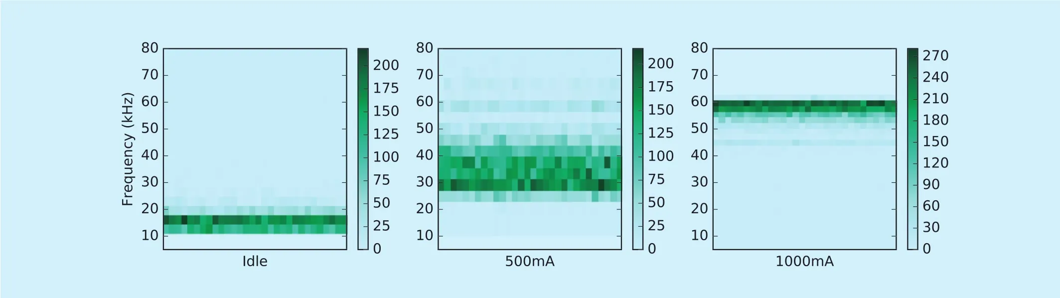
Fig. 16. The frequency distribution of 5V charger at different load.
VII. COUNTERMEASURES
With the data exfiltration method proposed in this paper, countermeasures can be considered from both technical and procedural aspects. From a technical point of view, there are two countermeasures: (1) in the hardware domain, designers could consider the methods to prevent EMI of the switching power supplies, as described in [25][26][27]. However,with the demand on the ever-shrinking size,increasing power supply capacity, switch-ing power supply operating frequency will continue to rise, the EMI will be a long-term problem, may not be able to be effectively resolved in the short term; (2) From the software point of view, detection and disruption can be considered. Since Powermitter utilizes the signal modulation achieved by CPU load changes, the system protection software can monitor changes in CPU load. However, an obvious problem is that all software running in one-system share CPU resources, and the completeness and accuracy of such monitoring may not be achieved. Moreover, the system can make “disruption software” running to disrupt the CPU’s utilization. But the cost of this approach is to sacrifice energy consumption and CPU resources, it may be difficult to implement in the real world. If there is no perfect technical solution, we can consider the countermeasures from the perspective of procedural. The following preventions can be considered: (1) using “Faraday cage” to shield the entire important equipment. But within the cage, the internal malicious attackers are still able to launch an effective attack; (2) making all the equipment from using the original power source into a centralized one. So that all the load waveform superimposed together, making the attacker harder to attack. This is the most effective protection for Powermitter. But this countermeasure requires the modification of existing equipment, and also need to pay attention to “single point of failure” problem.
VIII. CONCLUSION
In this paper, we present Powermitter, a method can exfiltrate data from “air-gapped”systems. Our main contribution is to present a covert and unattended channel, the transmitter can complete the secret data transmission without the need for specialized hardware or any special instructions. Subsequently, the transmitted data can be captured by a simple coil and demodulated and decoded in a software manner through a virtual oscilloscope.Different from the previous research work in this field, the problem which Powermitter exposed has a security risk impact on all intelligent computing devices (including set-top boxes, routers and industrial control systems,etc.) equipped with switching power supply.Subsequently, we briefly introduced the relevant technical background of the switching power supply and the physical fast frequency response characteristics of the switching transformer when system loads changes. In the design process, we have a detailed discussion on the occurrence of signals, data modulation and demodulation, smoothing filtering and final decoding. In the modulation and encoding aspect of the transmitted data, we designed a variant 2P-BFSK method with clock synchronization signal to ensure the effective communication of the data in the complicated environment where the transmitter’s signal is unstable and the receiver cannot perform clock synchronization. Based on the mainstream operating systems (including Windows, Mac OS and Linux) we implement the proof-of-concept malware. This malware encode and transmit the data only by adjusting the CPU load. It can escape the checking of the antivirus software,in behaviour scanning, instruction fingerprint matching and API detection. The receiving program modifies the software of the virtual oscilloscope by adding the special demodulation method of the signal. We have verified the malware on three computers in different hardware configurations. The final experiment shows that the covert channel based on the switching power supply radiation does exist,and the experimental data is in agreement with our viewpoints and ideas. At present, we can do covert communication at a distance of 0.25 meters and up to a maximum bit rate of 2 bit/s. This is enough for the transmission of user passwords and other confidential data. If we can make full use of the CPU in different load gear corresponding to the radiation frequency of multi-band coding, while the use of professional near field induction coil and professional amplifier to capture and decode the signal,then further enhancement on the bit rate and distance is very possible. We believe that this novel covert channel will bring new challeng-es to the air-gapped system. And it will help to raise professional awareness and academic interest.
ACKNOWLEDGEMENTS
The authors would like to thank anonymous reviewers for their detailed comments. This work was supported by the National High Technology Research and Development Program of China (“863” Program) (Grant No. 2015AA016002) and the National Basic Research Program of China (“973” Program)(Grant No. 2014CB340600).
[1] Air gap (networking). [EB/OL]. https://en.wikipedia.org/wiki/Air_gap_(networking) .2017
[2] Safety-critical system. [EB/OL]. https://en.wikipedia.org/wiki/Safety-critical_system .2017
[3] GReAT. A Fanny Equation: “I am your father,Stuxnet”. [EB/OL]. https://securelist.com/blog/research/68787/a-fanny-equation-i-am-yourfather-stuxnet/. 2015
[4] Clark, Andrew,et al., “An impact-aware defense against Stuxnet.”Proc.American Control Conference (ACC), 2013, pp. 4140-4147
[5] N. Shachtman, “Under Worm Assault, Military Bans Disks, USB Drives, ” Wired, 19 11 2008.[EB/OL]. http://www.wired.com/2008/11/army-bans- usb-d/.
[6] H. Sekiguchi, S. Seto, “Measurement of computer RGB signals in conducted emission on power leads”,Progress In Electromagnetics Research,vol. 7, 2009, pp. 51-64.
[7] B W. Lampson, “A note on the confinement problem”,Communications of the ACM, vol. 16,no. 10, 1973, pp. 613-615.
[8] S B. Lipner, “A comment on the confinement problem”,ACM SIGOPS Operating Systems Review, vol. 9, no. 5, 1975, pp. 192-196.
[9] Wang Yongji, Wu Jingzheng, Zeng Haitao,et al.,“Covert channel research”,Journal of Software,vol. 21, no. 9, 2010, pp. 2262−2288.
[10] W. Van Eck, “Electromagnetic radiation from video display units: An eavesdropping risk”,Computers & Security, vol. 4, no. 4, 1985, pp.269-286.
[11] Guri M, Kedma G, Kachlon A,et al., “AirHopper:Bridging the air-gap between isolated networks and mobile phones using radio frequencies”,Proc. Malicious and Unwanted Software: The Americas (MALWARE), 9th International Conference on, 2014, pp. 58-67.
[12] Guri M, Kachlon A, Hasson O,et al.,“GSMem:Data Exfiltration from Air-Gapped Computers over GSM Frequencies”,Proc. USENIX Security Symposium, 2015, pp. 849-864.
[13] Guri M, Monitz M, Elovici Y. “USBee: Air-gap covert-channel via electromagnetic emission from USB”,Proc. Privacy, Security and Trust (PST),14th Annual Conference on.IEEE, 2016, pp. 264-268.
[14] Matyunin N, Szefer J, Biedermann S,et al., “Covert channels using mobile device’s magnetic field sensors”,Proc. Design Automation Conference (ASP-DAC), 21st Asia and South Pacific.IEEE, 2016, pp. 525-532.
[15] Bauer J, Schinzel S, Freiling F,et al., “Information leakage behind the curtain: Abusing anti-EMI features for covert communication”,Proc. Hardware Oriented Security and Trust (HOST), IEEE International Symposium on. IEEE, 2016, pp.130-134.
[16] Kasmi C, Esteves J L, Valembois P. “Air-gap Limitations and Bypass Techniques:“Command and Control” using Smart Electromagnetic Interferences”,THE JOURNAL ON CYBERCRIME & DIGITAL INVESTIGATIONS, vol. 1, no. 1, 2015.
[17] Sepetnitsky V, Guri M, Elovici Y. “Exfiltration of information from air-gapped machines using monitor’s LED indicator”,Proc. Intelligence and Security Informatics Conference (JISIC), IEEE Joint. IEEE, 2014, pp. 264-267.
[18] Lopes A C, Aranha D F. “Platform-agnostic Low-intrusion Optical Data Exfiltration”,Proc.ICISSP, 2017, pp. 474-480.
[19] Guri M, Hasson O, Kedma G,et al., “VisiS-ploit: An Optical Covert-Channel to Leak Data through an Air-Gap”,arXiv preprint arX-iv:1607.03946, 2016.
[20] Hanspach M, Goetz M. “On covert acoustical mesh networks in air”,arXiv preprint arX-iv:1406.1213, 2014.
[21] Lee E, Kim H, Yoon J W. “Various Threat Models to Circumvent Air-Gapped Systems for Preventing Network Attack”,Proc. International Workshop on Information Security Applications.Springer, Cham, 2015, pp. 187-199.
[22] Guri M, Solewicz Y, Daidakulov A,et al., “Fansmitter: Acoustic Data Exfiltration from (Speakerless) Air-Gapped Computers”,arXiv preprint arXiv:1606.05915, 2016.
[23] Guri M, Solewicz Y, Daidakulov A,et al., “Disk-Filtration: Data Exfiltration from Speakerless Air-Gapped Computers via Covert Hard Drive Noise”,arXiv preprint arXiv:1608.03431, 2016.
[24] Guri M, Monitz M, Mirski Y,et al., “Bitwhisper:Covert signaling channel between air-gapped computers using thermal manipulations”,Proc.Computer Security Foundations Symposium(CSF), IEEE 28th. IEEE, 2015, pp. 276-289.
[25] Chang, L. V. “Study on EMI Problem of Switching Power Supply with PFC”,Telecom Power Technology, vol. 4, no. 31, 2016.
[26] Bai Y, Yang X, Zhang D,et al., “Conducted EMI Mitigation Schemes in Isolated Switching-Mode Power Supply Without the Need of a Y-Capacitor”,IEEE Transactions on Power Electronics, vol.32, no. 4, 2017, pp. 2687-2703.
[27] Mini R L, Raghavaiah V, Murthy P V N,et al., “EMI modelling and analysis of power switching circuit”,Proc. ElectroMagnetic Interference & Compatibility (INCEMIC), International Conference on. IEEE, 2016, pp. 1-3.
[28] Chiu C H, Choi T M. “Supply chain risk analysis with mean-variance models: a technical review”,Annals of Operations Research, vol. 240, no. 2,2016, pp. 489-507.
[29] Marczak W R, Paxson V. “Social Engineering Attacks on Government Opponents: Target Perspectives”,Proceedings on Privacy Enhancing Technologies, vol. 2017, no. 2, 2017, pp. 172-185.
[30] Guillen O M, Schmidt D, Sigl G. “Practical evaluation of code injection in encrypted firmware updates”,Proc. Design, Automation & Test in Europe Conference & Exhibition (DATE), 2016.IEEE, 2016, pp. 325-330.
[31] Lin F, Chen D Y. “Reduction of power supply EMI emission by switching frequency modulation”,IEEE Transactions on Power Electronics, vol. 9,no. 1, 1994, pp. 132-137.
[32] Rappaport T S. “Wireless communications: principles and practice”,New Jersey: prentice hall PTR, 1996.
[33] Enev M, Gupta S, Kohno T,et al., “Televisions,video privacy, and powerline electromagnetic interference”,Proceedings of the 18th ACM conference on Computer and communications security. ACM, 2011, pp. 537-550.
[34] Clark S S, Mustafa H, Ransford B,et al., “Current events: Identifying webpages by tapping the electrical outlet”,Proc. European Symposium on Research in Computer Security. Springer, Berlin,Heidelberg, 2013, pp. 700-717.
[35] Yang Q, Gasti P, Zhou G,et al., “On Inferring Browsing Activity on Smartphones via USB Power Analysis Side-Channel”,IEEE Transactions on Information Forensics and Security, vol. 12,no. 5, 2017, pp. 1056-1066.
[36] Watson B. “FSK: signals and demodulation”,Watkins–Johnson Company Tech–notes, vol. 7,no. 5, 1980.
[37] Mallat S, Hwang W L. “Singularity detection and processing with wavelets”,IEEE transactions on information theory, vol. 38, no. 2, 1992, pp. 617-643.
[38] Oster J, Pietquin O, Abacherli R,et al., “A specific QRS detector for Electrocardiography during MRI: using Wavelets and Local Regularity Characterization”,Proc. Acoustics, Speech and Signal Processing, 2009. ICASSP 2009. IEEE International Conference on. IEEE, 2009, pp. 341-344.
[39] Legarreta I R, Addison P S, Reed M J,et al.,“Continuous wavelet transform modulus maxima analysis of the electrocardiogram: beat characterisation and beat-to-beat measurement”,International Journal of Wavelets, Multiresolution and Information Processing, vol. 3, no.1, 2005, pp. 19-42.
杂志排行

China Communications的其它文章
- CYBERSPACE SECURITY: FOR A BETTER LIFE AND WORK
- A Cloud-Assisted Malware Detection and Suppression Framework for Wireless Multimedia System in IoT Based on Dynamic Differential Game
- An Integration Testing Framework and Evaluation Metric for Vulnerability Mining Methods
- CAPT: Context-Aware Provenance Tracing for Attack Investigation
- Decentralized Attribute-Based Encryption and Data Sharing Scheme in Cloud Storage
- TPTVer: A Trusted Third Party Based Trusted Verifier for Multi-Layered Outsourced Big Data System in Cloud Environment