Experimental study of the effect of wear parameters on the wear behavior of A356 alloy/cow horn particulate composites
2018-03-12OchiezeNwoiOkoyeAtamuo
B.Q.Ochieze,C.C.Nwoi-Okoye,P.N.Atamuo
aLafarge Africa Plc,Mfamosing Plant,Calabar,Cross River State,Nigeria
bDepartment of Mechanical Engineering,Chukwuemeka Odumegwu Ojukwu University,Uli,Anambra State,Nigeria
1.Introduction
Aluminium matrix composites(AMCs)are potential materials for various engineering applications due to their good physical and mechanical properties[1,2].The addition of reinforcements in to the metallic matrix improves the stiffness,specific strength,wear,creep and fatigue properties compared to conventional engineering materials[3,4].In recent times,there has been increasing interest in the development of composites using low density and low cost reinforcements[5].Among low cost reinforcement materials,cow horn particles can be included since they are available in large quantities as solid waste.
An extensive review work on sliding wear behaviour of AMMCs has been studied by researchers.Natarajan[6],compared the wear behaviour of A356/25SiC MMC with that of conventional grey Cast iron when slid against automobile friction materials.The work showed that the wear resistance of the composites is higher than that of the grey cast iron and concluded that the composites can be used in the production of brake drum.Yanming and Zhou Zehua[7]reported about the tool wear and its mechanism for cutting SiC particles reinforced AMMCs.The experimental results showed that the major damage mechanism is abrasive wear on the tool flank edge for conventional tools and brittle failure for high hardness tools.It was further stated that the major factors affecting tool life were volume fraction of the SiC reinforce and its size in the composite.
Shouvik Ghosh et al.[8]reported on the wear behaviour of Al-5%SiC metal matrix composite(MMC)using Taguchi method.The composite was produced by adding 5wt%SiC using stir casting method.Wear experiments were conducted in a multi-tribotester(TR 25,Ducom,India)based on Taguchi L27 orthogonal array constructed using three levels of each of the three tribological test parameters,viz;applied load(L),speed(S)and time(T).The analysis of wear behaviour was carried out using wear depth as the response variable.ANOVA analysis was carried out to find the significant test parameters and their interactions affecting the wear behaviour.Finally,confirmation tests were carried out to validate the optimization results.Scanning electron microscopy(SEM)was done on the wear tracks to identify the wear mode of the material.
Yalcin and Akbulut[9]reported on the wear of Al-SiC by varying the volume fraction from5 to20 vol%.The results showed that wear rate increased with increase in applied load but decreased with increase in volume fraction.Miyajima and Iwai[10],reported on tribological behaviour of Al-SiC.The composites were produced by powder metallurgy and high pressure infiltration by adding 5-29%SiC.The results showed that the composites synthesis by powder metallurgy has higher wear resistance than the high-pressure infiltration.
Aigbodion et al.[11],reported on wear behaviour of Al-Cu-Mg alloy/Bagasse ash(BAp)particles composites.The Bagasse ash particles were varied from 0 to 10wt.The wear tests were conducted using pin on disc machine by varying loads from 5 to 20 N and sliding speeds of 1.26 m/s,2.51 m/s,3.77 m/s and5.02 m/s for a constant sliding distance of 5000 m.The results showed that the wear rates of the Al-Cu-Mg/BAp composites are lower than that of the matrix alloy.
Atuanya et al.[12],reported on effect of wear parameters on the wear behaviour of Al-Si-Fe alloy reinforced with breadfruit seed hull ash particles produced by double stir casting process.The wear properties of the aluminium matrix composites were studied by performing dry sliding wear test using a pin-on-disc wear tester.Experiments were conducted based on the plan of experiments generated through full factorial design of four factors-two level(42)technique.The results showed that the addition of breadfruit seed hull ash as reinforcing material in Al-Si-Fe alloy composites increase the wear resistance of the composite.The sliding wear resistance of AMCs has been reported to be considerably higher than that of the unreinforced alloys[13,14].In view of the above descriptions,an attempt has been made in this study to improve the dry sliding wear behaviour of A356 alloy reinforced with cow horn particles at different loads and speeds,such that it will be more relevant and appropriate for severe environments.
2.Experiment procedure
The aluminium alloy(A356)(see Table 1),used for the experiment was purchased from a chemical shop in South Africa.The animal horns used for the study were cow horns.The horns were obtained from abattoir at Calabar,Cross River State,Nigeria.Equipment used in this research was:electrical resistance furnace,Tribometer wear machine, grinding and polishing machine,JEOLJSM840As canningelectronmicroscope(SEM).
The bony core of the cow horn was isolated naturally from the keratin sheath.The bony core was washed,sun dried for two weeks and degreased with water-soluble stain remover(acetone)to remove any trace of marrow,blood and other substances that will inhibit proper bonding between the matrix and the reinforcement particles.The bone core was then charred at a temperature of 1150°C in the absence of oxygen using a heat treatment furnace.The charred cow horn particles(CHp)were milled to the required granules and sieved to particle size of 150μm.The XRF chemical composition of the CHp is presented in Table 2.
A356-matrix/xCHp(x=0,5,10,15,20%)composites was produced using Spark Plasma Sintering(SPS).The composites were produced at a temperature of 550°C and a pressure of 30 MPa with heating and cooling rate of 100°C/min.All the samples were produced in a closed furnace where10-2 torr vacuum was maintained throughout the duration of the experiment.Taguchi's experimental design was used for the wear evaluation.The number of process parameters and their level values are given in Table 3.
The choice of values for the parameters and their levels(minimum,intermediate,and maximum)is in line with parameters used in determining the wear behaviour of brake drum[13].The total degree of freedom for the four parameters each at three levels is 8[=4 × (3-1)]By Taguchi's,the total degree of freedom of selected orthogonal array(OA)must be greater than or equal to total degree of freedom required for the experiment.So,an L9OA(a standard three level OA)having 8(9-1)degree of freedom was selected for the analysis(Table 4).This OA has four columns and nine experimental runs.The four parameters at three levels were assigned to these four columns.
Wear test were carried out using CETR UMT-2 Tribometer.A tribometer is an instrument that is used to measure the tribological quantities such as friction coefficient,wear volume and frictional force between two sliding surfaces in contact.The instrument allows forward and backward sliding where the friction coefficient of both strokes is measured.The upper specimen is motorized by a vertical positioning system with another position encoder.
The normal load applied on the samples was 25 N at a sliding velocity of 2 m/s and 2000m sliding distance using tungsten carbide ball.The entire samples were sectioned to dimensions of 2 cm×2 cm that can be fixed securely in a fitted sample chuck.The coefficient of friction was recorded continuously during the test.
The S/N ratio was calculated as given is equation(1)for small the better

Table 1Chemical composition of the A356 alloy.

Table 2Chemical composition of the cow horn particles(CHp).
Analysis of variance(ANOVA)was also used to investigate which design parameters significantly affected the quality characteristics.The wear scar was determined using JOELJSM 5900 LV Scanning Electron Microscope.
3.Results and discussion
3.1.Friction coefficient
The results of the coefficient of friction are shown in Fig.1.The results were recorded in accordance with Table 3(S/N=Stage).All curves showed similar trend that coefficient of friction decreased with wt%CHp addition.Higher coefficient of friction was experienced by unreinforced alloy for all conditions.Because of this higher friction coefficient,the unreinforced alloy suffered higher wear rate than the reinforced materials.Unreinforced alloy underwent plastic deformation due to friction and heat generation at the sliding surface.
Due to sliding surface irregularities,the applied load caused a typical stick-slip oscillation as observed in the frictional profiles.These increases could be explained by the appearance of significant plastic deformation of the sample surface.
3.2.Wear depth
Taguchi's method was used to find out the optimum control factors for achieving the desired process output.In this research,“smaller is better”S/N ratio was chosen to find the optimum level of the factors because smaller wear loss was taken into consideration.In the research,dry sliding wear tests were carried out on the composite according to the L9 orthogonal array.Four factors such as A(wt%CHp),B(applied load),C(sliding speed)and D(sliding distance)were used.The factors and the corresponding levels are presented in Table 5.In addition,the test results were analysed using analysis of variance(ANOVA)to study the influence of the control factors on wear depth.
Tests were conducted as per the Taguchi's L9 orthogonal array and the corresponding values and S/N ratios of wear loss and coefficient of friction are presented inTable 4.The S/N ratio for each factor level is determined by averaging the S/N ratios at the corresponding level.The factor with the highest S/N ratio would give minimum wear loss.The influence of factors on wear loss has been analysed.The main effects plots for mean and S/N ratios are presented in Figs.2-3.
It was observed from Figs.2-3 that,as the weight%CHp(A)increased from 0 to 20,the wear resistance of the composites increased.Also as the applied load,speed and sliding distance increased the wear resistance of the composites decreased.It can be seen that when applied load is low,the wear loss is quite small,which increased with increase in applied load.It is quite natural for the wear rate to increase with applied load.A similar trend was also observed independently for different wear distances as a function of load and speed.With higher loads contact temperatures become high and plastic deformation occurred with consequence of very high wear[14].
Ranking of factors was determined according to the delta value which is the difference between the maximum and minimum values of S/N ratio.From the response diagram of S/N ratio(Figs.2-3)and Tables 5 and 6,it was found that the optimum level value of delta has the most influence on the response.Ranking of factors is presented in Tables 6 and 7 for wear loss.It was observed that the wt%CHp is a dominant factor on the wear loss,followed by sliding distance,applied load and speed in minimizing the wear ofthe composites.From the response diagram of S/N ratio(Fig.3),it was found that the optimum level of the factors was wt%CHp(20),applied load(10 N)sliding velocity(3 m/s)and sliding distance(2000m)in minimizing the wear loss of the composites.

Table 3Process parameters and their values at different levels.

Table 4The L9(34)Orthogonal Array(OA)parameters assigned with response.
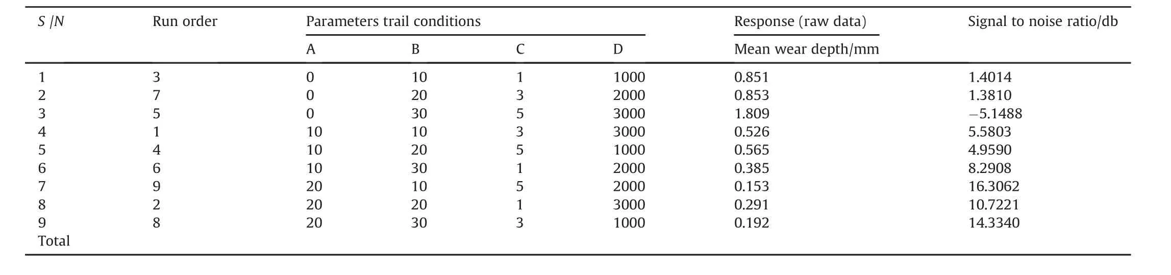
Table 5Process parameter for the wear test.
ANOVA was carried out using software package MINITAB15 for a level of significance of 5%to find the contribution of the factors on the response.The p-value was used to test the significance of each factor(see Table 8).The last column of Table 8 exemplifies the percentage contribution(Pc.%)which specifies the level of influence of the control factors on the wear loss of the composite.It can be observed that,wt%CHp(69.56%)was the major contributing factor influencing the wear loss of the composite,followed by sliding distance(13.62%),speed(10.15%)and applied load(6.48%).The higher wear resistance of the composite was observed at a load of 10 N and a sliding velocity of 3 m/s.The enhanced wear resistance at low load can be attributed to the load bearing capability of CHp and good bonding between Al alloy and the CHp.

Table 6Response Table for Signal to Noise Ratios smaller is better(smaller is better).

Table 7Response Table for Signal to mean smaller is better(smaller is better).
When the composite is subjected to higher load and sliding velocity,wear resistance tends to decrease drastically within the observed range.It could be attributed to the fact that the area of contact between sample and counter disc tends to increase due to the higher applied load,resulting in plastic shearing.Moreover,the build-up of debris which are partly embedded into either the surface of the composite sample or the counter surface,caused three body wear.
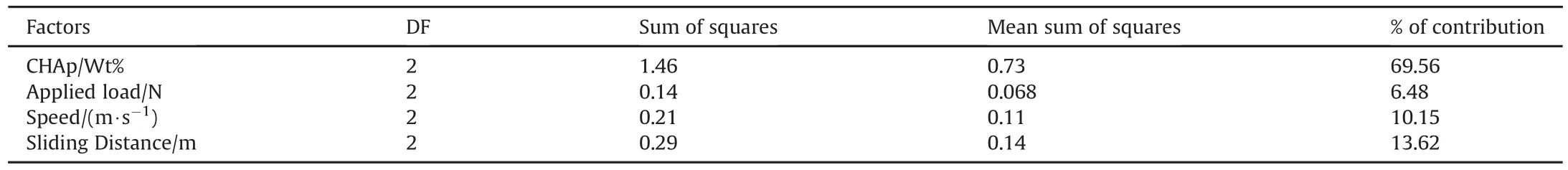
Table 8ANOVA of the process.
3.3.Wear scar
The SEM of the worn was used to establish the wear mechanism that was responsible for the improvement in the wear resistance of the composites.The wear tracks of the samples are shown in Figs.4-5.From Fig.4 it was clear that the wear track of the A356alloy shows severe plastic deformation,massive grooves,and pits.The depth of the groove:D=0.81 andL=42.85μm).By examining the groove in the middle it is clear that also delaminationbyadhesive and abrasive wear occurs to some extent.
Wear grooves spread in the sub surface region are shown in Fig.4.The morphology of the worn surfaces changed from small cracks to deep grooves.Adherence of the debris was also seen on the worn surface,which led to three body wear process and higher coefficient of friction.It can be concluded that the material removal occurred at an accelerated rate and wear mechanism changed from mild to severe wear.
Fig.5 shows the wear track of the composite.The wear scar revealed parallel line and small groves((D=0.54 andL=27.03μm).The irregular shape and size of debris observed in both surfaces indicate that adhesion and abrasion are the primary wear mechanisms for both the composites and matrix material.The wear debris indicates that under these sliding conditions,adhesive and abrasive wear happens.The debris from the composites is dull and granular(see Fig.5).The presence of CHAp decreased the extent of abrasive wear the composite.Abrasive wear requires one sliding surface to be predominantly harder than the other.When the steel disk slides along the composites surfaces,any asperities will plough through the matrix material but they will eventually encounter a CHA particle.When this happens,ploughing can no longer continue and the asperities break off.This does not happen on the matrix material surface as no reinforcements are present.
In contrast,the worn-out surfaces of the composite at optimum condition showed less damage as compared to the control alloy with less surface peeling and grooving.This confirms the remarkable reduction in wear loss and friction coefficient obtained from the wear tests as discussed above.Also,Aigbodion and Hassan[5],affirmed that the resulting effects for this lower behaviour are attributed to changes in the microstructure of the samples.Significant improvement in wear resistance was observed and drastic reduction in coefficient of friction was seen in the samples.
The SEM observation validates that the adhesion of the debris is mainly accountable for the higher wear.It is noteworthy that the frictional force increased,when sliding velocity was increased at a constant load.Hence,higher interfacial temperature induced by frictional heat,loosened the bonding at the interface between Al alloy matrix and CHp reinforcement particles,resulting in higher plastic deformation.The improvement in the wear resistance of the composites may be attributed to the toughening effect due to the incorporation of larger wt%CHp particles in the matrix.The SEM observation also validated the fact that the wear of the composites is lower than that of the alloy.
4.Conclusions
From the above results and discussions,the following conclusions are made:
1)A356 alloy reinforced with CHp exhibit better dry sliding wear resistance than the unreinforced alloy.
2)Wear rate decreased as the amount of CHp reinforcement increased in the alloy.
3)It was observed that the wt%CHAp(69.56%),was the major contributing factor that influenced the wear loss of the composite,followed by sliding distance(13.62%),speed(10.15%)and applied load(6.48%)
4)It was also found that the optimum level of the factors that minimized the wear loss of the composites were:wt%CHAp(20),applied load(10 N),sliding velocity(3 m/s)and sliding distance(2000m)
5)It was seen from the scars that severe plastic deformation,massive grooves,and pits dominated the surface of the produced A356alloy.
6)A significant improvement in wear resistance and drastic reduction in coefficient of friction was achieved as evidenced in the wear track of the samples(D=0.81 andL=42.85μm)and(D=0.54 andL=27.03μm)for A356alloy and composites at optimum conditions respectively.
[1]Atuanya CU,Aigbodion VS.Evaluation of Al-Cu-Mg alloy/bean pod ash nanoparticles synthesis by double layer feeding-stir casting method.J Alloys Compd 2014;601:251-9.
[2]Apasi A,Madakson PB,Yawas DS,Aigbodion VS.Wear behaviour of Al-Si-Fe alloy/coconut ShellAsh particulate composites.Tribol Industry 2012;34(No 1):36-43.
[3]Basavarajappa S,Chandramohan G,Subramanian R,Chandrasekar A.Dry sliding wear behaviour of Al2219/SiC metal matrix composites.Mater Science-Pol 2006;24(No.2/1):357-66.
[4]Hassan SB,Aigbodion VS.Experimental correlation between varying silicon carbide and hardness values in heat-treated Al-Si-Fe/SiC particulate composites.Mater Sci Eng A 2007;454-45:342-8.
[5]Aigbodion VS,Hassan SB.Experimental correlations between wear rate and wear parameter of Al-Cu-Mg/Bagasse Ash particulate composite.Journalof Mater&Design,Materials Des 2010;31:2177-80.
[6]Natarajan N,Vijayarangan S,Rajendran I.Wear 2006;261:812.
[7]Zehua Zhou,Yanming Quan.Mater Process Technol 2000;100:194.
[8]Ghosh Shouvik,Sutradhar Goutam,Sahoo Prasanta.Wear performance of Al-5%SiC metal matrix composites using taguchi method.J Tribol Res 2011;1(2):33-40.
[9]Yalcin Y,Akbulut H.Dry wear properties of A356-SiC particle reinforced MMCs produced by two melting routes.Mater Des 2006;27:872-81.
[10]Miyajima T,Iwai Y.Effects of reinforcements on sliding wear behavior of aluminum matrix composites.Wear 2003;255:606-16.
[11]Aigbodion VS,Hassan SB,Nyior GB,TAuse T.Effect of Bagasse ash reinforcement on the wear behavior of Al-Cu-Mg/Bagasse ash particulate composites.Acta Metall Sin Engl Lett.)April 2010;23(No.2):81-9.
[12]Atuanya CU,Onukwuli OD,Aigbodion VS.Experimental correlation of wear parameters in Al-Si-Fe alloy/breadfruit seed hull ash particulate composites.J Compos Mater 2014;48(12):1487-96.
[13]Das Sourav,Siddiqui Ameenur Rehman,Bartaria Vishvendra.Evaluation of aluminum alloy brake drum for automobile application.Int J Sci Technol Res 2011;2(11):567-71.
[14]Sudarshan,Surappa MK.Dry sliding wear of fly ash particle reinforced A356 Al composites.Wear 2008;265:349-60.
杂志排行

Defence Technology的其它文章
- Approximate ballistics formulas for spherical pellets in free flight
- An experimental study on shock wave mitigation capability of polyurea and shear thickening fluid based suspension pads
- Contemplation on some cyclic N8isomers-A DFT treatment
- Cold metal transfer(CMT)technology-An overview
- Numerical and experimental study of wave shaper effects on detonation wave front
- Microstructure,properties and hot workability of M300 grade maraging steel