Preliminary analysis of reactivity reconstruction capability based on inverse kinetics method under different initial reactivity states
2018-03-07XiaoXiangZhangGuangYaoSunJunGaoJingSongQiYang
Xiao-Xiang Zhang•Guang-Yao Sun•Jun Gao•Jing Song•Qi Yang
1 Introduction
Online reactivity monitoring is fundamental to the safe operation of nuclear power systems.For critical reactors in normal operation,the reactivity is maintained at approximately zero using multiple control strategies;moreover,it is always lower than the effective delayed neutron fraction to avoid prompt criticality.For subcritical systems with an extraneous neutron source,the reactivity is maintained within a particular subcriticality range.Under no circumstances should the variation in the reactivity lead to a delay criticality,which is used to characterize the inherent safety of source-driven subcritical systems[1].
The following dual operation modes are implemented in lead-based reactors:critical and subcritical.Owing to their excellent nuclear,thermal–hydraulic,and inherent safety properties,lead-based reactors are considered the most promising candidates for fourth-generation nuclear energy systems[2,3],accelerator-driven subcritical systems(ADSs)[4,5],and fusion-driven subcritical systems(FDSs)[6–9].The Institute of Nuclear Energy Safety Technology·FDS Team,Chinese Academy of Sciences,has made considerable progress in lead-based(pure lead or lead-based alloy coolant)reactors,including various designsofliquid–lead–lithium-cooled fusion reactors[10–13]and China LEAd-based reactor(CLEAR)[3–5].As lead-based reactors are designed for both critical and different subcritical states,it is crucial to employ a robust method to monitor the reactivity under different initial states.The inverse kinetics method can respond to delayed neutrons,which is considered to be a general method for reconstructing the reactivity of critical water reactors[14].However,the inverse kinetics method is seldom applied to subcritical reactivity reconstruction[15].Moreover,whether the inverse kinetics method can be applied to subcritical reactivity reconstruction under different initial reactivity states is unclear.Hence,in this study,the inverse kinetics method is employed for reconstructing the reactivity of a lead-based reactor under different initial reactivity states.
In the following sections,the principle behind the inverse kinetics method is first introduced.Second,for a lead-based critical reactor,the evaluation is conducted using power data obtained via the point kinetic calculation.For a lead-based subcritical reactor,the method is analyzed using power data obtained via the space–time kinetics calculation.The reactivity transient under different initial reactivity states is employed to quantitatively verify the applicability of the proposed method.
2 Principle behind the method
The exact point kinetics equation along with six delayed neutron precursor terms is given as follows[16]:

Here,p(t)can be considered the neutron density(neutrons·cm-3)or the integrated power ( W).ρ(t),β(t),and Λ(t),are the reactivity ( pcm),effective delayed neutron fraction (pcm),and prompt neutron generation time(s),respectively.is the concentration of the delayed neutron precursor(numbers·cm-3),and λkis the decay constant of the precursors.s(t)denotes the ( γ,n)or ( α,n)source when the critical reactor starts or when an extraneous high-intensity neutron source is detected for a subcritical reactor.
The above equation can be inversely transformed into Eq.(3),which is the basis for the reactivity measurement[16].

It is dif ficult to determine the power history,i.e.,the integral of the fourth term in the right-hand side of Eq.(3).To derive this term from the equation,some studies have used the Laplace transform and some others have used numerical procedures such as the Lagrange method[17],hamming method[18],and the method given elsewhere[19].In this study,the power history term is written as follows.
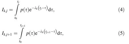
where tj+1=tj+ Δt,Δt is the time interval and tjdenotes the discrete time instants for the jth point.After integrating by parts and omitting the higher-order terms of integration and differentiation,the following discrete recursive relationship,i.e.,Eq.(6),is obtained.

In the process of transient reactivity reconstruction,the kinetic parameters,such as the effective delayed neutron fraction and prompt neutron generation time,can be assumed time independent except in the event of a major core damage accident.An optimal position for the neutron detector should be determined such that the effect of reactivity on the shape of the time-dependent flux is negligible.Based on the aforementioned assumptions,Eq.(3)can be transformed into Eq.(7),which is discrete.

Thus,based on Eq.(7),an algorithm is coded with sj+1=0 for the critical reactor,and sj+1=sj=s0,which can be calculated at the initial subcritical state,for the subcritical reactor,as shown in Eq.(8).For practical application,the initial reactivity ρ(0)could be measured using a pulsed neutron method at a lower power or using a source-jerk method at a higher power.The initial neutrondensity p(0)could be measured directly by monitoring the neutron flux at the optimal detector position.

Table 1 Reference solution for the lead-based critical reactor
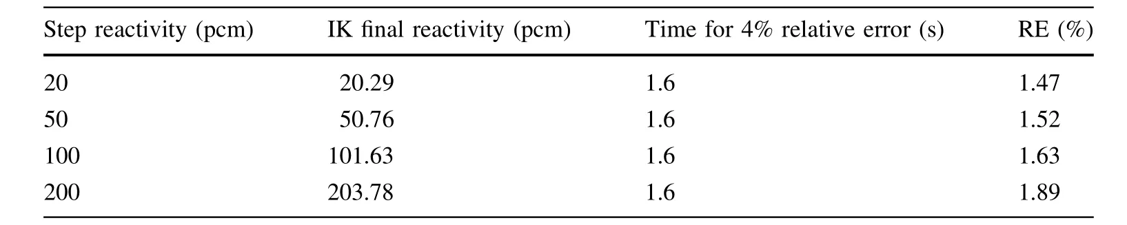
Table 2 Reactivity calculation results of step reactivity insertion for the lead-based critical reactor

3 Reactivity reconstruction for the lead-based reactor
To verify the applicability of the inverse kinetics method for the reactivity reconstruction of the lead-based reactor,a lead-based critical reactor with natural circulation[20]and a lead-based subcritical reactor,designed per the preliminary design studies of experimental acceleratordriven subcritical system(PDS-XADS)project[21],were selected as reference reactor models.
3.1 Lead-based critical reactor
A lead-based critical reactor with a capacity of 10 MWth[20]is designed to be a pool-type reactor driven via natural circulation.UO2with a mass enrichment of approximately 19.75%is selected as the fuel.At the beginning of the cycle,the effective multiplication factor keffis 1.0142.The effective delayed neutron fractions from the kth group of precursors βeff,kare 0.00025,0.00081,0.00236,0.00208,0.00168,and 0.00026,corresponding to delayed neutron decay constants λkof 0.0129,0.0311,0.134,0.331,1.26,and 3.21,respectively.The prompt neutron generation time is 0.521 μs.
The reactivity is reconstructed using the inverse kinetics method with a time interval of 0.1 s for various power forms.The power data can be obtained using a numerical solution with a point kinetics code using a high-order end floating method[22]and via an analytical solution as the reference.Subsequently,the reconstruction results of the reactivity are compared to two numerical benchmark solutions and three analytical benchmark solutions,listed in Table 1.The absolute and relative errors are de fined in Eqs.(9)and(10),respectively.

Table 2 and Fig.1a,b present the results of the inferred reactivity for the numerical benchmark cases.For positive step insertions of 20,50,100,and 200 pcm,the final reactivity was in good agreement with the induced reactivity,with the largest relative error of 1.89%,as listed in Table 2.A relative error of 4%was selected as the index to consider the real-time capability.The real-time reconstruction capability of the algorithm was good because it took only 1.6 s to obtain a relative error as low as 4%,as shown in Fig.1a.For a more complicated reactivity perturbation such as a sinusoidal insertion,this algorithm could effectively follow the reactivity variation,as shown in Fig.1b.

Fig.1 Inverse kinetics calculation for the lead-based critical reactor considering a step reactivity insertion and b sinusoidal reactivity insertion(PK code solution as the reference)
In the analytical benchmark cases,the following three power functions were considered:exponential power p(t)=ewtwith w=0.1599,ramp power p(t)=1+wt with w=1,and sinusoidal power p(t)=1+Asin(wt)with A=1 and w=0.3142.Figure 2a shows the calculated reactivity determined using the inverse kinetics method with respect to the reference solution,on the basis of the power function p(t)=e0.1599t.The relative error decreases with time after a maximum relative error of 4.12%,which was obtained at 0.4 s.The calculated reactivity is in good agreement with the reference solution,though the absolute error increases with time.The maximum absolute error is 6.88 pcm at t=15 s when the reference reactivity is 300.05 pcm.Figure 2b shows the reactivity reconstruction for the power function p(t)=1+t.The maximum absolute error found in this case is 11.70 pcm at t=1.3 s when the reference reactivity is 327.03 pcm.The relative error decreases with time as the maximum relative error of 4.13%is reached at t=0.4 s.In the next example,a sinusoidal power function p(t)=1+sin(0.3142t)is assumed,and the corresponding reactivity calculated is benchmarked against the reference solution listed in Table 1.The maximum absolute error found is 6.13 pcm at t=1.9 s when the reference reactivity is 190.38 pcm.The relative error is maintained at approximately 4%for 7.5 s,as shown in Fig.2c.

Fig.2 Inverse kinetics calculation for lead-based critical reactor with different power types:a p=exp( 0· 1599t ),b p=1+t,c p=1+sin( 0· 3142t )(analytical solution as the reference)

Fig.3 Cross-plane of the PDS-XADS[21]
The comparison results of the numerical and analytical benchmark cases show that the inverse kinetics algorithm can be used in monitoring the reactivity in real time in lead-based critical reactors by following the reactivity variation with some uncertainty.The reactivity reconstructed using the inverse kinetics method is slightly overestimated compared to the reference solution.This can be improved in the future;nevertheless,it does not affect the use of the method applied to subcritical conditions.
3.2 Lead-based subcritical reactor
The PDS-XADS[21]is a lead/bismuth-cooled subcritical system with a thermal power of 80 MW.The proton beam has an energy of 600 MeV with a maximum beam current of 6 mA.MOX fuel with a PU enrichment of 23%is considered.The effective multiplication factor at the beginning of the cycle is 0.97.There are 19 assembly regions in the center for accommodating the spallation target.There are 120 fuel assemblies in the subcritical core.Each fuel assembly has 90 fuel rods.The length of the flatto- flat fuel assembly is 137.6 mm,with an assembly gap of 4 mm.There are 165 dummy assemblies encapsulating the core for re flecting the neutrons and 12 peripheral absorb assemblies for refueling.Figure 3 and Table 3 present the cross-plane of the PDS-XADS and its related design parameters,respectively.
The neutronic transient in the subcritical system can be subdivided into two categories:reactivity transient and extraneous neutron source transient.In this study,the reactivity transient was considered with a constant external neutron source,which can be determined using the initial reactivity and neutron flux or the density under the subcritical steady state,as shown in Eq.(8).In experimental nuclear reactor physics,the initial reactivity can be determined using a pulsed neutron source method or the ADS source-jerk method[23].The steady-state neutron flux can be easily measured using neutron monitors in the core.
The super Monte Carlo program for nuclear and radiation simulation(SuperMC)[24–27]is used to obtain the subcritical neutron data,which serve as the reference for testing the inverse kinetics method.The initial reactivity was–2786 pcm at the beginning of the cycle.To test the reconstruction capability of the subcritical inverse kinetics method,different initial reactivities,such as-5486,-8367,and–12371 pcm,were selected by adjusting the plutonium mass enrichment.Four types of reactivity step insertions were considered:$0.1(1 dollar is equal to the total delayed neutron fraction β),$0.3,$0.5,and$0.9.The induced reactivity sequence comprises four phases:the first phase with a step insertion χ at 90 s,the second phase with a step insertion χ at 100 s,the third phase with a step insertion χ at 110 s,and the last phase with a linear insertion ρ =(1-0.9t)χ at 110 until 135 s.
Figure 4a,b shows the reactivity reconstruction results for an initial reactivity of-2786 pcm,corresponding to reactivity insertion values of$0.5 and$0.9,respectively.The variation in the reactivity was detected in 1 s,thereby demonstrating the monitoring performance of the proposed method.The trend in the reactivity remains largely the same after the step perturbation;hence,the average reactivity from 90 to 100 s was considered for the comparative analysis.Tables 4 and 5 list the test results of the reconstructed reactivity and the corresponding relative errorsunder different insertion values and initial reactivity states,respectively.The reactivity calculated using the inverse kinetics method was compared with the SuperMC results.

Table 3 Design parameters of the lead-based subcritical reactor related[21]

Fig.4 Inverse kinetics calculation for the lead-based subcritical reactor for insertions of a$0.5 and b$0.9 under an initial reactivity of-2786 pcm
4 Discussion
The reactivity reconstruction results obtained using the inverse kinetics method under different initial reactivity states show that this method is capable of real-time reactivity reconstruction of both critical and subcritical reactors.In the lead-based critical reactor,the reactivity reconstructed using the inverse kinetics method was compared with those reconstructed using the numerical and analytical methods.In terms of accuracy,the largest relative error was below 1.89%for an insertion of 200 pcm in the numerical benchmark cases.In the analytical benchmark cases,the largest relative error was approximately 4%.This demonstrated that the method was effective in reconstructing the reactivity of the lead-based critical reactor.
For the lead-based subcritical reactor,as in the case of the PDS-XADS,the reactivity reconstruction capability is not as high as that in the critical reactor.The absolute error depends on the initial reactivity and the corresponding induced reactivity.Fora given initialreactivity of-2786 pcm,the absolute errors were 2.14,6.89,11.44,and 19.86 pcm,corresponding to reactivity perturbations of$0.1,$0.3,$0.5,and$0.9,respectively.The absolute error tends to increase for stronger reactivity perturbations.However,the relative errors were 6.53,6.99,6.97,and 6.74%,which are approximately the same.Hence,the average relative error depends on the initial reactivity.The same trend was observed for other initial reactivities.For the same positive reactivity insertion,such as$0.5,the absolute errors were 11.44,14.74,18.94,and 24.72 pcm,corresponding to initial reactivities of-2786,-5486,-8367,and–12371 pcm,respectively.The relative errors tend to increase as follows:6.97,8.74,10.93,and 13.78%.For any other given reactivity perturbation,thesame trend was observed.This shows that both the absolute and relative errors increase with the decrease in the initial reactivity.If the relative error is controlled to be below 13.12%,the initial reactivity obtained using the inverse kinetics method can reach up to-12,371 pcm.From all the cases pertaining to the subcritical reactor,the reactivity obtained using the inverse kinetics method was globally underestimated.

Table 4 Inverse kinetics reactivity,reference reactivity under different initial reactivity ρ0and different induced reactivity Δρ

Table 5 Relative error under different initial reactivity ρ0and different induced reactivity Δρ
The inverse kinetics method is more reliable and robust for reconstructing the reactivity of critical reactors.In source-driven subcritical systems,even if the beam current remains unchanged,the effective source would change with respect to the reactivity perturbation for a given initial reactivity.This scenario indicates that the assumption of a constant external neutron source is questionable.Moreover,the inverse kinetics method is based on a simpli fied point kinetics model,wherein the variation in the shape function of the neutron flux and the complex neutron energy spectrum were neglected.Further,recent advancements show that the classical point kinetics method has limitations in the application of the neutron diffusion theory[28,29].For example,the sub-diffusive effects are neglected in this method[30].Nevertheless,this can be explained using a time-fractional point kinetics model[31,32],which has some applications[33–35].In the future,we will employ the inverse equation in the fractional point-neutron kinetics model for subcritical reactivity reconstruction.
5 Conclusion
In this study,a preliminary analysis was performed on the inverse kinetics method used for reactivity reconstruction under various initial reactivity states.The results show that the reactivity of a lead-based critical reactor was effectively reconstructed using the inverse kinetics method.However,for an initial reactivity below zero,as observed in lead-based subcritical reactors,the reactivity reconstructed using this method is globally underestimated.For a selected reactivity perturbation,both the relative and absolute errors increase with the decrease in the initial reactivity.For a particular initial reactivity,the absolute error increases with the increase in the reactivity perturbation,whereas the relative error remains the same.This deviation is due to the variation in the external neutron source,spatial-spectral effects,and sub-diffusive effects,which need to be investigated in the future.
AcknowledgementsThe authors would also like to thank the other members of the FDS team.
1.W.Johanna,Dissertation,Chalmers University of Technology,2005
2.A.Alessandro,S.Valery,F.S.Craig et al.,Overview of leadcooled fast reactor activities.Prog.Nucl.Energy 77,300–307(2014).https://doi.org/10.1016/j.pnucene.2013.11.011
3.Y.C.Wu,M.H.Wang,Q.Y.Huang et al.,Development status and prospects of lead-based reactors.Nucl.Sci.Eng.35(2),213–221(2015).https://doi.org/10.3969/j.issn.0258-0918.2015.02.004.(in Chinese)
4.Y.C.Wu,Y.Q.Bai,Y.Song et al.,Development strategy and conceptual design of China lead-based research reactor.Ann.Nucl.Energy 87,511–516(2016).https://doi.org/10.1016/j.anu cene.2015.08.015
5.Y.C.Wu,Design and R&D progress of China lead-based reactor for ADS research facility.Engineering 2(1),124–131(2016).https://doi.org/10.1016/j.eng.2016.01.023
6.Y.C.Wu,J.P.Qian,J.N.Yu,The fusion-driven hybrid system and its materialselection.J.Nucl.Mater.S307–311(2),1629–1636 (2002). https://doi.org/10.1016/S0022-3115(02)01272-2
7.Y.C.Wu,F.D.S.Team,Conceptual design activities of FDS series fusion power plants in China.Fusion Eng.Des.81(23–24),2713–2718(2006).https://doi.org/10.1016/j.fusengdes.2006.07.068
8.Y.C.Wu,F.D.S.Team,Conceptual design of the China fusion power plant FDS-II.Fusion Eng.Des.83(10),1683–1689(2008).https://doi.org/10.1016/j.fusengdes.2008.06.048
9.Y.C.Wu,J.Q.Jiang,M.H.Wang et al.,A fusion-driven subcritical system concept based on viable technologies.Nucl.Fusion 51(10),532–542(2011).https://doi.org/10.1088/0029-5515/51/10/103036
10.L.J.Qiu,Y.C.Wu,B.J.Xiao et al.,A low aspect ratio tokamak transmutation system.Nucl.Fusion 40,629–633(2000).https://doi.org/10.1088/0029/5515/40/3Y/325
11.Y.C.Wu,F.D.S.Team,Design status and development strategy of China liquid lithium-lead blankets and related material technology.J.Nucl.Mater.367–370(4),1410–1415(2007).https://doi.org/10.1016/j.jnucmat.2007.04.031
12.Y.C.Wu,F.D.S.Team,Design analysis of the China dualfunctional lithium lead(DFLL)test blanket module in ITER.Fusion Eng.Des.82(15–24),1893–1903(2007).https://doi.org/10.1016/j.fusengdes.2007.08.012
13.Y.C.Wu,F.D.S.Team,Conceptual design and testing strategy of a dual functional lithium-lead test blanket module in ITER and EAST.Nucl.Fusion 47(11),1533–1539(2007).https://doi.org/10.1088/0029-5515/47/11/015
14.H.Khala fi,S.H.Mosavi,S.M.Mirvakili,Design and construction of a digital real time reactivity meter for Tehran research reactor.Prog.Nucl.Energy 53(1),100–105(2011).https://doi.org/10.1016/j.pnucene.2010.08.001
15.S.Dulla,M.Nervo,P.Ravetto,A method for the continuous monitoring of reactivity in subcritical source-driven systems.Ann.Nucl.Energy 87,1–11(2016).https://doi.org/10.1016/j.anucene.2014.12.001
16.K.O.Ott,R.J.Neuhold,Introductory nuclear reactor dynamics(American Nuclear Society,La Grange Park,1985),pp.212–217
17.H.Malmir,N.Vosoughi,On-line reactivity calculation using Lagrange method.Ann.Nucl.Energy 62(12),463–467(2013).https://doi.org/10.1016/j.anucene.2013.07.006
18.D.S.Diaz,J.F.F.Ospina,J.A.R.Sarasty,Hamming method for solving the delayed precursor concentration for reactivity calculation.Ann.Nucl.Energy 42,47–49(2012).https://doi.org/10.1016/j.anucene.2011.12.019
19.D.S.Diaz,A.S.Martinez,F.C.Da Silva,Formulation for the calculation of reactivity without nuclear power history.J.Nucl.Sci.Technol.44(9),1149–1155(2007).https://doi.org/10.3327/Jnst.44.1149
20.Z.X.Gu,G.Wang,Z.Wang et al.,Transient analyses on loss of heat sink and overpower transient of natural circulation LBE-cooled fast reactor.Prog.Nucl.Energy 81,60–66(2015).https://doi.org/10.1016/j.pnucene.2015.01.010
21.Ansaldo Nucleare,Core con figuration speci fication of the LBECooled XADS (2001). http://nuklear-server.nuklear.kit.edu/ADOPT/ADOPT_Transfer_FZK/Files/deliverables/DEL03010.pdf.Accessed 28 Feb 2017
22.H.Q.Yuan,D.P.Hu,High-order end floating method for solving point reactor neutron kinetics equations.Nucl.Power.Eng.16(2),24–128(1995).(in Chinese)
23.F.Mellier,The MUSE experiments for subcritical neutronics validation,FIKW-CT-2000-00063(2005)
24.Y.C.Wu,F.D.S.Team,CAD-based interface programs for fusion neutron transportsimulation.Fusion Eng.Des.84(7–11),1987–1992(2009).https://doi.org/10.1016/j.fusengdes.2008.12.041
25.Y.C.Wu,J.Song,H.Q.Zheng et al.,CAD-based monte carlo program for integrated simulation of nuclear system SuperMC.Ann.Nucl.Energy 82,161–168(2014).https://doi.org/10.1016/j.anucene.2014.08.058
26.Y.C.Wu,Z.S.Xie,U.Fischer,A discrete ordinates nodal method for one-dimensional neutron transport calculation in curvilinear geometries.Nucl.Sci.Eng.133(3),350–357(1999)
27.Y.C.Wu,Z.B.Chen,L.Q.Hu et al.,Identi fication of safety gaps for fusion demonstration reactors.Nat.Energy(2016).https://doi.org/10.1038/NENERGY.2016.154
28.G.Espinosa-Paredes,J.B.Morales-Sandoval,R.Va´zquez-Rodrı´guez et al.,Constitutive laws for the neutron density current.Ann.Nucl.Energy 35(10),1963–1967(2008).https://doi.org/10.1016/j.anucene.2008.05.002
29.G.Espinosa-Paredes,R.Va´zquez-Rodrı´guez,E.del Valle Gallegos et al.,Fractional-space law for the neutron current density.Ann.Nucl.Energy 55(55),120–125(2013).https://doi.org/10.1016/j.anucene.2016.08.007
30.G.Espinosa-Paredes,M.A.Polo-Labarrios,J.Alvarez-Ramirez,Anomalous diffusion processes in nuclear reactors.Ann.Nucl.Energy 54,227–232(2013).https://doi.org/10.1016/j.anucene.2012.11.024
31.G.Espinosa-Paredes,M.A.Polo-Labarrios,E.G.Espinosa-Martinez et al.,Fractional neutron point kinetics equations for nuclear reactor dynamics.Ann.Nucl.Energy 38(2),307–330(2011).https://doi.org/10.1016/j.anucene.2010.10.012
32.G.Espinosa-Paredes,Fractional-space neutron point kinetics(FSNPK)equations for nuclear reactor dynamics.Ann.Nucl.Energy(2016).https://doi.org/10.1016/j.anucene.2016.08.007
33.M.A.Polo-Labarrios,G.Espinosa-Paredes,Numerical analysis of startup PWR with fractional neutron point kinetic equation.Prog.Nucl.Energy 60(2071),38–46(2012).https://doi.org/10.1016/j.pnucene.2012.05.003
34.T.K.Nowak,K.Duzinkiewicz,R.Piotrowski,Numerical solution analysis of fractional point kinetics and heat exchange in nuclear reactor.Nucl.Eng.Des.281,121–130(2015).https://doi.org/10.1016/j.nucengdes.2014.11.028
35.S.S.Ray,A.Patra,On the solution of the nonlinear fractional neutron point-kinetics equation with newtonian temperature feedback reactivity.Nucl.Technol.189(1),103–109(2015).https://doi.org/10.13182/NT13-148
杂志排行

Nuclear Science and Techniques的其它文章
- B4C/NRL flexible films for thermal neutron shielding
- Wetting behaviors of methanol,ethanol,and propanol on hydroxylated SiO2substrate
- Design and implementation of power and phase feedback control system for ICRH on EAST
- Data decomposition method for full-core Monte Carlo transport–burnup calculation
- New design for multi-crystal data collection at SSRF
- Design of a control system with high stability for a streak camera using isolated ADC