Active Disturbance Rejection Control for a Multiple-Flexible-Link Manipulator
2018-03-05YanfangLiuHongLiuandYaoMeng
Yanfang Liu, Hong Liu and Yao Meng
(1. State Key Laboratory of Robotics and System, Harbin Institute of Technology, Harbin 150001, China; 2. Department of Aerospace Engineering, Harbin Institute of Technology, Harbin 150001, China;3. Aerospace System Engineering Shanghai, Shanghai 201109, China)
1 Introduction
The multiple-flexible-link manipulator (MFLM) has become the key equipment of the space station and is widely used to dock spacecraft and transfer cargo. Meanwhile, due to the potential advantages of lower cost, higher operational speed, and safer operation, it has also received increasing attentions in the equipment manufacturing industry.
However, lightweight construction causes link flexibility, which results in bending and vibration of the flexible links during, at the end of, and after the maneuver. Then, the rigid motion and flexible vibration are coupled in the MFLM. Meanwhile, due to the interaction of these motions, the dynamics of the MFLM is highly coupled, nonlinear, and complex, which, in turn, leads the modeling and control of the MFLM to be a challenging task.
The modeling work is aimed at providing precise model to describe the actual MFLM’s behavior. Several approaches, such as finite element technique, assumed mode method, and lumped parameter models, have been proposed[1]. However, for the controller design application, the model is also required to be simple enough. The most common one is the adoption of the Euler-Lagrange formulation and assumed mode method, which yields closed-form expressions[1-4].
However, even for the simplified model, the controller design is still a difficult task since the controller has to follow a designed joint trajectory and cancel arms’ vibrations simultaneously. In the literature, two-loop structure control schemes were investigated. The inner loop tracks the designed trajectory and guarantees robustness of the system.While the outer loop damps links’ the vibration and deal with the unmodeled dynamics.The control scheme with proportional derivative (PD) inner-loop controller and proportional integral derivative (PID) outer-loop controller was proposed in Ref.[5]. The author further proposed an adaptive algorithm to tune PD and PID gains[6]. In Ref.[7], the outer-loop controller was designed based on the integral resonant control technique. Generalized proportional integral (GPI) controllers were proposed for both loops in Ref.[8], with disturbance compensated in the outer-loop based on an observer.The frequency identification and/or modal filter are also widely applied to the flexible-link manipulator. In Ref.[9], the author presented a control scheme, which combines the online natural frequency identification and the GPI output feedback controller, for a flexible robotic arm with unknown tip mass. A time-delay compensator combined with a modal filter was proposed in Ref.[10]. Other approaches, such as genetic learning approach[11], distributed control strategy[12], fuzzy logic control andH∞control[13]were also investigated to control the flexible-link manipulator.
The MFLM is an under-actuated system since the single actuating torque has to control the joint’s angular position and each link’s vibration.Considering this feature and noting that the links’ vibrations are relatively faster than the joints’ rotation, singular perturbation technique is a candidate solution to the control problem of such under-actuated systems. Singular perturbation approach was employed to control the manipulator with flexible-joint[14-16], flexible-link[17-18], and both flexible-link and flexible-joint[4]. It was also applied to control of the flexible manipulator actuated by pneumatic actuators[19]and cooperate trajectory tracking of two robots[20].
Active disturbance rejection control (ADRC), originally presented in Ref.[21], combines the advantages of both model-based and model-free methods and provides significant contribution to the model uncertain[22-23]. The ADRC extends the system model to represent those internal and external disturbances (total disturbance). These extended states are estimated online and used to compensate the perturbation. However, the concept of ADRC was only used for rigid manipulators[22]and flexible-joint manipulators[23].
This paper proposes an integrated control scheme consisting of ADRC and linear quadratic regulator (LQR) technique is proposed to control MFLMs. The system of MFLM is separated into two subsystems via the singular perturbed technique. Then ADRC is applied to the slow subsystem. The proposed ADRC structure employs a tracking differentiator (TD), an extended state observer (ESO), and a feedback controller with feedforward term. The TD filter is used to preshape the desired trajectory, while the ESO is utilized to estimate the internal state as well as the total disturbance. Two feedback controllers were designed, namely PD and nonlinear PD (NPD) feedback controllers. For the fast subsystem, a fast stabilizing control is designed according to the standard LQR approach.
2 MFLM Model
2.1 Dynamic Model of MFLM
The structure of MFLM is shown in Fig.1. It consists ofnflexible links,nrigid revolute joints, and a payload. Assume the MFLM is operated horizontally. Thei-th flexible link is with lengthli, linear densityρi, and rigidityEIi. The driving torqueτiis generated by the motors of thei-th joint. The rotation angle of thei-th joint is denoted asθi. The joints are considered as lumped-mass and their inertias are ignored. Thus, thei-th joint plays the role of a payload of the (i-1)-th link. The distal link is connected with a payload. The payload mass of thei-th link ismi.

Fig.1 Structure of MFLM
Utilizing Euler-Lagrange formulation and assumed mode method, the dynamics of the MFLM is modeled as[1, 3-4]

(1)

The mass matrixM(θ,q) is symmetric and positive defined. ThenM(θ,q) and its inverseN(θ,q) is partitioned as:
satisfying:

The dynamics in Eq.(1) is rewritten as:
2.2 Two-time Scale Singular Perturbation Model
A perturbation parameterμis defined as[17]:
(2)


(3)

(4)
Letμ=0, then the boundary layer correction and the slow time scale dynamics are derived as:

(5)

(6)
where the subscript ‘s’ represents the slow time scale quantities, i.e. forμ=0. The slow manifold is solved from Eq.(6)as:

(7)
Substituting Eq.(7) into Eq.(5) yields the slow subsystem as:
(8)
Letting the slow variables be constants and defining the fast variable and the fast control to bezf:=z-zsandτf:=τ-τs, the fast subsystem in Eq.(4) becomes:
whereσ=t/μis the fast time scale.
3 Design of the Composite Control Scheme
The composite controller is illustrate in Fig.2. Then, the control torqueτis given by:
τ=τs+τf
where, the slow controlτsis derived via ADRC method and the fast controlτfis designed based on LQR approach.
3.1 Active Disturbance Rejection Controller
The slow subsystem in Eq.(8)can be reformulated as:
(9)
where

represents the total disturbance, namely both the internal and external uncertainties,
(10)
is the virtual control.
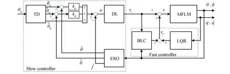
Fig.2 Composite control scheme (DL: Decoupling Law; BLC: Boundary Layer Correction)
The model is extended with an additional state to represent the total disturbance, which is estimated via ESO and further compensated.

(11)


The ESO gains can be obtained by comparing the roots of the characteristic polynomial,
λ(s)=s2+m+βi1s2+m-1+…+βi(2+m-1)s+βi(2+m)to the following polynomial
G(s)=(s+ω0)2+m
Which placed all the observer poles in the left half plane at -ω0, making the characteristic polynomial a Hurwitz-type[24].
(12)
into Eq.(11), thei-th subsystem becomes a double integrator system
Then, a simple controller combining PD feedback and a feedforward term can be designed as:
(13)
where

(14)
Thus,kpiandkdican be designed to make the above system stable and shape its response.

wherex1,x2, andurepresent state variables and the control input, respectively;his the step size;h0andrare designed filter and speed factor, respectively; and the functionffh(x1,x2,r,h0) is defined as:
Remark3.1Thanks to the separation principle, the parameters tuning for the TD filer, the ESO, and the PD controller can be taken place independently. To make the separation principle holds, the bandwidths of the TD filter and the ESO need to be relatively higher than that of the PD controller.

Then the control input of the slow subsystem can be calculated from Eq.(10) as:
τs=Mθθ,su
The termsepiandediin Eq.(13) can also be replaced by a nonlinear functionffal(x,α,δ)[21]:
法律语言承载的强制性力量是特定社会上层建筑的核心,不仅集中体现所属社会群体的主流价值理念,还综合反映了该社会政治、经济、文化等各方面占据统治地位的意识形态。这种权力表象使得法言法语更显威严神秘,令人顶礼膜拜,也因此赋予法律语言两项固有特征——权威性和约束力。由此可见,特定文化系统内法律文件的中心文本(central text)地位无可置疑。法律翻译的过程,本质上也是不同社会制度及其彰显的意识形态的直接碰撞与冲击。
Whereδ>0,0<α<1. Then a NPD controller is obtained as:
Remark3.2As shown in Fig.3, for small error, the functionffal(x,α,δ) provides high gain. In the neighborhood of origin the gain is limited by choosing a smallδ. By tuning the parametersαandδ,different gains are obtained as tracking error varies.
3.2 LQR Controller for the Fast Subsystem
The state space representation of the fast subsystem is:

where
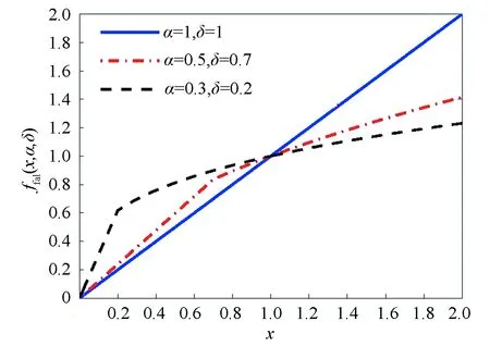
Fig.3 The property of the function ffal(x,α,δ)
Since the pair (Af,Bf) is completely controllable, optimal control technique can be applied to achieve a fast vibration depression. The object function is chosen as:
whereQfandRfare weighting matrices. Following the standard LQR design approach, the fast control is derived as:
(15)
where
Remark3.3The first term in the fast controller is derived from LQR approach, while the second term is employed to compensate for the slow control and referred to as the boundary layer correction (BLC).

4 A Case Study
4.1 Simulation Parameters
The proposed control scheme is verified via numerical study. The manipulator considered has two flexible links and each link has two assumed modes. The dynamic model is derived according to Section 2 and using the physical parameters given in Table 1, wherem1,0andm2,0refer to initial payloads. The fourth-order Runge-Kutta solver is utilized to solve the simulation. The sampling time is 0.000 5 s.

Table 1 Physical parameters

Qf=diag(100,10,10,10,10,10,10,10)
Rf=diag(100,10)
Then the feedback gain of the fast controller is calculated as:
The maneuver trajectory is designed as:
wherei=1,2,aiandωiare the desired final angular position and maneuver speed, respectively.
4.2 Relatively Slow Speed Maneuver
In the first set of simulations, relatively slow speed maneuver is tested by settingω1=ω2=2 rad/s. The desired angular positions of both joints area1=π/3 rad anda2=π/4 rad. With the initial payload only, the tracking performance of different controllers is shown in Fig.4. Herein and after, ADRC-PD refers to the controller utilizing ADRC structure and PD feedback controller and ADRC-NPD refers to that with ADRC structure and NPD feedback controller. For comparison, the PD controller proposed in Ref.[14] is designed and results are also presented in Fig.4. The superiority of the ADRC controllers is significant in reducing tracking error and vibration.Using ADRC-PD, the overshot ofθ1andθ2are 4.75% and 4.82%, respectively. And the settling times are respectively 2.49 s and 2.29 s. The performance of PD controller is worse. The overshots are 8.76% and 13.20%, and the settling times are 2.99 s and 3.17 s, respectively. The ADRC-NPD controller improves the performance slightly. The overshot decrease to 4.74% and 3.54%, and the settling times reduce to 2.05 s and 1.79 s, respectively. Seen from Figs.4(c)-(d), all the three controllers have similar performance in reducing the oscillations of both links.
If the payload increases, namelym1=m1,0+ΔMp,m2=m2,0+ΔMp,ΔMpbeing the increase of the payload, the performance is comprised in Fig.5. The responses of joints’ positions are similar. However, there is a slight vibration in the links, especially for the PD controller.
4.3 Relatively Fast Speed Maneuver
For the second set of simulations, a relatively fast speed maneuver is tested. The parameters for the desired trajectory areω1=ω2=50 rad/s. As shown in Figs.6(a)-(b), due to bandwidth limitation, all three controllers cannot follow the desired trajectory at the initial stage since the desired angular positions increase rapidly. Similar as the slow speed maneuver case, the ADRC-NPD has the smallest overshot and settling time, i.e. 0.94 s, 3.60% forθ1and 0.74 s, 7.24% forθ2. The PD controller has the worst performance, the overshot forθ1andθ2are 11.25% and 22.08% and the settling time are 2.14 s and 2.35 s, respectively. Meanwhile, seen from Figs.6(c)-(d), the ADRC-PD and ADRC-NPD smooth down the oscillations of both links more quickly than the PD controller.

Fig.4 Tracking performance at ω1=ω2=2 rad/s

Fig.5 Tracking performance with ΔMp=24.75 kg at ω1=ω2=2 rad/s

Fig.6 Tracking performance at ω1=ω2=50 rad/s
As shown in Fig.7, with an increase in the payload, the overshot ofθ1increases slightly for ADRC-PD controller and ADRC-NPD controller, whereas there is no overshot by utilizing the PD controller. However, the response of the PD controller becomes slowly. The reason is that, with these parameters, the system with PD controller becomes an over damping system. Seen from the response ofθ2, the overshot decreases for all the three controllers. However, as seen from the response of link 2, the oscillation is much larger when the PD controller is employed.
4.4 Performance at Different Maneuver Speeds
The performance of the three controllers are also tested at different maneuver speeds and summarized in Fig.8, where the maneuver speed is drawn byω=ω1=ω2. Generally, the settling time of all the three controllers decreases withω. Especially, whenω<10 rad/s, the settling time decreases rapidly. This indicates that the controllers have sufficiently wide bandwidth. However, the maneuver speed is limited by the desired maneuver trajectory. Whenω>10 rad/s, the maneuver speed is limited by the bandwidth of the controllers. Then, a fast desired maneuver trajectory can only increase the maneuver speed slightly. The ADRC-NPD can achieve the smallest settling time while that of the PD controller is the largest. Seen from Figs.8(c)-(d), for the ADRC-PD and PD controller, a faster maneuver speed generally causes a larger overshot. However, for the ADRC-NPD, the overshot increases withωfirstly and then decreases with it. This is caused by the nonlinear functionffal(x,α,δ), which yields a large gain whenxis small. When it is added to the D-term of the controller, a larger damping is obtained even when the rate of the tracking error is small, see Fig.3. Compared with PD controller, both of the ADRC-PD and ADRC-NPD controllers can realize a smaller overshot.
To further compare the tracking performance of three controllers, the index mean square error (MSE) is introduced as:
(16)
wheretfis the total time of the simulation andNis the number of samples. The MSEs for three controllers at different maneuver speed are shown in Fig.9. Generally, the MSEs of three controllers increase withωand ADRC-PD and ADRC-NPD have similar performance. Forθ2, the performance of ADRC-PD and ADRC-NPD is always better than that of PD controller. However, forθ1, the ADRC-PD and ADRC-NPD controller has smaller MSE only when the maneuver speed is small. As the desired maneuver speed increases, the bandwidth limit of ESO and TD filter will cause an obvious delay at the initial stage when the desired angular position increases rapidly, see Fig.6. As shown in Fig.10 and noting the squire operator in Eq.(16), the error caused by the delay at the initial stage results in a larger MSE index.
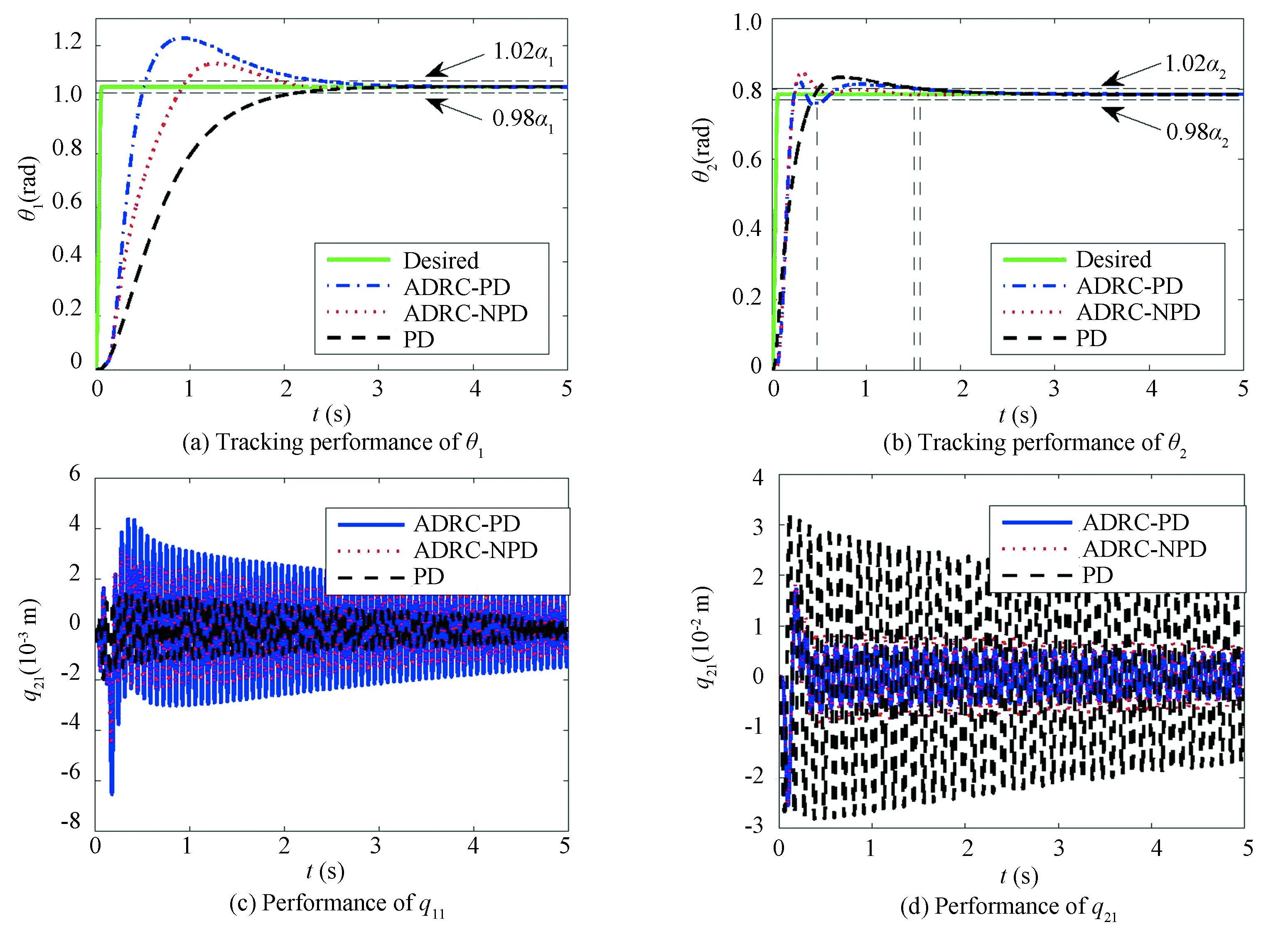
Fig.7 Tracking performance with ΔMp=24.75 kg at ω1=ω2=50 rad/s

Fig.8 Settling time and overshot of θ1 and θ2 at different maneuver speeds
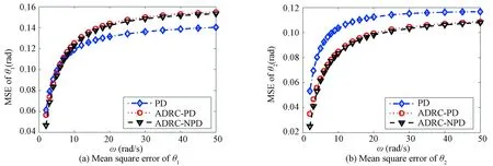
Fig.9 Summary of tracking performance at different maneuver speeds
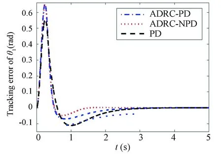
Fig.10 Tracking error of θ1 at ω1=ω2=10 rad/s
The performances of these controllers with different payloads are shown in Fig.11. For the relative slow maneuver, i.e.ω≤10 rad/s, the MSEs ofθ1andθ2is robust to the payload mass for all the three controller. However, the MSEs ofθ1andθ2increase with maneuver speed. For the response ofθ1, the ADRC-NPD controller has a better performance if the maneuver speed is small but worse than PD controller if the speed increases. The reason has been explained above. However, for the response ofθ1, the ADRC-NPD controller has better performance, no matter what the payload mass and the maneuver speed are.

Fig.11 Summary of tracking performance with different payload
5 Conclusions and Discussions
This paper focuses on application of the active disturbance rejection control (ADRC) on the multiple-flexible-link manipulator (MFLM). The dynamics of the MFLM is modeled and separated into two-time scale based on singular perturbation technique. The ADRC structure consisting of a tracking differentiator (TD) filter, an extended state observer (ESO), and a feedback controller is applied to the slow subsystem. The TD filter is employed to generate the derivation of the desired trajectory and the ESO is utilized to estimate the states as well as the total disturbance. The feedback controller can be a linear one, proportional derivation (PD) for example, or a nonlinear one, i.e. nonlinear PD controller. The controller for the fast subsystem is designed by following standard linear quadratic regulator approach. The simulation demonstrates the superiority of controllers based on ADRC structure. Generally, the ADRC structure based controllers have a superior performance on settling time, overshot, vibration cancelling, and etc. It is robust to the maneuver speed. However, the stability proof is a difficult task. And more parameters need to be adjusted. In the future, more detailed work will be carried out on the experiment research on the application of ADRC structure based controllers on the MFLM. The method how to adjust the parameters and how to handle the uncertain payload will be focused on in the next step work.
[1]Dwivedy S K, Eberhard P. Dynamic analysis of flexible manipulators, a literature review. Mechanism and Machine Theory, 2006, 41(7): 749-777.DOI: 10.1016/j.mechmachtheory.2006.01.014.
[2]Du Luca A, Siciliano B. Closed-form dynamic model of planar multilink lightweight robots. IEEE Transactions on Systems, Man and Cybernetics, 1991, 21(4): 826-839. DOI: 10.1109/21.108300.
[3]Tokhi M O, Mohamed Z, Amin S H M ,et al. Dynamic characterization of a flexible manipulator system: theory and experiments. Proceedings TENCON 2000, Kuala Lumpur. 2000. 167-172. DOI: 10.1109/TENCON.2000.892244.
[4]Subudhi B, Morris S A. Dynamic modelling, simulation and control of a manipulator with flexible links and joints. Robotics and Autonomous Systems, 2002, 41(4): 257-270.DOI:10.1016/S0921-8890(02)00295-6.
[5]Mahamood M R, Pedro O J. Hybrid PD/PID controller design for two-link flexible manipulators. Proceedings of 8th Asian Control Conference. Piscataway:IEEE Xplore, 2011. 1358-1363.
[6]Mahamood M R. Adaptive controller design for two-link flexible manipulator. IAENG Transactions on Engineering Technologies, 2014, 247: 115-128.DOI: 10.1007/978-94-007-6818-5_9.
[7]Pereira E, Aphale S S, Feliu V, et al. Integral resonant control for vibration damping and precise tip-positioning of a single-link flexible manipulator. IEEE/ASME Transactions on Mechatronics, 2011, 16(2): 232-240. DOI: 10.1109/TMECH.2009.2039713.
[8]Morales R, Feliu V, Jaramillo V. Position control of very lightweight single-link flexible arms with large payload variations by using disturbance observers. Robotics and Autonomous Systems, 2012, 60(4): 532-547.DOI: 10.1016/j.robot.2011.11.016.
[9]Becedas J, Trapero R J, Feliu V, et al. Adaptive controller for single-link flexible manipulators based on algebraic identification and generalized proportional integral control. IEEE Transactions on Systems, Man, and Cybernetics, Part B: Cybernetics, 2009, 39(3): 735-751. DOI: 10.1109/TSMCB.2008.2008905.
[10]Cai G, Lim C W. Optimal tracking control of a flexible hub-beam system with time delay. Multibody System Dynamics, 2006, 16(4): 331-350. DOI: 10.1007/s11044-006-9029-z.
[11]Sharma K S, Sutton R, Tokhi O M. Local model and controller network design for a single-link flexible manipulator. Journal of Intelligent & Robotic Systems, 2014, 74(3): 605-623. DOI: 10.1007/s10846-013-9847-1.
[12]Fareh R, Saad M. Tracking control of two-flexible-link manipulators using distributed control strategy. Proceedings of the 2013 International Conference on Control, Decision and Information Technologies (CoDIT). Piscataway:IEEE, 2013. 653-658. DOI: 10.1109/CoDIT.2013.6689620.
[13]Park W H, Yang S H, Park P Y, et al. Position and vibration control of a flexible robot manipulator using hybrid controller. Robotics and Autonomous Systems, 1999, 28(1): 31-41.DOI: 10.1016/S0921-8890(99)00027-5.
[14]Subudhi B, Morris S A. Singular perturbation approach to trajectory tracking of flexible robot with joint elasticity. International Journal of Systems Science, 2003, 34(3): 167-179. DOI: 10.1080/0020772031000135450.
[15]Khorasani K. Adaptive control of flexible-joint robots. IEEE Transactions on Robotics and Automation, 1992, 8(2): 250-267. DOI: 10.1109/70.134278.
[16]Spong M, Khorasani K, Kokotovic P. An integral manifold approach to the feedback control of flexible joint robots. IEEE Journal of Robotics and Automation, 1987, 3(4): 291-300. DOI: 10.1109/JRA.1987.1087102.
[17]Vakil M, Fotouhi R, Nikiforuk N P. Maneuver control of the multilink flexible manipulators. International Journal of Non-Linear Mechanics, 2009, 44(8): 831-844. DOI: 10.1016/j.ijnonlinmec.2009.05.008.
[18]Siciliano B, Prasad J V R, Calise A J. Output feedback two-time scale control of multilink flexible arms. Journal of Dynamic Systems, Measurement, and Control, 1992, 114(1): 70-77. DOI: 10.1115/1.2896509.
[19]Park V N, Yang S H, Park W H, et al. Position/vibration control of two-degree-of-freedom arms having one flexible link with artificial pneumatic muscle actuators. Robotics and Autonomous Systems, 2002, 40(4): 239-253.DOI: 10.1016/S0921-8890(02)00248-8.
[20]Tavasoli A, Eghtesad M, Jafarian H. Two-time scale control and observer design for trajectory tracking of two cooperating robot manipulators moving a flexible beam. Robotics and Autonomous Systems, 2009, 57(2): 212-221. DOI: 10.1016/j.robot.2008.04.003.
[21]Gao Z, Huang Y, Han J. An alternative paradigm for control system design. Proceedings of the 40th IEEE Conference on Decision and Control. Piscataway:IEEE, 2001. 4578-4585. DOI: 10.1109/CDC.2001.980926.
[22]Przybyla M, Kordasz M, Madonski R, et al. Active disturbance rejection control of a 2dof manipulator with significant modeling uncertainty. Bulletin of the Polish Academy of Sciences Technical Sciences, 2012, 60(3): 509-520. DOI: 10.2478/v10175-012-0064-z.
[23]Kordasz M, Madonski R, Przybyla M, et al. Active disturbance rejection control for a flexible-joint manipulator. Lecture Notes in Control and Information Sciences, 2011, 422: 247-256. DOI: 10.1007/978-1-4471-2343-9_21.
[24]Gao Z. Scaling and bandwidth-parameterization based controller tuning. Proceedings of the 2003 American Control Conference.Piscataway:IEEE, 2003. 6: 4989-4996. DOI: 10.1109/ACC.2003.1242516.
猜你喜欢
杂志排行

Journal of Harbin Institute of Technology(New Series)的其它文章
- Review: Natural Polymer Electrolytes for Lithium Ion Batteries
- A Practical Strategy of Unbalance Identification and Correction for 2-DOF Precision Centrifuges
- Investigation on Noise Control Technology of Ultra-High Expansion Ratio Turbine
- Prediction of Potential Disease-Associated MicroRNAs Based on Hidden Conditional Random Field
- POD Analysis and Low-Dimensional Model Based on POD-Galerkin for Two-Dimensional Rayleigh-Bénard Convection
- Analysis on Biological Stability and Influencing Factors of Northern Living District Water Distribution System