Variable stiffness design of redundantly actuated planar rotational parallel mechanisms
2017-11-20LiKangkangJiangHongzhouCuiZuoHuangQun
Li Kangkang,Jiang Hongzhou,Cui Zuo,Huang Qun
School of Mechatronics Engineering,Harbin Institute of Technology,Harbin 150001,China
Variable stiffness design of redundantly actuated planar rotational parallel mechanisms
Li Kangkang,Jiang Hongzhou*,Cui Zuo,Huang Qun
School of Mechatronics Engineering,Harbin Institute of Technology,Harbin 150001,China
Internal force;Parallel mechanisms;Redundantly actuated;Robustness;Variable stiffness
Redundantly actuated planar rotational parallel mechanisms(RAPRPMs)adapt to the requirements of robots under different working conditions by changing the antagonistic internal force to tune their stiffness.The geometrical parameters of the mechanism impact the performances of modulating stiffness.Analytical expressions relating stiffness and geometrical parameters of the mechanism were formulated to obtain the necessary conditions of variable stiffness.A novel method of variable stiffness design was presented to optimize the geometrical parameters of the mechanism.The stiffness variation with the internal force was maximized.The dynamic change of stiffness with the dynamic location of the mechanism was minimized,and the robustness of stiffness during the motion of the mechanism was ensured.This new approach to variable stiffness design can enable off-line planning of the internal force to avoid the difficulties of on-line control of the internal force.
1.Introduction
Planar parallel manipulators perform two translations along thex-andy-axes,and rotate through an angle around thez-axis,perpendicular to the plane.They have some potential advantages over serial robotic manipulators such as better accuracy,greater load capacity,and higher velocity and acceleration.1,2The redundantly actuated planar rotational parallel mechanism(RAPRPM)is a special type of planar parallel manipulator.It does not have the ability to move along thex-andy-axes,and only has a single degree of freedom,rotating around thez-axis.Meanwhile,the stiffness of rotation around thez-axis can be modulated by employing redundant actuation.The performances including inverse kinematics,forward kinematics,Jacobian matrix,workspace,singularity,and dexterity of planar parallel manipulators have been analyzed.1–4Stiffness modeling of a robotic manipulator is also one of the important issues that allows a user to evaluate its compatibility for certain tasks.5Based on biological studies of the muscular properties and the skeletal structures of fish,Cui and Jiang presented a robotic fish consisting of planar serial-parallel mechanisms,i.e.,the RAPRPMs connecting to each other in series.Itincluded rigid bodies,springs,dampers,and revolution joints.Their results showed that the swimmingperformance of the robotic fish was largely dependent on the body stiffness and the driven frequency.6Biological experiments of fish have shown that fish change their natural frequency by modulating the stiffness of their bodies to match the driving frequency.Then fish can employ resonance to improve their swimming efficiency.7–9Swimming fish that can tune their body stiffness by appropriately timed muscle contractions are able to maximize peak acceleration or swimming speed.The muscles are modeled as springs of constant stiffness.10To study the body stiffness of robotic fish consisting of planar serial-parallel mechanisms,it is important to study thestiffnessdesign and stiffnesscontrolofthe RAPRPM.Stiffness control schemes realized by employing redundant actuation can be broadly categorized as:passive stiffness control(PSC),feedback stiffness control(FSC),and active stiffness control(ASC).11,12PSC is a scheme that changes the stiffness of the mechanism by adding flexible elements to the original mechanism.13,14Because the stiffness of flexible elements cannot be changed much,the stiffness of the mechanism is changed less by using PSC.An FSC scheme chooses proportional coef ficients in the positioning joint controllers that correspond to the desired characteristics for control of the end-effector.15,16However,the modulation of proportional coef ficients of controllers may make the system unstable.An ASC scheme yields antagonistic forces in a redundantly actuated mechanism.The internal forces balance each other in a closed mechanism and do not perform any effective work,but generate end-effector stiffness.17–20An ASC scheme can significantly modulate the stiffness by modulating the internal force,which involves off-line planning of antagonistic actuator loads,so that one can obtain the desired object stiffness.21–24An ASC scheme is chosen to control the stiffness of the RAPRPM because of its advantages over other stiffness control schemes.
In addition,it is also meaningful to apply an ASC scheme to maintain constant stiffness and maximize the change of stiffness with the internal force.Sungcheul et al.introduced two indexes,one of which was suggested to make the minimum stiffness similar to the maximum stiffness at a given point and to ensure robustness and balance of the stiffness in all directions.The other index was used to maximize the stiffness in a fixed direction along thepathway.25Hence,for the RAPRPM whose stiffness changes with the dynamic location of a platform,applying an ASC scheme to enable on-line control of the internal force according to the dynamic location to keep the stiffness constant and to maximize the change of stiffness with the internal force,would increase the controlling difficulty and responding time.However,when applying an ASC scheme to enable off-line planning of the internal force to avoid the dif ficulties of on-line control,geometrical parameters are required to meet the following three requirements.Firstly,the amount of active stiffness variation with the internal force is maximum.Secondly,the proportion of active stiffness in total stiffness is maximum.Thirdly,the dynamic change of active stiffness with the rotating angle is minimum to ensure the robustness of stiffness during movement of the platform.In addition,optimization strategies such as particle swarm optimization and genetic algorithms have been widely used to minimize the power requirement for a planar parallel manipulator,26to compensate for compliance errors,5to obtain superior dexterous workspace,27,28or to maximize stiffness.29,30Similarly,the geometrical parameters are optimized to maximize the stiffness variation with the internal force and minimize the dynamic changes of total stiffness with the dynamic location of the mechanism.
2.Torsional stiffness of RAPRPM
2.1.Variable stiffness principle of RAPRPM

The torsional stiffnessKof the RAPRPM is defined as25

whereQis the torque of the top platform.
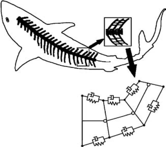
Fig.1 Compliant fish with serial-parallel redundantly actuated mechanisms.
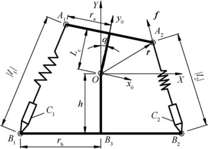
Fig.2 Schematic of a single parallel mechanism.
As shown in Fig.2,the torqueQof the top platform is defined as follows:


By substituting Eq.(2)into Eq.(1),the torsional stiffness is
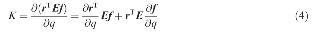
Stiffness consists of active stiffness and passive stiffness.By substituting Eq.(3)into Eq.(4),the torsional stiffnessKcan be expressed as:
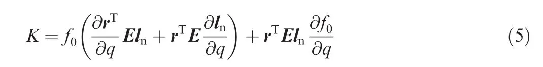
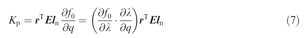
where the first item is the active stiffnessKaresulting from the internal force of the mechanisms and the second item is the passive stiffnessKpcaused by the location.Hence,the active stiffness can be given by25

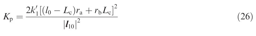
The passive stiffness is31


2.2.Active stiffness of RAPRPM
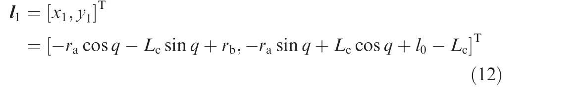
As shown in Fig.2,the torqueQof the mechanisms consists of the torqueQ1caused by the elastic legA1B1acting on the top platform and the torqueQ2caused by the elastic legA2B2acting on the top platform.That is,Q=Q1+Q2.Hence,the total torsional stiffnessKof the mechanisms consists of the torsional stiffnessK1resulting from the elastic legA1B1and the torsional stiffnessK2resulting from the elastic legA2B2.The total torsional stiffnessKis expressed as

Hence,the active stiffness and passive stiffness resulting from elastic legsA1B1andA2B2must firstly be solved before solving the total torsional stiffnessKof the mechanisms.
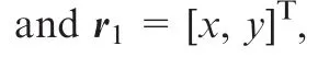


The vector of the elastic legA1B1is

The vector l1of the elastic legA1B1can be derived from Eq.(11)as below31:
The vector between the rotating centerOand the point of actionA2of the internal force f2is shown as follows:

Similarly,the vector l2of the elastic legA2B2is expressed as follows:


wheref10is the amount of internal force caused by the elastic legA1B1,l1nis the unit vector of the elastic legA1B1,and l2nis the unit vector of the elastic legA2B2.
The active stiffness resulting from the elastic legA1B1can be found by substituting Eqs.(10)and(12)into Eq.(6)as:
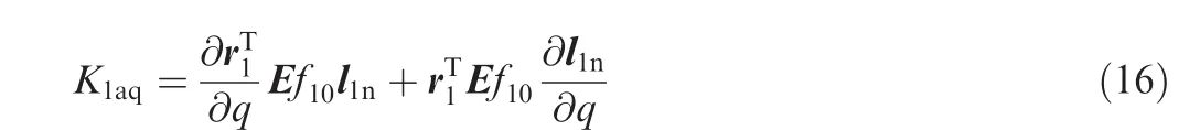
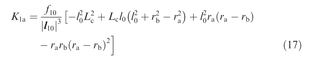
The active stiffness resulting from the elastic legA1B1at the initial position is derived from Eq.(16)as
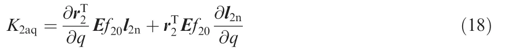
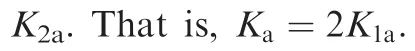
Similarly,the active stiffness resulting from the elastic legA2B2can be given as follows by substituting Eqs.(13)and(14)into Eq.(6):
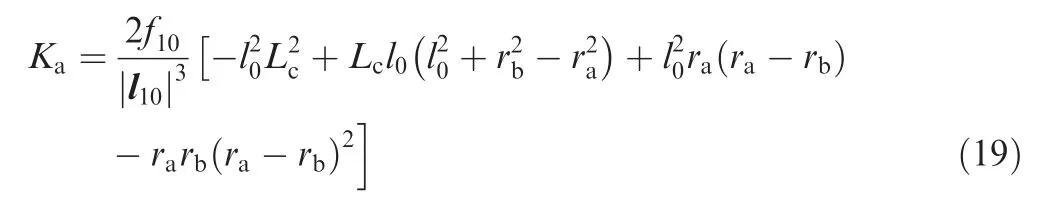


Hence,Lcin Eq.(20)is the geometrical parameter that maximizes the amount of stiffness variation with the internal force.
The internal force of the elastic leg can be given as follows:

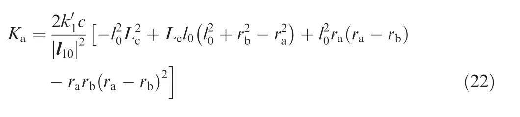
wherecis the ratio of the stretch-shortening length to the total length of the elastic leg.
The active stiffness is derived as follows by substituting Eq.(21)into Eq.(19):
2.3.Passive stiffness of RAPRPM
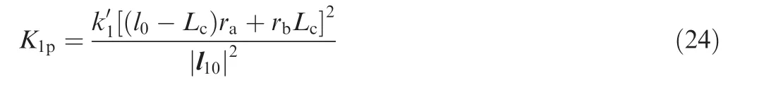
The passive stiffness resulting from the elastic legA1B1is derived by substituting Eqs.(10)and(12)into Eq.(8)as follows:

The passive stiffness at the initial position is derived from Eq.(23)as follows:
Similarly,the passive stiffness resulting from the elastic legA2B2is derived as follows by substituting Eqs.(13)and(14)into Eq.(8):


2.4.Total stiffness of RAPRPM
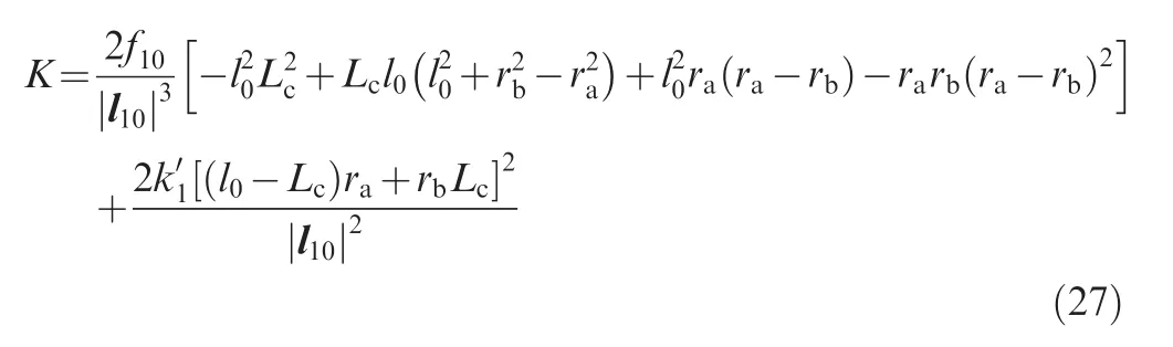
The total stiffnessKat the initial position is the sum of the total active stiffnessKaand the total passive stiffnessKp,which can be derived from Eqs.(5),(19),and Eq.(26)as:
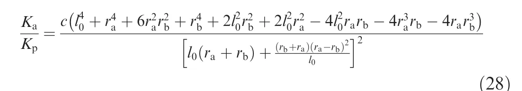
In the case of Eq.(20),the amount of active stiffness variation with the internal force is maximum.The ratio of active to passive stiffness at the initial position is derived from Eqs.(22)and(26)as:

2.5.Stiffness optimization

3.Experimental verification
The schematic of the experimental setup of the RAPRPM is shown in Fig.3.The top platform was supported by the middle rigid leg and the elastic legs on both sides.The elastic legs connected to the rotating pairs of the upper revolute joints and the lower revolute joints.The top platform rotated around the pin with a single degree-of-freedom,and the pin was also the rotating center of the top platform.The elastic legs on both sides consisted of the upper piston,the lower cylinder,and the middle spring.To modulate the active stiffness of the mechanism,the internal forces caused by the elastic legs could be modulated by moving the ring along the screw to change the length of spring stretch-shortening.The pin could be installed on different holes of the middle rigid leg to modulate the rotating center of the top platform.The bases on both ends of the elastic legs could be installed on different holes of the top platform and the fixed platform to modulate the center distances of the upper revolute joints and the lower revolute joints.The load torque was provided by the rotation of the top platform through applying a weight.The schematic of the signal collection system of the experimental setup is shown in Fig.4,in which the rotating angle was converted from the measurements of the displacement sensors on both sides above the top platform.The internal forces of the elastic legs were measured by force sensors connected to the elastic legs on both sides.The experimental torsional stiffness was obtained by the ratio of the load torque to the measured rotating angle.In addition,a SimMechanics simulation model of an RAPRPM corresponding to the experimental setup is shown in Fig.5,which consists of the top platform,elastic leg 1,elastic leg 2,and the middle rigid leg.The torque was applied to the top platform to produce a rotating angle.Torsional stiffness in the simulation was the ratio of the torque to the rotating angle.The theoretical calculation was also verified by the Matlab SimMechanics simulation.
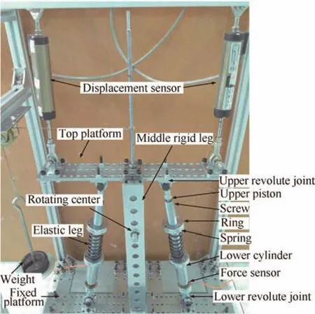
Fig.3 Experimental setup of the RAPRPM.


Fig.4 Schematic of signal collection system of experimental setup.
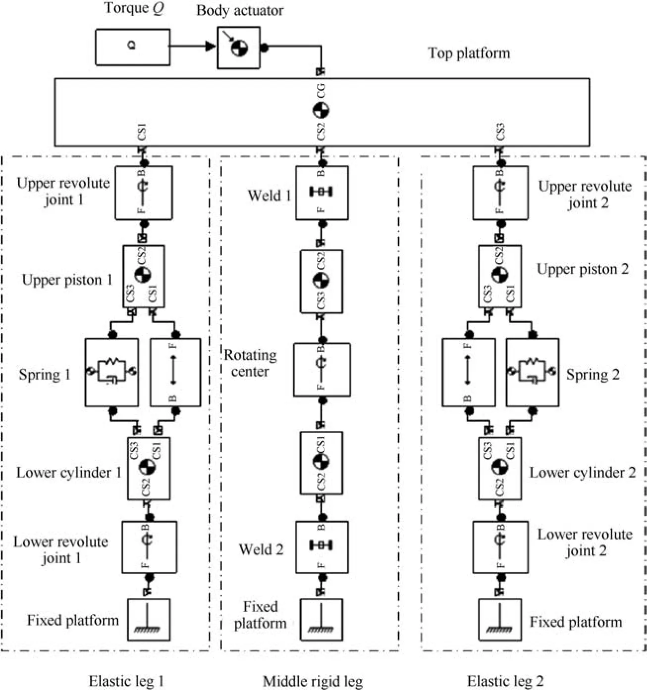
Fig.5 SimMechanics simulation model.
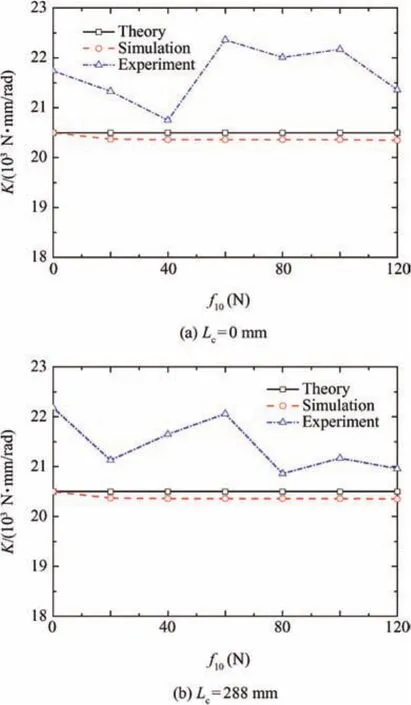
Fig.6 Total stiffness variation with internal force.
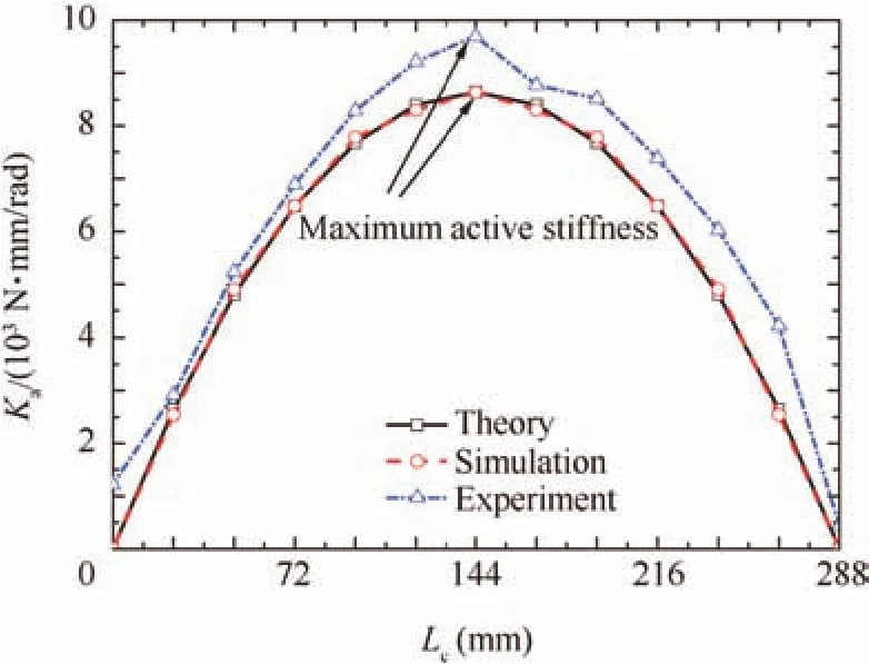
Fig.7 Active stiffness variation with Lc.

Fig.8 Ka/Kpvariation with raand rb.
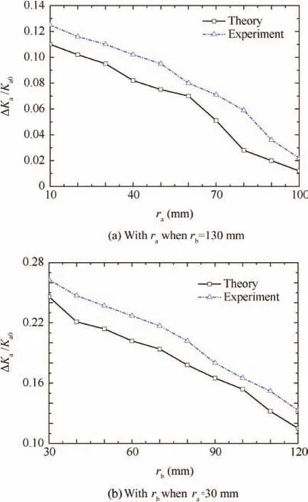
Fig.9 variation with raand rb.
4.Conclusions
(1)A novel design for stiffness variation was proposed to maximize the change of stiffness with the internal force and to minimize the dynamic change of stiffness with the dynamic location of the mechanism by optimizing the geometrical parameters of the mechanism.In addition,the relationships between the stiffness and the geometrical parameters were established.
(2)Internal force cannot tune the total torsional stiffness when the center distance of the upper revolute joints is equal to the center distance of the lower revolute joints,when the rotating center is on the top platform or on the fixed platform.The necessary condition of internal force tuning the stiffness is to avoid the situation.
(3)The positions of the rotating center maximizing the amount of stiffness variation with the internal force were obtained.The proportion of active stiffness in total stiffness rises as the center distance of the upper revolute joints or the center distance of the lower revolute joints declines.The maximum change of active stiffness during the rotation of the platform decreases as the center distance of the upper revolute joints or the center distance of the lower revolute joints increases.That is,the geometrical parameters maximize the change of stiffness with the internal force and minimize the dynamic change of total stiffness with the dynamic location of the mechanism.
Acknowledgement
This study was supported by the National Natural Science Foundation of China(No.51275127).
Appendix A.Supplementary material
Supplementary data associated with this article can be found,in the online version,at http://dx.doi.org/10.1016/j.cja.2016.07.001.
1.Kucuk S.Simulation and design tool for performance analysis of planar parallel manipulators.Simulat Trans Soc Model Simulat Int2012;88(5):542–56.
2.Merlet JP.Direct kinematics of planar parallel manipulators.Proceedings of IEEE conference 1996 on robotics and automation;1996 April 22–28;Minneapolis,Minnesota;1996.p.3744–9.
3.Kucuk S.A dexterity comparison for 3-DOF planar parallel manipulators with two kinematic chains using genetic algorithms.Mechatronics2009;19(6):868–77.
4.Merlet JP,Gosselin CM,Mouly N.Workspaces of planar parallel manipulators.Mech Mach Theory1998;33(1):7–20.
5.Klimchik A,Chablat D,Pashkevich A.Stiffness modeling for perfect and non-perfect parallel manipulators under internal and external loadings.Mech Mach Theory2014;79:1–28.
6.Cui Z,Jiang HZ.A study of the planar serial-parallel mechanism with various stiffness for a biotic compliant fish.Proceedings of the ASME 2013 international mechanical engineering congress&exposition;2013 November 13–21;San Diego,California,USA;2013.p.1–6.
7.Epps BP,Alvarado PVY,Youcef-Toumi K,Techet AH.Swimming performance of a biomimetic compliant fish-like robot.Exp Fluids2009;47(6):927–39.
8.Alvarado PV.Design of biomimetic compliant devices for locomotion in liquid environments.J Dyn Syst Meas Contr2007;128:3–13.
9.Alvarado PV.Design of biomimetic compliant devices for locomotion in liquid environments[dissertation].Massachusetts:Massachusetts Institute of Technology;2007.
10.Tytell ED,Hsu CY,Williams TL,Cohen AH,Fauci LJ.Interactions between internal forces,body stiffness,and fluid environment in a neuromechanical model of lamprey swimming.Proceedings of the 2010 national academy of sciences of the United States of America;2010.p.19832–7.
11.Dasgupta BH,Mruthyunjaya TS.Force redundancy in parallel manipulators:theoretical and practical issues.Mech Mach Theory1998;33(6):727–42.
12.Chakarov D.Study of the antagonistic stiffness of parallel manipulators with actuation redundancy.Mech Mach Theory2004;39(6):583–601.
13.Mills JK.Hybrid actuator for robot manipulators:design,control and performance.Mechatronics1993;3(1):19–38.
14.Mittal S,Tasch U,Wang Y.A redundant actuation scheme for independent modulations of stiffness and position of a robotic joint.Mech Haptic Interf1993;49:247–56.
15.Yokoi K,Kaneko M,Tanie K.Direct compliance control of parallel link manipulators.Proceedings of the 8th CISM––IFToMM symposium;Paris,France;1990.p.224–51.
16.Yokoi K,Kaneko M,Tanie K.Direct compliance control for a parallel link arm.Trans Jpn Soc Mech Eng1989;55(515):1690–6.
17.Gardner JF,Kumar V,Ho JH.Kinematics and control of redundantly actuated closed chains.Proceedings of the 1989 IEEE international conference on robotics and automation;Scottsdale;1989.p.418–24.
18.Nahon MA,Angeles J.Force optimization in redundantly actuated closed kinematic chains.Proceedings of the 1989 IEEE international conference on robotics and automation;Scottsdale;1989.p.951–6.
19.Tadokoro S.Control of parallel mechanisms.Adv Robot1993;8(6):559–71.
20.Cho W,Tesar D,Freeman RA.The dynamic and stiffness modeling of general robotic manipulator systems with antagonistic actuation.Proceedings of the 1989 IEEE international conference on robotics and automation;1989.p.1380–7.
21.Yi BJ,Freeman RA.Geometric characteristics of antagonistic stiffness in redundantly actuated mechanisms.Proceedings of the1989 IEEE international conference on robotics and automation;1993.p.654–61.
22.Yi BJ,Oh SR.Analysis of a 5-bar finger mechanism having redundant actuators with applications to stiffness.Proceedings of the 1989 IEEE international conference on robotics and automation;Albuquerque;1997.p.759–65.
23.Yi BJ,Freeman RA,Tesar D.Open-loop stiffness control of overconstrained mechanisms/robotic linkage systems.Proceedings of the 1989 IEEE international conference on robotics and automation;1989.p.1340–5.
24.Adli M,Ito K,Hanafusa H.A method for modulating the contact compliance in objects held by dual-arm robots.Proceedings of the 1995 IEEE international conference on recent advances in mechatronics;Istanbul,Turkey;1995.p.1065–72.
25.Sungcheul L,Sitae K,Woosung I,Moonki K,Jay IJ,Jongwon K.Experimental verification of antagonistic stiffness planning for a planar parallel mechanism with 2-DOF force redundancy.Robotica2011;29(7):547–54.
26.Kucuk S.Energy minimization for 3-RRR fully planar parallel manipulator using particle swarm optimization.Mech Mach Theory2013;62(4):129–49.
27.Toz M,Kucuk S.Dimensional optimization of 6-DOF 3-CCC typeasymmetricparallelmanipulator.AdvRobot2014;28(9):625–37.
28.Marc A,Roger B.The synthesis of three-degree-of-freedom planar mechanisms with revolute joints(3-RRR)for an optimal singularity-free workspace.J Robot Syst2004;21(5):259–74.
29.Chi Z,Zhang D,Xia L,Zhen G.Multi-objective optimization of stiffness and workspace for a parallel kinematic machine.Int J Mech Mater Des2012;9(3):281–93.
30.Arsenault M,Boudreau R,Arsenault M.Synthesis of planar parallel mechanisms while considering workspace,dexterity,stiffnessand singularity avoidance.JMechDes2006;128(12):69–78.
31.Shin H,Lee S,Jeong JI,Jongwon K.Antagonistic stiffness optimization of redundantly actuated parallel manipulators in a predefined workspace.Proceedings of the 1995 IEEE/ASME international conference on transactions on mechatronics;2013.p.1161–9.
32.Dai XL,Huang QT,Jiang HZ,Han JW.Kinematics analysis of a 3-dof rotational parallel mechanism.2008 international workshop on modelling,simulation and optimization;2008.p.404–7.
33.Tian TZ,Jiang HZ,Tong ZZ,He JF,Huang QT.An inertial parameter identification method of eliminating system damping effect for a six-degree-of-freedom parallel manipulator.Chin J Aeronaut2015;12(2):582–92.
6 March 2016;revised 25 March 2016;accepted 12 June 2016
Available online 15 October 2016
*Corresponding author.Tel.:+86 451 86403833.
E-mail addresses:likangkang2006@126.com(K.Li),jianghz@hit.edu.cn(H.Jiang),cuizuo@yeah.net(Z.Cui),huangqunhq@126.com(Q.Huang).
Peer review under responsibility of Editorial Committee of CJA.
杂志排行

CHINESE JOURNAL OF AERONAUTICS的其它文章
- Dynamics of air transport networks:A review from a complex systems perspective
- ATM performance measurement in Europe,the US and China
- Network analysis of Chinese air transport delay propagation
- Robustness analysis metrics for worldwide airport network:A comprehensive study
- Evolution of airports from a network perspective–An analytical concept
- Methods for determining unimpeded aircraft taxiing time and evaluating airport taxiing performance