A 3-D numerical study of solitary wave interaction with vertical cylinders using a parallelised particle-in-cell solver *
2017-11-02QiangChenJunZangDavidKellyAggelosDimakopoulos
Qiang Chen, Jun Zang, David M. Kelly, Aggelos S. Dimakopoulos
1. WEIR Research Unit, Department of Architecture and Civil Engineering, University of Bath, Bath, UK,
E-mail: ChenQiang913@hotmail.com
2. Coastal Research Laboratory, International Hurricane Research Center, Florida International University,Miami, USA
3. HR Wallingford, Wallingford, Oxon, UK
A 3-D numerical study of solitary wave interaction with vertical cylinders using a parallelised particle-in-cell solver*
Qiang Chen1, Jun Zang1, David M. Kelly2, Aggelos S. Dimakopoulos3
1. WEIR Research Unit, Department of Architecture and Civil Engineering, University of Bath, Bath, UK,
E-mail: ChenQiang913@hotmail.com
2. Coastal Research Laboratory, International Hurricane Research Center, Florida International University,Miami, USA
3. HR Wallingford, Wallingford, Oxon, UK
This paper aims to provide a better understanding of the interaction between solitary waves and vertical circular cylinders.This is achieved via process based numerical modelling using the parallel particle-in-cell based incompressible flow solver PICIN.The numerical model solves the Navier-Stokes equations for free-surface flows and incorporates a Cartesian cut cell method for fluid-structure interaction. Solitary waves are generated using a piston-type wave paddle. The PICIN model is first validated using a test casethat involves solitary wavescattering by a single vertical cylinder.Comparisonsbetween the present resultsand experimental data show good agreement for the free surface elevations around the cylinder and the horizontal wave force on the cylinder. The model is then employed to investigate solitary wave interaction with a group of eleven vertical cylinders. The wave run-up and wave forces on the cylinders are discussed.
CFD, hybrid Eulerian-Lagrangian,particle-in-cell, solitary wave, vertical cylinder
Introduction
Over the past few decades, CFD modelling has becomevery popular in the coastaland offshore engineering community.Both Eulerian grid based models(e.g.,theOpenFOAM®model[1])and Lagrangian particle based models (e.g., the SPHysics model[2]) have been widely used. While the Eulerian method is relatively efficient and better at enforcing boundary conditions for fluid-structure interaction via use of a grid, the Lagrangian method is more suited to handling large free-surface deformationsusing particles. In an attempt to combine these advantages, the particle-in-cell (PIC) method[3-5]is devised by a joint useof grid and particles.In recent years,the PIC method hasbeen introduced tothe coastal and offshore engineering field[6-9],where modelling complex wave-structureinteraction with computational efficiency remains an important challenge.
ThePICmethod based solver PICIN has achieved promising resultsin termsof modelling complex free-surface flows and the interaction of such flowswith coastal and offshorestructures[7-9].The PICIN model solves the incompressible Navier-Stokes equations (NSE) for free-surface flows and employs both a tailored distributed lagrange multiplier (DLM)method (see Kelly et al.[7]) and a Cartesian cut cell based two-way strong coupling algorithm (see Chen et al.[9]) for fluid-structure interaction. The novelty of the PICIN modelliesin thefact that the linear non-advection terms of the NSE are resolved on an underlying grid, while the nonlinear advection terms are handled using particles in a Lagrangian manner.This makes the model both efficient and flexible in terms of simulating complex physical problems. On theother hand,the double-grid natureof thePIC method makes the model very demanding in memory storage which makes its application in threespatial dimensionsparticularly challenging.Very recently,the PICIN model was extended to three spatial dimensionsand parallelised using themessagepassing interface(MPI)approach[10].In thisapproach the computationaldomain isdecomposed intosub-domains based on the underlying grid and the particlesare allowed tomovethrough the sub-domains,assigning thecomputationalloadstoeach process.This enables the PICIN model to practically simulate 3-D problems that arise in the coastal and offshore engineering field.
In this paper, the3-D parallel PICIN model is applied tosimulatesolitary wave interaction with verticalcircular cylinders.Thistopichaspractical importance asverticalcylindrical structuresare widely employed as foundations for coastal and offshore structures, examples include the design of oil platforms, offshore wind turbine foundations and piled wharfs.In the literature,a number of numerical models have been applied to study the interaction of solitary waveand verticalcylindersin different configurations.Yatesand Wang[11]studied solitary wave scattering by a single vertical cylinder using the generalized Boussinesq (GB) modeland alsoa physical experiment. Zhao et al.[12]also solved a set of GBequationsusing a finiteelement method to simulate nonlinear solitary wave scattering by an array of four vertical cylinders in a square arrangement. Ai and Jin[13]studied a similar configuration of four cylindersbut used a non-hydrostaticfinitevolume model to solve the incompressible NSE. Mo and Liu[14]solved the Euler equations coupled with a volume of fluid (VOF)method for free-surfacetracking to simulate a non-breaking solitary wave interacting with a groupof three cylinders.In thesepapers,the principal variables of interest were wave run-up, wave forces and free-surface elevations in the vicinity of the cylinders.In thispaper,thePICINmodel isfirst validated using a test case of solitary wave scattering by a single cylinder, in terms of the above-mentioned quantities. Then, the model is applied to an extension study of solitary wave interaction with a groupof eleven cylinders, which could be considered as the foundations of column-supported structures[15].
1. Numerical model
The 3-D PICIN model solves the incompressible NSE for single-phase flow:
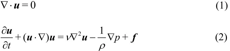
where, in 3-D,uis the velocity field,tis the time,pisthe pressure, f =(0,0,-9.81m/s2)correspondstothegravity acceleration, and arethe density and kinematicviscosity of the fluid,respectively. As a PIC based solver, the PICIN model employsboth Lagrangian particlesand an Eulerian grid.The grid is uniform and staggered following Harlow and Welch[16]and eight particles are initially seeded in each fluid cell. Following the full particle PICapproach used in Brackbill and Ruppei[4],the particles are assigned with the mass and momentum of the fluid, and are used to solve the nonlinear advection term (the second term on the left hand side of Eq.(2))and track the fluid configuration (including the free surface), while the underlying grid is solely employed for computationalconvenience for solving the nonadvection terms. During each computational cycle, the non-advection terms are first solved on the grid and then the velocity field carried by the particles and the particle position are updated using the information on the grid; more details of the solution procedure are described in what follows.It isnoted that no turbulence modelsarecurrently incorporated in the PICIN model.
The overallsolution isdivided into twomajor steps: an Eulerian step and a Lagrangian step. In the Eulerian step,theNSE,ignoring the nonlinear advection term,aresolved on thegrid using the pressureprojection technique[17],wherea pressure Poisson equation (PPE) is resolved incorporating the boundary conditions. On the free surface boundary, a second-order accurate techniquefollowing Gibou et al.[18]is employed to enforce this condition

where ζ represents the free surface position on the grid that is computed based on the particle position at each time step (see details in Chen et al.[9]). On the solid boundary, a Cartesian cut cell based approach following Ng et al.[19]is used to resolve the following conditions:
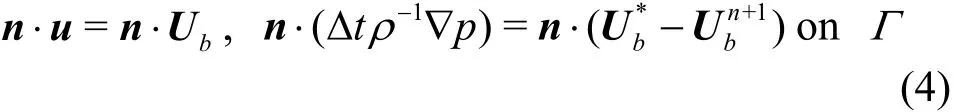
whereΓrepresents the surface of solid objects,n is the unit outward normal vector,bUis the velocity imposed on the surfaceof solid objects,the superscript +1n representsthetimestep,denotesthetentative boundary velocity before the pressureprojection step.Oncethe Eulerian stepis completed,a divergence-freevelocity fieldis obtained on thegrid.Thevelocity change,4th-order accurate weighted essentially non-oscillatory(WENO)scheme[20], toincrement the velocity field carried by the particles. It is noted that for the purpose of numerical stability,thedivergence-freevelocity itself,+1n
u ,isalsointerpolated usingtheWENO scheme to constitute a small proportion of the final velocity carried by the particles (see more details in Chen et al.[9]).After theparticlevelocity field is updated, the remaining advection term of the NSE is solved in the Lagrangian stepby advectingthe particles. That is, the particles, carrying the updated velocity field,areadvected through the divergencefreevelocity field on the grid using the3rd-order accurateRunge-Kutta scheme[21]. Once this is done,one computational cycle is completed. It is noted that at the beginning of the next computational cycle, the velocity field is mapped from the particles to the grid using a SPH-like kernel interpolation that conserves the mass and momentum (see more details in Chen et al.[10]). The current 3D PICIN model also employs the domain decomposition based MPIapproach for parallelisation[10]. For full details of the PICIN model,the reader is referred to Kelly et al.[7], Chen et al.[9,10]and Chen[22].
Thesolitary waveisgenerated usinga pistontype wavemaker approach following Wu et al.[23,24].Thisapproach adoptsthe formula of wave paddle motion proposed by Goring[25]and combines it with the9th-order solitary wave solution of Fenton[26].Specifically,with theassumption that the average horizontalwater particle velocity,adjacent tothe wavepaddle,equalsthe wavepaddlevelocity,the motion of the wave paddle is expressed by
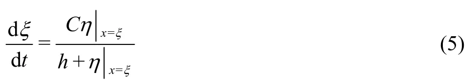
where ξis the position of the wavemaker,his the still water depth,Cis the wave celerity and is the water surface elevation. The water surface elevation at the wavemaker position isspecified according tothe9th-order solitary wavesolution of Fenton[26]
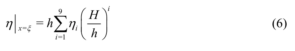
whereHisthetargeted wavecrest height of a solitary waveandiηisa function of =S sech( )KX ,
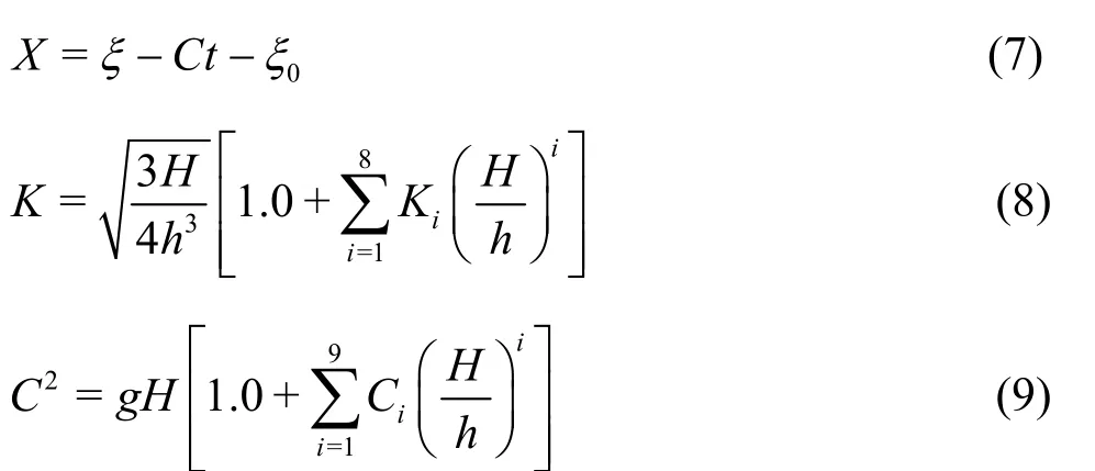
where0ξistheinitial position of thewave crest,which must be a negative value as the solitary wave is generated in a quiescent water flume,iKandiC arecoefficients, the formulas required todetermine 1η to9η,1Kto8Kand1C to9Care listed in Table 1 of Fenton[26]and are not repeated here.
In the numerical simulation,thewater surface elevation at a certain location iscomputed asthe highest position of the particles around the location in the z-direction.The waveforce on a cylinder is calculated by integrating the water pressure over the wetted area of the surface of the cylinder

2. Results and discussions
In this section, the 3-D parallel PICIN model is first validated against a benchmark test of solitary wave scattering by a single circular cylinder in terms of waveelevations around thecylinder and the horizontal wave force on the cylinder. After that, the resultsof an extension study of solitary wave interaction with a group of eleven cylinders are discussed.
2.1 Solitary wave scattering by a vertical circular cylinder
In this section, the solitary wave scattering by a single vertical circular cylinder is simulated in order tovalidate the currentnumerical model. This test casewaspreviously studied byYates andthrough both physical experiments and numerical simulations usinga GBmodel.Theexperimentsconducted byYates and used a water tank measuring 7.6 m long, 0.76 m wide and 0.6 m deep. The water depth in theexperimentswas h= 0.04m .Thesurfacepiercing vertical circular cylinder was placed on the bottom of the water tank and on the centre line of the water tank,and theradius of the cylinder was R=0.0635m . The solitary waves used in the experiment were generated by moving a flat plate which filled the tank cross section. The principal variables of interest in this test case werethewater surface elevationsin the vicinity of the cylinder and the horizontal wave loading on thecylinder. The water surfaceelevation wasmeasured in a semi-circular region around the cylinder and thelocation of the measuring point isexpressed in the polar angle θ and the radial distancer/Rmeasured from the centre of the cylinder. As examples, θ = 0orepresents the upstream centre line of the water tank and r/R=1.0 is on thesurface of the cylinder. Figure 1showsa sketch of the arrangement of the measuring points.
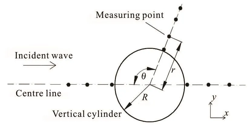
Fig.1 sketch of the arrangement of the measuring points for the water surface elevation
A numerical wave tank (NWT) was established for thepresent simulation.While thewidth of the NWT was the same as that of the water tank in the experiment, the length of the NWT was reduced to 2.0 m in order to save on CPU cost. The solitary wave was generated using the approach described in Section 1 by a piston-type wavemaker which was located at the upstream end of the NWT, and for all test cases in this section,0ξin Eq.(7)wasset to–0.5m.The cylinder was placed at the centre line of the NWT in the x-direction with the distances to the wavemaker being 1.0 m and to the downstream end of the NWT being 0.95 m, respectively. The grid size was set to Δx = Δ y= Δ z =0.0016m , resulting in approximately 1.1489×10⁸particlesand 2.986×10⁷grid cells(note that the height of the NWT was set to 0.08 m). The Courant number was set to 0.5. It took approximately 20.8h for a non-dimensional t(g/h )1/2=78.3of simulation timewith 80coresat the University of Bath High Performance Computing (HPC) system for thetest case where therelative waveheight was
Figure 2 shows snapshots of the present numerical results at various time instants for H /h = 0.4.From Fig.2 it can been seen that as the solitary wave impacts on and passes the cylinder, significant wave run-upoccurs and a smallpositive reflected wave startstopropagateradially outward (seeFigs.2(a)-2(c)).Thisreflected radial wave,asalsonoted in Yatesand Wang[11],diminishesin amplitudeasit expands and is followed by a negative wave which develops into oscillatory waves (see Figs.2(d)-(f)). It is also observed that when the main wave passes, a diffracted wave around the cylinder from the leeward side occurs,which wrapsaround thecylinder and propagates radially outward (see Figs.2(d)-(f)). This is consistent with the findings discussed in Yates and Wang[11].
Figure 3 shows comparisons of the free surface elevation along θ = 0oat different radial positions for H/h = 0.4. Note that in all comparisons of the free surface elevation (including those in Figs.4 and 5),the time was shifted consistently so that the peak wave amplitude of the numerical result coincides with that of theexperimental measurement at r/R = 4.5and θ= 0o. It can be seen from Fig.3 that generally the comparisonsshow good agreement between the present resultsand the numericaland experimental results obtained by Yates and Wang[11]. In particular,the good agreement of the main wave as shown at/=4.5rR demonstrates that thesolitary waveis correctly generated in thepresent simulation.It is neverthelessnoted that both numericalmodels over-predict the maximum wave height very close to the cylinder surface (see r/R = 1.03). We found that this is also the case for the results computed by other numerical models, e.g., Zhao et al.[12], Ai and Jin[13]and Caoand Wan[27].Thesecondary wavepeak clearly seen atr/R= 2.61andr/R= 4.5isdue to the reflected wave as observed in Fig.2.
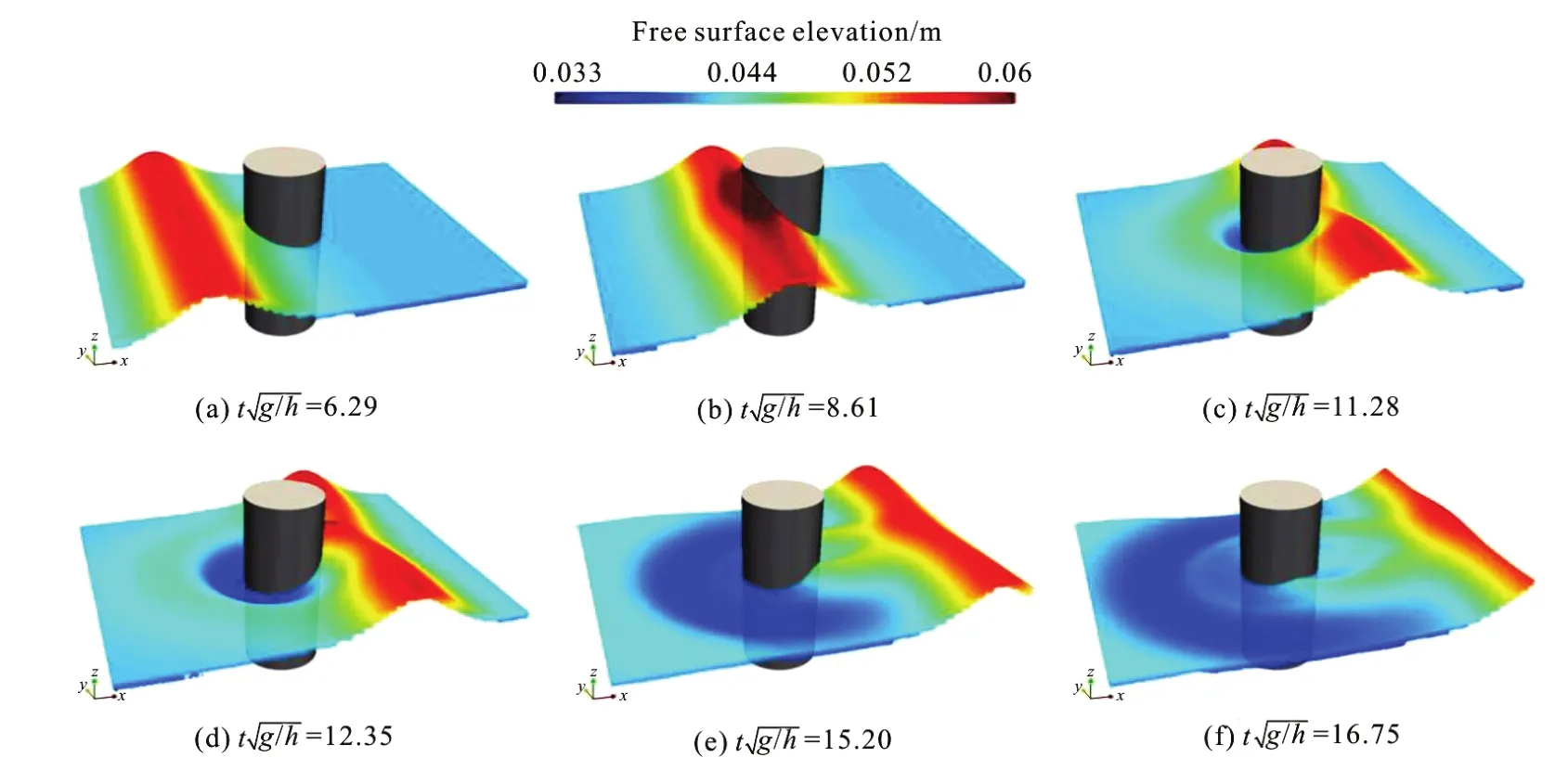
Fig.2 (Color online) Snapshots of the present numerical results for H /h=0.4
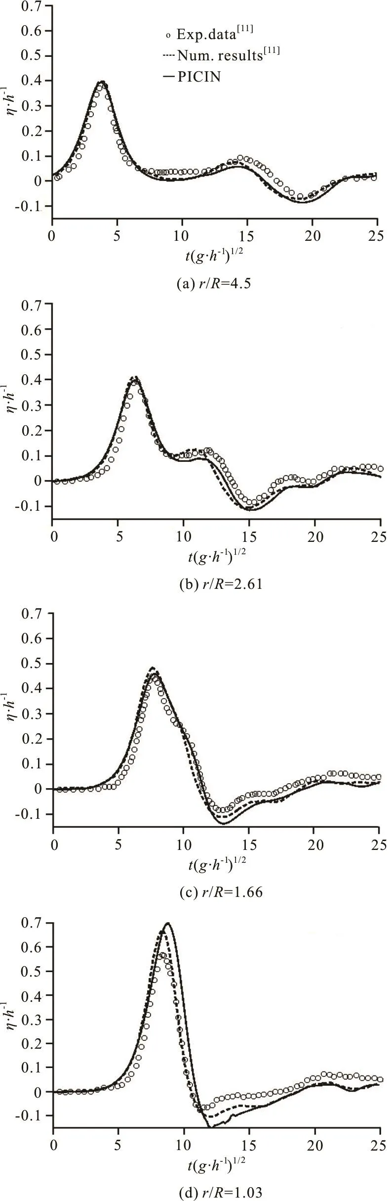
Fig.3 Com parisons of the ti me histo ries of free surfa ce elevationalongatvariousradialpositions.The numerical results are for H /h=0.4
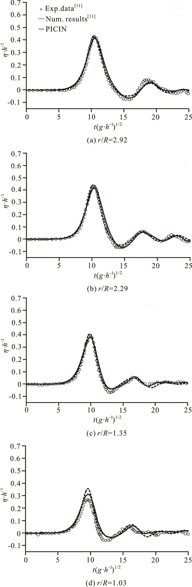
Fig.4 Comparisons of the time histories of free surface elevation along o=100 Hh θ at various radial positions. The numerical results are for /=0.4
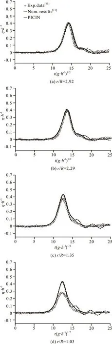
Fig.5 Comparisons of the time histories of free surface elevation along θ = 180oat various radial positions. The numerical results are for H /h=0.4

Fig.6 Comparisons of the time histories of the horizontal wave force for various incident wave heights
Figure 4 shows the comparisons of free surface elevation foro=100θ. The comparisons also show very good agreement between the present results and those obtained by Yates and Wang[11]. Both numerical models again appear to overestimate the main wave peak very close to thesurface of thecylinder (seer/R= 1.03). However, the present result seems to be slightly better thanthat of theGBmodelbyYates and The secondary wave peak asshown at all radial positionsalongθ= 100oisattributed tothe diffracted wave from the leeward side of the cylinder rather than the reflected wave. This is confirmed by Figs.2(e)and 2(f).That is,asthisdiffracted wave wraps around thecylinder and propagatesradially upstream, along theline it is first observed atr/R= 1.03 and 1.35 at around=16, and then observed at other radial points after a small time lag.
Figure 5 shows the comparisons of free surface elevation along the downstream centre lineAgain,reasonableagreement between thepresentresults and those obtainedby Yates and is shown.Notethat themain wavepeak in the experiment is significantly reduced very close to the surface of the cylinder and both the numerical models over-predict the wave amplitude. Similar resultscanalso be found in the numerical model of Zhao et
In Fig.6,comparisons of the horizontal wave force are shown for various relative wave heights. For each case, t he tim e is shift ed such tha t the p eak of the wave forceof thepresentnumericalresultcoincides with that of the experimental measurement. It can be seen from Fig.6 that for small amplitude waves (seeH/h= 24), the present numerical result agrees well with the experimental data. However, the discrepancy between thenumericaland the experimentaldata becomes larger when the wave amplitude increases. In general, the present numerical results are in reasonable agreement with the experimental measurements.
2.2Solitary wave interacting with a group of cylinders
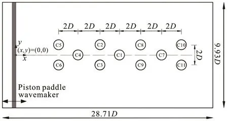
Fig.7 Sketch (plan view) showing locations of the eleven cylinders in the NWT.Dis the diameter of the cylinders
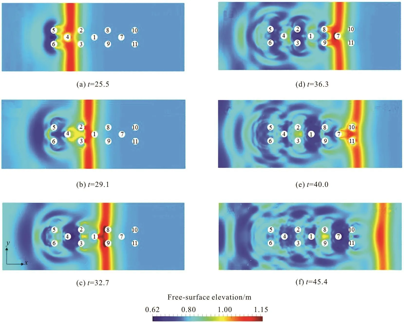
Fig.8 (Color online) Snapshots (plan view) of the numericalsimulationof a solitarywaveinteracting with a group of elevencylinders.tis the simulation time normalised by 1/2(/)hg
Thissection presents an extension study of solitary wave interaction with a group of eleven cylin-ders.The principal variablesof interest in this test case are the wave run-up,R, at the front stagnation point of each cylinder and the horizontal wave forces,F,on thecylinders.The propertiesof thesolitary wave and the layout of the cylinders used in this test case are inspired by those proposed in Mo and Liu[14].Figure7showsa sketch of thearrangement of the eleven vertical circular cylinders and the setup of the NWT. Thecylindersare labelled with C1,C2,etc.(see Fig.7) and have an identical diameter D. They aresymmetrically placed on thecentreline of the NWT, with the centre-to-centre distances being 2D between the adjacent cylinders in both the streamwise and the spanwise directions (see Fig.7). The distance in the x-direction between the centre of cylinder C1 and the wavemaker was14.7D. The length and the width of the NWT were set to28.71Dand 9.93D,respectively,and thewater depth,h,wasfixed at 0.615D. A piston-type wave paddle was employed at the upstream end of the NWT as shown in Fig.7 for solitary wave generation using the approach described in Section 1. The solitary wave used in this test case wasnon-breaking;therelative wave height /Hh was 0.4 and ξ0in Eq.(7) was set to-0 .6563D .
Thegrid size used in the numerical modelling was Δ x = Δ y = Δ z = 0.04h,resulting in approximately 8.875×10⁷particles and 3.137×10⁷grid cells (note that theheight of theNWT was set to1.64D).The Courant number was 0.5. It took approximately 14.2 h for a non-dimensional t(g/h )1/2=54of simulation time with 160 cores at the University of Bath HPC system for this demanding test case.
Figure 8 shows snapshots of the simulated wave field in plan view at different timeinstants.The solitary wave travels from left to right. Generally, it is seen that as thesolitary wave passes the cylinders,circular scattered wavesstart topropagateradially away from the cylinders, which aresimilar to what was observed in the single cylinder case presented in Section 2.1. Focusing more on detail, it can be seen from Fig.8(b)that a steepwave(maybecloseto breaking) forms in front of the cylinders C5 and C6 due tothesymmetricscattered wavesfrom both cylinders interacting with each other and propagating upstream.However,asseen from Fig.8(d),similar wavesemanating from cylindersC2and C3are blocked by cylinder C4,and thewavescould be reflected back and trapped in thecylinder group C1-C2-C3-C4. Moving to Fig.8(f), it is seen that after the solitary wave completely passes the cylinder group,a complex wave field hasformed,duetoboth wave-wave and wave-structure interaction.
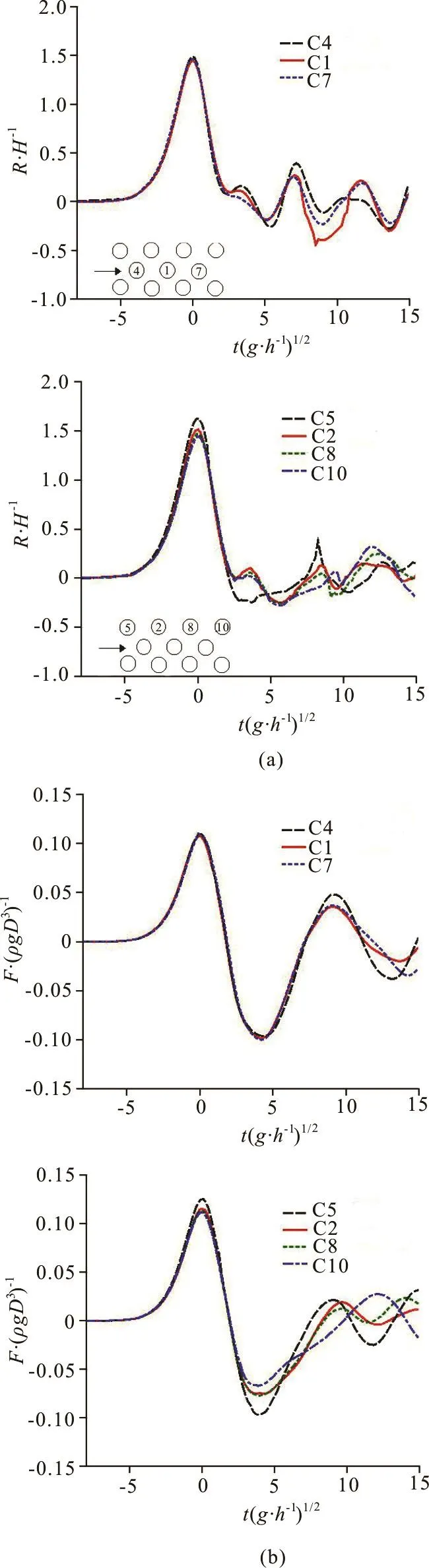
Fig.9 (Color online) Comparisons of the numerical results: (a)Wave run-up at the upstream stagnation points of different cylinders. (b) Horizontal wave forces on the cylinders
The numerical results of the wave run-upRat the upstream stagnation points of the cylinders and the wave forceFon the cylinders are plotted in Fig.9.Since theflow field is symmetrical, the resultsare presented for twocylinder groupsbased on their positions: the first group consists of cylinders C1, C4 and C7,which arelocated in themiddle,and the second group includes cylinders C2, C5, C8 and C10,which are located at the leftmost side (facing downstream). The results were all shifted in time, with the time instants of all main peak values made to coincide with the non-dimensional time zero.
Figure 9(a) shows the results for wave run-up. It can beseen that allcylindersin thefirst group(located in themiddle)exhibit very similar wave run-upfor this spatial configuration of cylinders.Similar run-up is also observed at the lateral cylinders C2, C8 and C10, with the exception of cylinder C5,which is located at the front of thecylinder group.Both the primary and the secondary peaks of the wave run-upat cylinder C5appear tobethelargest.In particular,thevery steepsecondary peak wave confirms the observations in Fig.8(b).
Figure 9(b) presents the results for the horizontal waveforceson the cylinders.It is seen that the horizontal wave forces are nearly identical on all the three middle cylinders until the secondary force peaks.These secondary peak values are approximately 38%of their corresponding primary peak values. For the forceson thelateralcylinders,cylinder C5again encountersthe largest waveforcesfor both the primary peak and theprimary trough.Apart from these,thesecondary peak forceson alllateral cylinders are very close and are nearly 20% of their corresponding primary peak forces.
3. Conclusions
Solitary wave scattering by vertical circular cylindershasbeen simulated usingthe3-Dparallel PICIN modelin this paper.The 3-DPICIN model employs the hybrid Eulerian-Lagrangian PIC method tosolve the incompressibleNSE for free-surface flowsand incorporates a Cartesian cut cellbased approach for fluid-structureinteraction.Duetothe PIC nature, both Lagrangian particles and an Eulerian grid are employed in the PICIN model, the particles carry all the material information of the fluid, and are used to track the free surface and solve the nonlinear advection term in the NSE, while the underlying grid is solely employed for computational convenience in solving the non-advection termsof theNSE.Parallelisation based on the MPI approach hasalso been implemented which enables the PICIN model to simulate large-scale 3-D problems (i.e., those require a largenumber of grid cellsand particles).The numerical model was first validated using the test case of solitary wavescattering by a singlecylinder proposed in Yates and Wang[11]. Comparisons show reasonable agreement between the present results and those (both numerical and experimental) of Yates and Wang[11].For this test case,the solitary wavewas correctly generated and the free surface elevations at various measuring points were well reproduced by the present model.Thehorizontalwaveforceson the cylinder were alsoreasonably predicted for various amplitude solitary waves. The numerical model was then used toinvestigatea solitary waveinteracting with a groupof eleven cylinders.Complexhydrodynamic processes involving violent wave-wave and wave-structure interaction tend to occur in this case.The model is capable of handling such complex 3-D scenarios.
Acknowledgements
This research was funded by the University of Bath (Graduate school funding, sponsor code: 3451)and HR Wallingford (internal research project:DDY0485).Thisresearch madeuseof theBalena High Performance Computing Service at the University of Bath. The first author gratefully thanks both institutionsfor sponsoring hisPh.D.study.DMK acknowledges the support of the IHRC at FIU.
[1]Chen L.,Sun L., Zang J. et al. Numerical study of roll motion of a 2-Dfloating structure in viscousflow [J].Journal of Hydrodynamics, 2016, 28(4): 544-563
[2]Rogers B. D., Dalrymple R. A., Stansby P. K. Simulation of caisson breakwater movement using 2-DSPH [J].Journal of Hydraulic Research, 2010, 48: 135-141.
[3] Harlow F.H.The particle-in-cellcomputing method for fluid dynamics (Alder B. Methods in computational physics)[M].New York,USA:Academic Press,1964,319-343.
[4]Brackbill J. U., Ruppel H. M. FLIP: A method for adaptively zoned, particle-in-cell calculations of fluid flows in twodimensions[J]. Journal of Computational physics,1986, 65(2): 314-343.
[5] Zhu Y. N., Bridson R. Animating sand as a fluid [J]. ACM Transactions on Graphics, 2005, 24(3): 965-972.
[6]Kelly D. M. Full particle PIC modelling of the surf and swash zones[C].Proceedings33rd International Conference on Coastal Engineering. Santander, Spain, 2012.
[7]Kelly D.M., Chen Q., Zang J. PICIN: A particle-in-cell solver for incompressible free surface flows with two-way fluid-solid coupling [J]. SIAM Journal on Scientific Computing, 2015, 37(3): B403-B424.
[8]Chen Q., Kelly D. M., Dimakopoulos A. S. et al. Validation of the PICIN solver for 2D coastal flows [J].Coastal Engineering, 2016, 112: 87-98.
[9]Chen Q., Zang J., Dimakopoulos A. S. et al. A Cartesian cut cell based two-way strong fluid-solid coupling algorithm for 2D floating bodies[J]. Journal of Fluids and Structures, 2016, 62: 252-271.
[10] Chen Q., Zang J., Kelly D. M. et al. A 3D parallel Particlein-cell solver for wave interaction with vertical cylinders[J].Under Review by Ocean Engineering, Unpublished results.
[11] Yates G. T., Wang K. H. Solitary wave scattering by a vertical cylinder: experimental study [C]. Proceedings of the Fourth(1994)International Offshore and Polar Engineering Conference. Osaka, Japan,1994, 118-124.
[12] Zhao M., Cheng L., Teng B. Numerical simulation of solitary wave scattering by a circular cylinder array [J]. Ocean Engineering, 2007, 34(3-4): 489-499.
[13] Ai C.F., Jin S. Non-hydrostatic finite volume model for non-linear waves interacting with structures[J].Computers and Fluids, 2010, 39(10): 2090-2100.
[14] Mo W. H., Liu P. L. F. Three dimensional numerical simulations for non-breaking solitary wave interacting with a group of slender vertical cylinders [J]. International Journal of Naval Architecture and Ocean Engineering, 2009,1(1): 20-28.
[15] Kagemoto H., Murai M., Fujii T. Second-order resonance among an array of two rows of vertical circular cylinders[J]. Applied Ocean Research, 2014, 47(2): 192-198.
[16] Harlow F.H., Welch J.E. Numerical calculation of timedependent viscous incompressible flow of fluid with free surface [J]. Physics of Fluids, 1965, 8(12): 2182-2189.
[17]Chorin A.J.Numerical solution of the Navier-Stokes equations[J].Mathematics of computation,1968,22:745-762.
[18] Gibou F., Fedkiw R. P., Cheng L. T. et al. A second-orderaccurate symmetric discretization of the Poisson equation on irregular domains [J]. Journal of Computational Physics, 2002, 176(1): 205-227.
[19] Ng Y.T., Min C., Gibou F. An efficient fluid-solid coupling algorithm for single-phase flows [J]. Journal of Computational Physics, 2009, 228(23): 8807-8829.
[20] Edwards E.,Bridson R. A high-order accurate particle-incell method [J]. International Journal for Numerical Methods in Engineering, 2012, 90(9): 1073-1088.
[21]Ralston A.Runge-Kutta methods with minimum error bounds[J].Mathematics of computation,1962,16(80):431-437.
[22] Chen Q. Development of a full particle PIC method for simulating nonlinear wave-structure interaction [D]. Doctoral Thesis, Bath, UK: University of Bath, 2017.
[23]Wu N. J., Tsay T. K., Chen Y. Y. Generation of stable solity wavesby a piston-type wave maker [J].Wave Motion, 2014, 51(2): 240-255.
[24] Wu N. J., HsiaoS. C., Chen H. H. et al. The study on solitary waves generated by a piston-type wave maker [J].Ocean Engineering, 2016, 117: 114-129.
[25]Goring D.G.Tsunamis–the propagation of long waves ontoa shelf [D].Doctoral Thesis,Pasadena,USA:California Institute of Technology, 1978.
[26] Fenton J. A ninth-order solution for the solitary wave [J].Journal of Fluid Mechanics, 1972, 53: 257-271.
[27] Cao H. J., Wan D. C. RANS-VOF solver for solitary wave run-upon a circular cylinder [J].ChinaOceanEngineering, 2015, 29(2): 183-196.
June 6, 2017, Revised July 24, 2017)
* Biography: Qiang Chen (1988-), Male, Ph. D.
Jun Zang, E-mail: J.Zang@bath.ac.uk
杂志排行

水动力学研究与进展 B辑的其它文章
- On the clean numerical simulation (CNS) of chaotic dynamic systems *
- BEM for wave interaction with structures and low storage accelerated methods for large scale computation *
- Flow-pipe-soil coupling mechanisms and predictions for submarine pipeline instability *
- Simulation of flows with moving contact lines on a dual-resolution Cartesian grid using a diffuse-interface immersed-boundary method *
- On the hydrodynamics of hydraulic machinery and flow control *
- A 3-D SPH model for simulating water flooding of a damaged floating structure *