In fl uence of Converter Bus Serious Harmonic Distortion on HVDC Transmission System
2017-09-11ZiyuGuoTaoLinGengtaoJiaLiyongWang
Ziyu Guo Tao Lin Gengtao Jia Liyong Wang
In fl uence of Converter Bus Serious Harmonic Distortion on HVDC Transmission System
Ziyu Guo1Tao Lin1Gengtao Jia2Liyong Wang3
Possibility of serious harmonic distortion(SHD)increases as multi-infeed direct current(MIDC)transmission develops rapidly in recent years.In this paper,the mechanism of high voltage direct current(HVDC)controller working against SHD is proposed for theoretical derivation of phase locked loop(PLL)output and valve commutation process.To reduce static error of constant extinction angle(CEA)controller and enhance active power transmission,the insertion of current error(CE)controller into CEA is mini fi ed.A calculation of inverter operating point is proposed in the end.The correctness of mechanism and algorithm is veri fi ed through power systems computer aided design(PSCAD)simulation.
High voltage direct current(HVDC),converter,harmonics,serious harmonic distortion(SHD),phase locked loop(PLL),constant extinction angle(CEA)
DOI10.16383/j.aas.2017.e160020
1 Introduction
Converter of high voltage direct current(HVDC)system turns into harmonic resource when it works with unbalanced AC voltage.Previous studies have focused on this phenomenon.According to[1],the 3rd harmonic current of inverter in international council on large electric systems(CIGRE)benchmark model can be as high as 0.469kA in unbalanced situation.However,the operation of converter working in such serious harmonic distortion(SHD)condition lacks research,for the electrical coupling between converters is usually weak in the past.With the vigorous development of multi-infeed HVDC project in China,converters may be close to each other in HVDC placement area like Shanghai and Guangzhou.Possibility of converter working in SHD keeps growing in such areas[2].Researches on converter operation in SHD are quite necessary.
Reference[3]analyzed the dynamic process of converter when asymmetrical problem happened in AC system,in which unbalanced conduction time and commutation angle between phases are considered.It calculated the harmonics generated by the converter.However,it did not elaborate the converter operation point calculation method.Reference[1]took the controller characteristic into consideration and found a way to calculate the operation point,but no further study on how other converters are a ff ected by the harmonic current is proposed.Other studies on HVDC harmonics focused mainly on the transformation of harmonic order.Reference[4]analyzed transformation of converter bus harmonics in presence of harmonic voltage.Negative correlation between the dominant harmonic amplitude and phase-change angle is certi fi ed,however,only through simulation.References[5]−[7]determined the series relationship of harmonic impedance between DC and AC sides in HVDC system by de fi ning DC and AC equivalence harmonic impedance,through which the frequency point resonance most likely to occur is calculated.However,only small signal model is applied in above references,where harmonics did not a ff ect the operation point of DC system.There is no doubt that one converter will a ff ect the control system of another by the harmonic current it generates.The operation point of the HVDC would be shifted as well.Numeric simulation software(PSCAD/EMTDC,etc.)can tell variety of DC/AC system characteristics under SHD.However,it is not enough to explain the inner theory of such phenomena.
In this paper,operation of HVDC system with SHD on converter bus is analyzed.Aiming the fact that constant extinction angle(CEA)controller cannot trace the setting value under SHD,an improved control scheme is proposed,with which steady-state error of CEA and power consumption in DC transmission are largely reduced.A calculation method of HVDC operation point in SHD is proposed in the end.The conclusion correctness is veri fi ed through PSCAD/EMTDC simulation.
2 AnalysisofConverterOperation Working in SHD
The CIGRE-benchmark model[8]applied in this paper is shown in Fig.1.Inverter side SHD is created by paralleling harmonic power source beside the inverter bus.Constant current controller(CC),CEA controller and voltage dependent current order limited(VDCOL)controller constitute the control system.

Fig.1.HVDC CIGRE-benchmark model.
According to[1]and[3],third harmonic current in AC side is the main harmonic order converter injection due to unbalanced AC voltage.Taking inverter bus voltage third harmonic as the objective,the following analysis focuses on SHD in fl uence on HVDC system,including PLL and CEA controller.HVDC control system operation characteristics in SHD are then concluded.A calculation method of HVDC operation point in SHD is proposed in the end.
2.1 Analysis of Converter Bus Waveform in SHD
The expressions of converter bus voltage,also known as point of common coupling(PCC),with harmonics are in(1)[9]
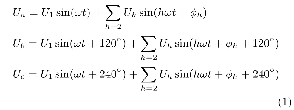
where Uhrepresents h-order harmonic amplitude while φhrepresents its initial phase.In normal operation,Uhis small with fi lter.The converter bus voltage acts as fundamental waveform.When speci fi c harmonics exceed,converter bus voltage waveform will be distorted.Taking third harmonic as example,when U1=126.81kV,U3=8.31kV,φ3=38°,the waveform of converter bus voltage of phase A and C is shown in Fig.2.Solid line represents distorted waveform while the dashed line represents fundamental waveform.

Fig.2. Voltage wave when distortion occur.
With 3rd harmonic voltage distortion,the zero crossing points of phase A and C(points where Ua=Ucin the fi gure)have shifted comparing to the normal operation status.Supposing the moments of line-to-line voltage zero crossing points when distortion happens are t1and t2,while moments of that when distortion does not happen areand.
The shift of line-to-line voltage zero crossing moment affects the actual size of extinction angle and commutation angle,which are determined by the operating characteristics of phase locked loop(PLL)in the converter fi ring angle controller.
2.2 In fl uence of Converter Bus SHD on PLL
Converter fi ring controller is a control link which achieves operating status adjustment of converter commutation device.Currently,HVDC converter normally uses PLL control system[10].The operating principle of PLL is shown in Fig.3.The inserted error in normal operation is:

where
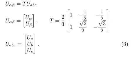

Fig.3. PLL control block.
When only fundamental wave component exists in converter bus voltage,with the above formula,inserted error can be expressed as:

In steady state,e=0 and theta completely tracks phase A voltage with angular velocity.When three phase voltage of converter bus is distorted(shown in Fig.2),inserted error e can be expressed as:

In this state,the output theta tracks two components,respectively.The angular velocity ω tracks the phase of fundamental voltage and 3ω tracks that of the third harmonic voltages.Considering that U1is much larger than U3in(5),the output of the angular velocity remains the fundamental angular velocity with small-scale fl uctuations of 2ω.The output of theta in simulation is shown in Fig.4.Fig.5 shows the output of PLL frequency when the 3rd harmonic voltage exists.

Fig.4. The output of θ by PLL.

Fig.5.Tracking frequency of PLL in SHD.
Fig.4 displays that PLL output remains unchanged in SHD.Fig.5 illustrates the small fl uctuations of Fig.4.The output component of harmonic voltage is insigni fi cant when compared with the fundamental component.In the remaining part of the paper,the impact of the commutation busdistortion on PLL output will not be considered,assuming that the PLL still locks phase-A fundamental voltage.
2.3 In fl uence of SHD on Commutation Process
The duration of some commutation process is increased by SHD,while others are decreased.This paper still uses the traditional 2-3 mode to describe this process,as is shown in Fig.6.
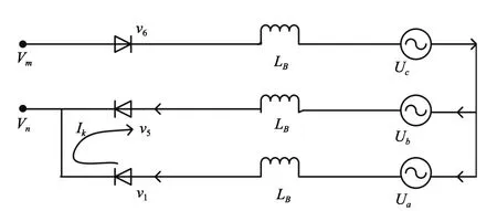
Fig.6. 2-3 mode circuit in commutation process.
In the commutation process,there is

In(6),Ikstands for the loop current rising from 0 to Id.LBstands for the commutation transformer leakage inductance.
When 3rd voltage exists only,by substituting(1)into(6),we obtain(7)

For PLL still tracks the fundamental frequency,this paper sets the fundamental frequency angle as integration length.As for phase A and C,taking 13π/6(typical starting phase angle of commutation process)as a starting point of commutation process,there is

where α stands for the fi ring angle and µ stands for commutation angle.By solving(8),we obtain(9)
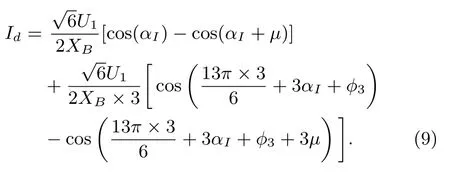
XBstands for the leakage reactance of fundamental voltage.For a more general case,when multiple SHD happens,the six commutation angles of 6-pulse inverter bridge within a cycle can be obtained by the following formula


where m=1,2,...,6.
3 In fl uence of SHD on CEA Controller
When SHD happens,there is

where Δα is the shift angle of α in SHD.
Extinction angle γ is an important indicator of the converter safe operation.Physically it means the reverse voltages time for the thyristors to fully recover its blocking capability[11].If angle γ is too small,the thyristor may bear forward voltage soon after commutation.In this case,even no new fi ring signal is given,thyristor may switch on again,resulting in a DC commutation failure.
3.1 CEA Controller Operation in SHD
CEA aims at maintaining the extinction angle for a given value[12].It is achieved by adjusting the inverter fi ring angle.The constant extinction angle controller CIGRE-benchmark model used is structured as Fig.7:

Fig.7.CEA control block.
The inverter side fi ring angle has to decrease in SHD,so as to maintain the minimum of γ per cycle to 0.2618(15°).
The active and reactive power of DC system follows(12)[13]

In(12),Eacstands for the AC bus line-to-line RMS voltage.T stands for the transformer turns ratio.B stands for the number of bridges in series.Xcstands for the commutation reactance and Vdstands for the DC voltage.By(12),the inverter side fi ring angle has to decrease in SHD,thus reducing the economic bene fi ts of DC system.
3.2 Improvements on Current Error Controller
By(12),one way to reduce the loss of transmission capacity is to minimize the decrease of inverter fi ring order.
The output of current error(CE)controller works as the interference for CEA,re fl ecting the impact of DC current on commutation process.By the switch function theory,when h order harmonic voltage distortion happens,CE will bring(h−1)order harmonic signal into CEA.This brings static error to the output of CEA,leading to the unduly reduction of the fi ring angle.
It may moderately reduce the output of CE by multiplying it with coefficient m,where m<1,in order to reduce the loss of transmission power.
4 Calculation Method of Inverter Operating Point in SHD
In AC-DC system load fl ow calculation,by using quasisteady-state model,the converter can be described as a PQ load.The only di ff erence between pure AC system and ACDC system fl ow calculation is that DC element is added to the power equation.
Under the operation of constant current controller and CEA controller,the DC current and the extinction angle remain constant,so the corresponding elements of Jacobian matrix can be easily proposed.However,commutation changes in SHD,according to(10)and(11).The inverter side extinction angle changes periodically.In this case DC quasi-steady-state model does not work well.New methods are needed to determine the operating point of the voltage distorted inverter.
Considering that the inverter side fi ring angle for fundamental voltage and power remains unchanged,(12)is able to describe the DC active and reactive power,this paper takes fi ring angle order as parameter in AC/DC fl ow calculation to get the operating point of the inverter station when distortion happens.Speci fi c procedures are in Fig.8.

Fig.8.Calculation fl owchart of HVDC operating point in SHD.
5 Veri fi cation
When SHD happens,some of the commutation angles are elongated while others are shortened.Thus the extinction angles are correspondingly shortened and elongated.The simulation result of γ by PSCAD is illustrated in Fig.8 with U1=126.81kV,U3=8.31kV, φ3=36°and α =141.69.Table I is the simulation and calculation result in one cycle. “com-valve” stands for the valves in communication process. “Cal” stands for calculation. “Sim” stands for simulation and“harm”stands for harmonic.

Fig.9. The simulation result of extinction angles per cycle.

TABLE I SiMuLAtioN AND CALCuLAtioN REsuLt oF γ PER CyCLE(°)
Figs.10−13 illustrate simulation results of the minimum of γ per cycle, fi ring angle order,power of DC transmission and fundamental line-to-ground RMS voltage of PCC respectively.SHD occurs at 2.5s.By reducing the output of CE to 20%,steady-state value of min r is reduced while fi ring angle,power transmitted and PCC voltage is increased.Table II is the result of simulation and calculation.

Fig.10. Min r in one cycle.
When SHD occurs,since the CE introduces secondary harmonic currents into CEA,the inverter side CEA cannot track reference value.By reducing the output of CE,system is still capable of stable operation,while the output of CEA can better track the reference value.Besides,the transmission power is improved to some extent.Operating point calculation conforms to simulation results,indicating that calculation method has a certain practicality.
6 Conclusion

Fig.11. Firing angle order in inverter.

Fig.12.Power of DC transmission.

Fig.13.Line-to-ground RMS voltage of PCC.
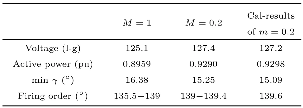
TABLE II SiMuLAtioN AND CALCuLAtioN REsuLt oF OpERAtiNG PoiNt iN SHD
The probability of SHD increases in MIDC area.In this paper,HVDC control system operation characteristics in SHD are presented.The controller’s improvement and a calculation method of HVDC operation point in SHD is proposed.Simulation results are given in the end,which match the mechanism and algorithm well,as described in the following.
1)When inverter bus SHD occurs,inverter natural commutation point shifts.PLL locks the fundamental phase in this situation,thus the sum of commutation angle and extinction angle changes.
2)SHD causes the periodic change of extinction angle.With the e ff ect of CEA,the inverter side fi ring angle order value decreases,reducing the DC line transmission capacity and economic bene fi t.By moderately reducing the output of CE,an increased power transmission capacity and improved voltage stability can be achieved.
3)Quasi-steady-state model cannot describe the operating point of inverter when SHD occurs.New calculation method by setting fi ring angle order as parameter is proposed.Simulation results demonstrate the e ff ectiveness of this method.
For future work,the operation of more power electronic elements in SHD should be considered,such as thyristor controlled series compensation(TCSC)and static VAR compensator(SVC)and the scheme will be applied to largescale power systems.
1 J.L.Liu,G.Wang,H.F.Li,Q.Zhou,and W.Zheng,“HVDC system equivalent model and harmonic calculation with dc control system characteristics taken into account,”Automat.Electr.Power Syst.,vol.38,no.19,pp.67−73,Oct.2014.
2 H.P.Zhu,L.F.Luo,and J.Z.Xu,“Harmonic instability improving mechanism in a new dc transmission system,”J.Hunan Univ.Nat.Sci.,vol.39,no.9,pp.45−50,Sep.2012.
3 Y.L.Ma,X.N.Xiao,and X.Jiang,“Analysis of the impact of ac system single-phase earth fault on HVDC,”Proc.CSEE,vol.26,no.11,pp.144−149,Jun.2006.
4 Z.Xu,“The harmonic characteristics of HVDC system under AC voltage distortion,” Electr.Power,no.2,pp.8−11,Apr.1995.
5 Y.L.Ma,X.N.Xiao,X.Jiang,and Y.Zhao,“Study on impedance-frequency characteristic of HVDC converter,”Automat.Electr.Power Syst.,vol.30,no.12,pp.66−69,91,Jun.2006.
6 Y.L.Ma,“Stability analysis of HVDC system,” Ph.D.dissertation,North China Electr.Power Univ.(Beijing),Beijing,China,2006.
7 Y.Yu,K.P.Liu,J.Chen,and Y.Zhao,“Modulation theory based criterion on composite resonant harmonic instability in HVDC transmission system,”High Voltage Eng.,vol.40,no.5,pp.1582−1588,May2014.
8 M.O.Faruque,Y.Y.Zhang,and V.Dinavahi,“Detailed modeling of CIGRE HVDC benchmark system using PSCAD/EMTDC and PSB/SIMULINK,”IEEE Trans.Power Deliv.,vol.21,no.1,pp.378−387,Jan.2006.
9 X.J.Dai,Basis of High Voltage Direct Current System.Beijing,China:Water Resources and Electric Power Press,1990.
10 Y.P.Yu,Y.Min,L.Chen,and Y.W.Zhang,“Analysis of forced power oscillation caused by continuous cyclical load disturbances,”Automat.Electr.Power Syst.,vol.34,no.6,pp.7−11,47,Mar.2010.
11 L.F.Luo,Y.Y.Lei,Y.Li,J.H.Zhang,and S.J.Deng,“E ff ects of constant arc extinguishing angle controller on HVDC transmission system,”Proc.CSU-EPSA,vol.21,no.5,pp.97−103,Oct.2009.
12 Y.Fu,L.F.Luo,Z.Tong,Y.Li,J.P.Zhou,J.Z.Xu,and F.S.Liu,“Study on voltage dependent current order limiter of HVDC transmission system´s controller,” High Voltage Eng.,vol.34,no.6,pp.1110−1114,Jun.2008.
13 C.C.Zhou and Z.Xu,“Simulation validity test of the HVDC quasi-steady-state model,”Proc.CSEE,vol.23,no.12,pp.33−36,Dec.2003.and control,power system relaying,distributed generation and micro-grid.E-mail:00008267@whu.edu.cn


Tao Lin received the B.S.E.E.,M.E.,and Ph.D.degrees from Huazhong University of Science and Technology,Wuhan,China,in 1991,1994,and 1997,respectively. He joined Central China Power Group Co,Wuhan,China,as an R&D Engineer in 1997.From May 2000 to July 2005,he was with Nagasaki University,Japan,University of Bath,U.K.,and University of Florida,USA.From 2007,he has been a full Professor at the School of Electrical Engineering,Wuhan University,Wuhan,China.His research interests include power quality,power system operation

Gengtao Jia graduated from Shanghai Jiao Tong University(SJTU),China,in 2012,he received the Ms.c.degree from University of Florida(UFL),US,in 2014.He is currently a stu ffat State Grid Shanghai Information and Telecommunication Company.His research interests include communications in electrical power networks and fi ber communication networks.E-mail:gengtao_jia@163.com

LiyongWang received the Ms.c and Ph.D.degrees from Xi’an Jiaotong University(XJTU),China in 2003 and 2007.He is currently a stu ffat State Grid Beijing Electric Power Company.His research interests include optimization of dispatching electricity market,power grid development plan and comprehensive plan.
E-mail:13810007912@163.com
Ziyu Guo,Tao Lin,Gengtao Jia,and Liyong Wang.In fl uence of converter bus serious harmonic distortion on HVDC transmission system.Acta Automatica Sinica,2017,43(8):1412−1417
the B.Eng degree of electrical engineering from Wuhan University in 2013.He has been work for Ph.D.at Wuhan University ever since.His research interests include HVDC system and its controller.Corresponding author of this paper.E-mail:15071113736@163.com
Manuscript
January 25,2016;accepted April 9,2016.
This work was supported by the National Natural Science Foundation of China(51177111)and Solar Energy Efficient Use Collaborative Innovation Center of Hubei Province.
Recommended by Associate Editor Chengdong Li.
1. Solar Energy Efficient Use Collaborative Innovation Center,School of Electrical Engineering,Wuhan University,Wuhan 430072,China 2.State Grid Shanghai Information and Telecommunication Company,Shanghai 200010,China 3.State Grid Beijing Electric Power Company,Beijing 100031,China
