Numerical analysis of bubble dynamics in the diffuser of a jet pump under variable ambient pressure*
2017-06-07XinpingLong龙新平QingqingWang王晴晴LongzhouXiao肖龙洲JunqiangZhang章君强MaosenXu徐茂森WeifengWu吴伟烽BinJi季斌
Xin-ping Long (龙新平), Qing-qing Wang (王晴晴), Long-zhou Xiao (肖龙洲), Jun-qiang Zhang (章君强), Mao-sen Xu (徐茂森), Wei-feng Wu (吴伟烽), Bin Ji (季斌)
1. State Key Laboratory of Water Resources and Hydropower Engineering Science, School of Power and Mechanical Engineering, Wuhan University, Wuhan 430072, China, Email: xplong@whu.edu.cn
2. Hubei Key Laboratory of Waterjet Theory and New Technology, Wuhan University, Wuhan 430072, China
3. School of Energy and Power, Xi’an Jiaotong University, Xi’an 710049, China
Numerical analysis of bubble dynamics in the diffuser of a jet pump under variable ambient pressure*
Xin-ping Long (龙新平)1,2, Qing-qing Wang (王晴晴)1,2, Long-zhou Xiao (肖龙洲)1,2, Jun-qiang Zhang (章君强)1,2, Mao-sen Xu (徐茂森)1,2, Wei-feng Wu (吴伟烽)3, Bin Ji (季斌)1,2
1. State Key Laboratory of Water Resources and Hydropower Engineering Science, School of Power and Mechanical Engineering, Wuhan University, Wuhan 430072, China, Email: xplong@whu.edu.cn
2. Hubei Key Laboratory of Waterjet Theory and New Technology, Wuhan University, Wuhan 430072, China
3. School of Energy and Power, Xi’an Jiaotong University, Xi’an 710049, China
2017,29(3):510-519
Recent studies have shown that the collapse of cavitation bubbles in a jet pump can generate an extremely high pressure with many potential applications. The dynamics of the bubble is governed by the Rayleigh-Plesset equation. With the bubble dynamics equation and the heat and mass transfer model solved with the Runge-Kutta fourth order adaptive step size method, the oscillations of the bubble in the diffuser of the jet pump are assessed under varied conditions. To obtain the pressure variation along the diffuser, the Bernoulli equation and the pressure measured in experiment are coupled. The results of simulation show that a transient motion of the bubbles can be obtained in the diffuser quantitatively, to obtain the pressure and temperature shock in the bubble. Moreover, increasing the outlet pressure coefficient would result in a more intense bubble collapsing process, which can be used in the subsequent studies of the cavitation applications. The predictions are compared with experiments with good agreement.
Cavitation, jet pump, bubble collapse
Introduction
The cavitation occurs in industrial structures, such as the rotating machinery, the injectors, the jet pumps, and other hydraulic devices. Most of the time,it is accompanied with serious effects like the erosion, the noise and the decrease of the fluid-machinery efficiency. However, owing to the generation of hot spots, highly reactive free radicals and turbulence associated with liquid circulation currents, in industrial applications, biological engineering[1], water disinfection[2], and even food industry, like milk sterilization, the cavitation has attracted much of attention during past several decades, and our understanding of the cavita-tion has been greatly improved. Recent reviews were made by Gogate and Kabadi[3], Luo et al.[4]and Peng and Shimizu[5].
To understand the fundamental mechanism of the cavitation phenomena[6], experiments were carried out for the growth and collapse of individual bubbles[7-12].
For numerical modeling of gas bubbles oscillating in liquids, the first analysis of cavitation and bubble dynamics was made by Rayleigh. Plesset further considered the influence of the physical characteristics of fluid viscosity and surface tension and derived the Rayleigh-Plesset equation. For many real physical problems, the shape of a bubble is unlikely to remain to be spherical, especially during the collapse phase of its motion, or when the bubble is near the boundary of the fluid. In this case, the velocity potential of the bubble motion is usually determined by the boundary element method[13].
In simulating the bubble collapse, the processing under the ambient pressure can be divided into two approaches, i.e., the constant and variable forms.
The constant pressure model is considered as able to simplify the calculation in investigating the motionof a bubble. Rayleigh, as mentioned above, took the ambient pressure as a constant. Plesset and Chapman simulated two specific cases of initially spherical bubbles collapsing near a plane solid wall, a bubble initially in contact with the wall and a bubble initially a distance of half its radius away from the wall at the closest point, with the assumption of the constant ambient pressure. Other researchers such as Popinet and Zaleski[14], Dular and Coutier-Delgosha[15]and Li et al.[16]also assume that the ambient pressure is constant in the simulation domain.
On the other hand, for bubbles under a variable ambient pressure condition, however, there is no direct, exact or accepted expression for the ambient pressure expression, p¥(t ), as a controversial issue. However, it is a crucial parameter for the mechanism of the bubble motion. Several simplified functions were suggested for the ambient pressure for convenience. A harmonic functional form is expressed as p¥= p0(1±es inw t ), where e is the amplitude of the oscillation,w is the frequency and t is the time, as suggested by Zhang and Li[17]. Furthermore, the expression for the pressure induced by the external sound field on the outside of the bubble wall,is reduced to. For small values of kR0, sin(k R0)» kR0and the pressure outside the bubble could be treated as uniform[18], whereAP is the amplitude of the acoustic wave, k is the wave number,w is the angular frequency of the acoustic wave. The equation, p¥(x,t) =p0+pasin (kx -wt + j)is employed by Wang and Manmi[19] with consideration of both the phase position and the wave velocity, where0p is the hydrostatic pressure, t is the time, and k,ap,w and j are the wave number, the pressure amplitude, the angular frequency, and the phase shift of the ultrasound, respectively. Since these pressure expressions are based neither on the measurement nor on the calculation for a real flow, the results obtained can not adequately explain the cavitation related phenomena accurately such as the thermal and pressure shock in the bubble. Qin[20]developed a numerical methodology for the calculation of the ambient pressure, i.e., the pressure distribution around the bubbles in a convergent-divergent nozzle by a CFD code, based on the RNG -ke model of the turbulent flow. In this paper, in the Ray leigh-Plesset equation, a position dependence is added, D x =v ×Dt , from the original time dependent form. Based on the above treatment of the ambient pressure, Qin et al.[21]employed a heat transfer model, including the effects of conduction plus radiation, to describe the thermodynamics of the non-condensable gas inside the bubble and the results of this heat transfer model match the previously published experimental data well. Kumar and Moholkar[22]used the approach of discrete calculations while modeling the pressure variation in the nozzle flow based on the Bernoulli equation between consecutive points. As shown in the above description, the calculation of the ambient pressure was improved by Qin and Kumar significantly. Nevertheless, the calculated ambient pressure can still not well reflect the real flow. For many cavitation applications, an accurate control of cavitation is highly desirable. For example, the milk sterilization based on the cavitation needs a high sterilization efficiency to reduce the protein inactivation. As shown in the above reviews, the ambient pressure in the simulation is still a crucial parameter, and there is no efficient method describing the pressure diffusion in a real flow.
In the present paper, the gas bubble dynamics in the liquid under the hydraulic excitation in a jet pump is numerically studied to calculate the nonlinear oscillations of the bubbles. For a thermal analysis, the heat transfer model of Qin et al.[21,23]is adopted with consideration of the energy carried by the vapor. In addition, the effect of mass diffusion is considered based on the study of Kumar and Moholkar[22]. According to our experimental results, the cavitation is induced in the outlet of the nozzle, then develops in the throat shear layer, and collapses in the diffuser finally if the cavitation number is small enough. In other word, the upstream flow of the jet pump would influence the flow in the diffuser. However, in a common diffuser, the cavitation state is absolutely different, for example, the bubble might collapse at the boundary. To sum up, the paper, considers a single bubble in the diffuser of the jet pump. The description of the ambient pressure variation is based on the pressure measured in experiment and the Bernoulli equation, which can reflect the ambient pressure variation along the diffuser in a real flow accurately. On this premise, based on the Rayleigh-Plesset equation and combined with the mass-diffusion and thermal effects, we can evaluate the pressure and temperature variations in the bubble quantitatively, which can serve as a reference for the subsequent cavitation application studies in the jet pump.
1. Mathematical formulation
In this paper, based on the concept of the confined co-axial jet cavitation, we integrate the structure of the orifice and the venturi tube with the jet pump theory. Strong vortex cavitation will be induced by using a high-speed jet to entrain the low-speed secondary flow in a confined space. This sort of confined co-axial jet cavitation is different from the traditional form of cavitation, which can induce cavitation under a relatively high environmental pressure due to the vortex in the shear layer. Moreover, the containedbubbles or cavity clouds can be conveyed downstream immediately, collapse under a high pressure, and consequently induce strong pressure shocks and thermal shocks.
Similar to the traditional central jet pump, the cavitation reactor also comprises of a nozzle, a suction chamber, a throat and a diffuser, as shown in Fig.1. The main structural parameters in Fig.1 are set as follows: Lt=96mm (the length of the throat), Dt= 16mm (the diameter of the throat), Dd=50mm (the diameter of the diffuser outlet), a=45o(the inclined angle of the suction chamber), b= 12o(the inclined angle of the diffuser) and the diameter of the nozzle outlet is 12 mm. With the above parameters, we can obtain the area ratio ()m, which is the ratio between the throat area and the nozzle outlet area and takes a value of 1.78. Besides the stainless steel suction duct and nozzle, the suction chamber, the throat and the diffuser are made of transparent Perspex material for observing the cavity cloud during the mixing process.
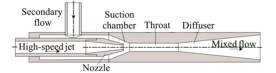
Fig.1 Schematic diagram of jet pump
Moreover, the red arrows in Fig.2 represent the mounting positions of the pressure transducers.
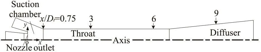
Fig.2 The positions of pressure transducers
In the experiment, the working pressure is controlled at the value of 398 kPa and various working conditions can be established by adjusting the outlet pressure. Based on the published analysis[7], the outlet pressure coefficient (Cpc) is employed to describe the dimensionless outlet pressure, which is defined as
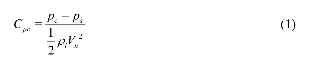
Here cp and sp are the outlet pressure and the static pressure of the secondary flow, respectively,lr is the density of the liquid andnV is the average velocity of the nozzle outlet.
1.1 Rayleigh-Plesset equation for a spherical bubble Consider a spherical bubble of radius R, as a function of the time t, in the domain of the jet pump cavitation generator. Neglecting the gravity and with the assumption of the liquid incompressibility, the generalized Rayleigh-Plesset equation for the motion of the bubble wall is[21]
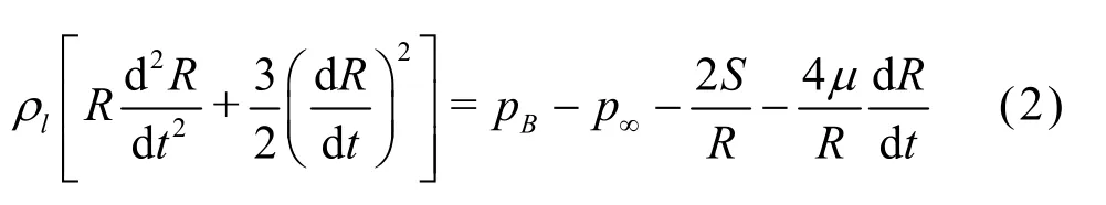
where S and m represent the surface tension and the viscosity of the liquid,Bp is the pressure inside the bubble, p¥is the ambient pressure. According to Qin et al.[21,23], the Rayleigh-Plesset equation can be modified by adding the position dependence from its original time dependent form of Eq.(2). This can be achieved by using the relationship between the velocity (v) and the displacement (x), Dx =v ×Dt , and then the position, xi, can be expressed as a function of the time t, that is,

Similarly, the ambient pressure, p¥, can be expressed as

In order to estimateBp, it is assumed[24]that a bubble contains some quantity of contaminant gas whose quality and partial pressure are0M and0gp , respectively at a certain bubble reference size0R, and some water vapor. The water vapor pressure,vp, is constant at a constant temperature, and the gas is assumed to be incondensable. With the ideal gas state equation, the following expression for the pressure in a bubble can be obtained
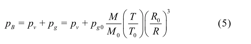
Substituting this into the Rayleigh-Plesset equation enables the numerical solution of the cavitation bubble radius with consideration of the thermodynamics.
1.2 Energy equation
According to the first law of thermodynamics, at any time interval dt, the net energy, UD , can be expressed as

where dw is the work done on the bubble, dQcond, dQconvand dQradrepresent the heat losses by conduction, convection and radiation, respectively, hvd Mvis the energy in the bubble carried by the vapor, hvdM = hvrvdV =4 p hvrvR2dR , hvis the vapor enthalpy,vr is the vapor density.
It is assumed that the bubble is spherical. At any instant of time,it, the pressure and the temperature inside the bubble areBp andBT, respectively. After a finite time step tD , the volume change of the bubble is VD . The work done on the bubble is

Assuming that the velocity of the bubble relative to the surrounding liquid is small compared to the velocity of the bubble wall during the collapse, the convection effect can be ignored. According to Qin et al.[21]and Kumar and Moholkar[22], the heat losses by conduction and radiation are expressed as

where k is the thermal conductivity of the water surrounding the bubble,thd is the distance between the two surfaces, e is the emissivity of the hot surface and kSBis the Stefan-Boltzmann constant, kSB= 5.670´10-8Wm-2K-4. When the surface of a bubble is water, the emissivity e is taken to be 0.95. A is the area of the bubble.
The net energy will raise the temperature of the gas in the bubble by TD given by[21,22]

where n is the number of moles andmixC is the specific heat of the mixed gas at constant volume. For a mixed gas,mixC can be expressed as

where,viC is the specific heat of a certain gas at a constant volume andin is the corresponding number of moles.
Substituting Eqs.(6), (7), (8) and (10) into Eq.(11), we have

1.3 Mass-diffusion equation
The mass-diffusion process across the bubbleliquid interface plays a significant role in the behavior of the gas bubbles because it may ultimately determine the presence or the absence of the bubbles in a liquid. The governing equation is
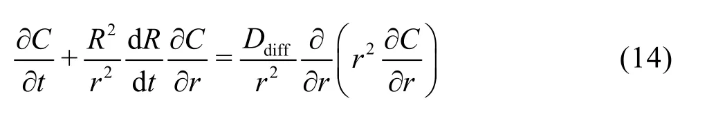
where C is the gas concentration,diffD is the coefficient of diffusion of the gas in the liquid which is determined by Eq.(15). The problem is substantially simplified as
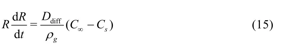
where C¥is the dissolved mass concentration at a place a large distance away from the bubble,sC is the equilibrium (or saturation) concentration of the gas in the liquid andgr is the density of the gas within the bubble. The key to these processes is provided by Henry’s law, a connection between the partial pressure of the gas acting on a liquid surface,gp, andsC

To sum up, the mass-diffusion equation in the bubble-liquid interface is

1.4 Numerical solution method
Equations (2), (13) and (17) are the complete formulation for the radial motion of the bubble with associated heat and mass transfer effects, which can besolved simultaneously using the Runge-Kutta (RK) fourth-order method, which is a kind of special high precision numerical algorithm for solving differential equation, and is widely used in engineering practice with the truncation error of O(hR4). Furthermore, although the RK method involves a larger calculation amount as compared with the methods of Euler and Heun, its precision is much higher than the other two methods in the same step length[25]. The algorithm is well described in Ref.[26].
As a higher order ordinary differential equation cannot be solved by RK directly, Eq.(2) needs to be cast into two first-order equations first, i.e.

Meanwhile, the energy equation and the massdiffusion equation are rearranged as

The calculation equation set, which contains five variables, i.e., (t, s, R, T, M), consists of four equations, Eqs.(18)-(21). In the process of calculation, we denote the time step (hR) as hR=Dt . The selection of the time step D t influences the result of the calculation greatly. Especially when the slope of the bubble radius R becomes very steep in some places, too large time step D t will increase the calculation error or even lead to numerical overflow, however, too small tD can increase the computing burden. Therefore, a variable time step length is developed to optimize the iteration process.
Based on the above considerations, a new adaptive algorithm is developed, in which the time step varies with the ratio of the bubble sizes to reduce the computing burden and at the same time ensure a high precision[27]. The details of this method are described inRef.[23].
2. Modelling of pressure variation in diffuser
To describe the ambient pressure along the diffuser accurately, Bernoulli equation is applied between the sole pressure tap (x/Dt=9.00) and any other point to obtain the ambient pressure variation. The method was described by Kumar and Moholkar[22], who divided the nozzle into 100 intervals with the assumption that the limiting case is at the throat, while the ambient pressure variation is discrete. In the present study, the continuous function of the ambient pressure can be obtained due to the fact that the flow can be obtained from the flowmeter. The velocity at the cross-section in the diffuser is calculated as

where c is dimensionless, c= x/Dt. Particularly, we denote the position of the pressure tap (x/ Dt= 9.00) as c0, then the section radius at x/Dt=9.00 can be expressed as r(c0). r(c) is expressed as

According to the Bernoulli equation with ignoring the loss of the liquid, the total pressure at an arbitrary point in the diffuser is calculated as

Combining Eqs.(22), (23) and (24), ()pc is expressed as

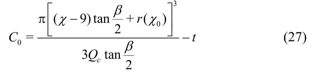
It is assumed that a bubble travels with the flow and shares the same velocity while it travels through the diffuser and the flow field is stable. The trace line of the bubble is coincident with that of the liquid, which is dc / dt= V(c). The equation of the trace line is expressed as followswhere C0is the integration constant, which depends on the location of the bubble at t =0. The collapse locations of the cavitation cloud are different under different outlet pressures, therefore the location of the bubble at t =0 is related with a specific condition.

Taking Cpc=0.234 as an example, the relevant parameters are: p(c0) =104.8 kP a, Qc=3.938L/s and V(c0) =9.02 6m/s . Substituting the above values into Eq.(25), the relation between the pressure distribution in the diffuser and the location is obtained. Moreover, with c= 7.120 (x=113.93mm)after several iterations the pressure is shown to be approximately equal to the vapor pressure of the liquid. Although the observed collapse of the cavitation cloud is located at c=7.690(x=123.00mm)approximately, there is a distinction between the location of the cavitation cloud collapse and the beginning of the process, which is closer to the upstream. In this paper, the location of the cavitation cloud collapse is assumed to be at c=7.120(x=113.93mm). Therefore, C0can be calculated by
According to the above method, we can obtain the position of the cavitation generation and0C under other conditions.

Fig.3 Comparison of radius pulsation predicted by the numerical simulation with the experimental data
3. Results and discussions
3.1 Experimental validations
In order to ensure the reliability of the simulation, the simulating result is compared with the experimental data. Figure 3 shows a comparison of the bubble radius predicted by means of the above methods with measurements by Popinet and Zaleski[28]. In the process of calculation, it is assumed that the bubble is under 100.0 kPa ambient pressure at c= 0.131 (x= 2.10 mm and the bubble contraction to the minimum radius for the first time is at the time =0t . For the first collapse (0 ms-0.4 ms), the numerical prediction fits the experimental data well. For the second collapse (0.4 ms-0.8 ms), the prediction gives a higher value. According to Zhang and Li[29], the acoustic damping mechanism is the fundamental issue for the gas bubbles oscillating in liquids. In any case, the effects of the fluid compressibility, in particular, the acoustic damping, should be taken into account. This implies that the real process of the bubble collapse is more rapid. The pulsation of the bubble cannot be depicted adequately, even with the consideration of the energy equation and the mass-transfer equation. Nevertheless, the numerical bubble collapse at the initial-time in this paper is quite accurate.
3.2 Influences of variable pressures
Using the previous analysis combined with our previous experimental data, the ambient pressure (())pc distributions along the diffuser can be obtained, as shown in Fig.4. In this figure, the ambient pressure in the diffuser increases along the x direction, while the slope of the ambient pressure decreases gradually. In addition, the higher the outlet pressure coefficient (Cpc), the higher the ambient pressure in the diffuser and the more violent the gradient of the ambient pressure. Moreover, the initial increase stage of the pressure shown in the figure is when the bubble is under a high ambient pressure. Obviously, the position of the bubble collapse and the initial increase stage of the pressure are related withpcC .

Fig.4 The ambient pressure distributions under different conditions
Under the above four conditions of ambient pressure distributions and the position of the bubble generation, the process of the bubble collapse is simulated based on the previous models. During the simulation, the parameters such as the radius variation, the pre-ssure and the temperature inside the bubble are also obtained with the assumptions that the initial radius of the bubble is 2 mm at 300 K. The variations of these parameters, may give some insight into the complicated process of the bubble collapse. The entire simulation is made with VB.net.
3.2.1 The variation of bubble radius
The simulated variations of the radii in the process of the bubble collapse under different outlet pressures are shown in Fig.5, where the bubble finishes the cycle of the collapse and starts the rebounding due to the non-equilibrium between the pressure in the bubble and the ambient pressure. However, the loss of energy and the mass diffusion of the soluble gas in the bubble result in the decaying of the bubble oscillation. The fluctuation of the bubble decays gradually until the bubble reaches the equilibrium position. By that time, the bubble is mainly filled with the soluble gas. In the experiment, it is observed that the bubble could not vanish absolutely even at the boundary of the bubble collapse but is dispersed into small bubbles, as consistent with the numerical simulation.
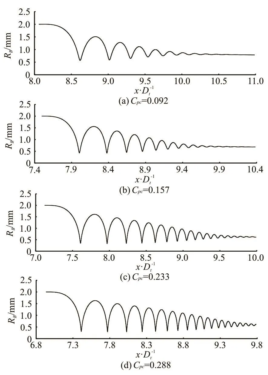
Fig.5 The variation of bubble radius under different conditions (p1=398kPa , m =1.78)
Obviously, the fluctuations of the bubble radii are similar for different outlet pressure coefficients (Cpc). However, the amplitude of the bubble pulsation and the damping rate see a great variation due to the different ambient pressures under various conditions. The effect ofpcC on the process of the first compression of the bubble in the diffuser can be seen by comparing the results of simulations for parameters in Table 1. Here D t1and D x1/Dtare the time of the first compression of the bubble and the corresponding variation of the position, RB1is the minimum size of the bubble, RB1/RB0is the ratio between the minimum and the initial sizes of the bubble. Dt1and Dx1/Dtare decreased to 0.462 ms and 0.476 from 0.813 ms and 0.557, respectively with the increase of pcC from 0.092 to 0.228. Apparently, a smallerpcC leads to a larger velocity of the bubble travelling to downstream. On the one hand, increasingpcC leads to a more intense increase of the pressure on the collapse boundary and a larger ambient pressure. On the other hand, the velocity of the bubble to downstream is larger due to a smaller cross section area on the collapse boundary and the ratio betweenBR and t is larger in view of Eq.(20). Therefore, increasing the outlet pressure coefficient, the vibration of the bubble in both space and time domains will be more intense and the pulsation amplitude of the bubble radius will increase significantly.

Table 1 Comparison of parameters at the first compression of the bubble
In addition, increasing Cpcleads to a smaller damping velocity of the bubble radius. For the pulse amplitude of the bubble radius to decrease to 0.25 mm at Cpc=0.092, it will take the bubble 5 pulse processes as shown in Fig.5(a). However, it takes the bubble 14 pulse processes at Cpc=0.288to achieve the same amplitude as shown in Fig.5(d). It demonstrates that a higherpcC will lead to a smaller oscillation damping. Since improvingpcC will increase the ambient pressure for the bubble and increase the pressure difference inside and outside of the bubble, which accounts for more energy for the bubble fluctuation. It demonstrates that increasingpcC leads to a smaller mass diffusion in the bubble motion. According to themass diffusion, the difference (C¥- CS) diminishes and one may have a stable equilibrium. Absolutely, the larger Cpcresults in a smaller decrease of (C¥- CS), therefore, it will take more oscillations to reach the equilibrium state.
During the process of the bubble collapse in the simulation, one sees a violent oscillation and it decays gradually, while the real pressure of the cavitation flow is not homogeneous, as a result, the randomness due to the interactions between the bubbles will be enhanced. In addition, the bubble may generate centripetal explosions breaking small bubbles at the first compression of the bubble. It is of engineering significance investigating the pressure and temperature shock in the process of a bubble collapse. How to obtain an appropriate pressure and temperature shock is also an important part of the study for the cavitation applications. Therefore, the following two sections will address the pressure and temperature shock resulted from the process of the bubble collapse.
3.2.2 Pressure shock
In the above section, the bubble is simulated by using the conduction plus radiation model and the mass-diffusion equation. During the simulation, other parameters such as the pressure and the temperature inside the bubble in the bubble dynamics equation are also obtained.
In this section, we will discuss the oscillation of the pressure in the bubble, as shown in Figure 6, under various outlet pressures corresponding to the radius variations shown in Fig.5. Obviously, when the bubble is under a high environmental pressure, the bubble radius fluctuates drastically accompanied with a strong pressure shock. When the radius of the bubble is reduced to its minimum size, the pressure in the bubble is increased to its maximum value. The pressure shock reaches up to 0.259 MPa, which is much higher than the ambient pressure, at the first compression of the bubble when Cpc=0.092, however, the maximal amplitude decreases to 0.221 MPa at the second compression as shown in Fig.6(a). It demonstrates that the pressure pulsation will decay constantly with the bubble traveling to the downstream, and eventually, the pressure in the bubble will slightly fluctuate around the environmental pressure. In Fig.6(a), when the bubble transfers to the place x/ Dt=10.5, the pressure in the bubble is approximately the environmental pressure, which is 58.1kPa, and the pulsation is weak.
As the process of the pressure shock is synchronous with the pulsation of the bubble radius, namely, with the compression of the bubble, the pressure in the bubble increases violently and when the bubble expands, the pressure decreases dramatically. Therefore, whenpcC increases, the time interval between the pressure shocks is shrunk and the velocity of the amplitude decaying is smaller. Figure 6 demonstrates that the oscillating amplitude is of the order of 0.1 MPa when the bubble is under three pressure shocks at Cpc=0.092. And it would take the bubble seven pressure shocks to achieve the above results at Cpc= 0.157. Similar to the variation of the bubble radius, a larger Cpcresults in a smaller decrease of (C¥- CS), then it takes more pressure shocks to reach the equilibrium state.

Fig.6 The variation of pressure under various conditions (1=p 398kPa, =1.78m )
Moreover, the amplitude is increased apparently with the increase of Cpc. As shown in Fig.6, when Cpc=0.092, 0.157, 0.233 and 0.288, the maximum values of the pressures are 0.157 MPa, 0.932 MPa, 2.929 MPa and 5.312 MPa, respectively. However, unlike Figs.6(a) and 6(b), the maximums of the pressure amplitudes are not observed at the first pressure shock but at the second one in Figs.6(c) and 6(d). This suggests that not only the increase of the initial-time pressure but also the ambient pressure impacts the amplitude of the pressure shock. For Figs.6(c) and 6(d), the bubble is under a larger ambient pressure when travelling to the position of the second pressure shock, which results in a higher pressure amplitude (the maxi-mum one). Nevertheless, the amplitudes at the first pressure shock in Figs.6(c) and 6(d) are still larger than the previous two. In other words, increasingpcC leads to a more intense pressure shock.
3.2.3 Temperature shock
Figure 7 shows the variations of the temperature in the bubble under various conditions, which is similar to the variation of the pressure shown in Fig.6. The temperature shock occurs when the bubble collapses to its minimum size. As the bubble travels to downstream and the pulsation of the bubble weakens, the amplitude of the temperature shock decays. Eventually, the temperature fluctuates around the environment temperature.

Fig.7 The variation of temperature under various conditions (p1=398kPa , m =1.78)
We can deduce from Fig.7 that a larger Cpcleads to a higher temperature shock. As shown in Figure 7(a), the maximum temperature is 494.9 K at Cpc=0.092, however, the maximum temperatures are 768.1 K and 1117.1 K at Cpc=0.157 and 0.233, respectively. Particularly, when Cpcincreases to 0.288, the maximum temperature is 1368.1 K during the process of the bubble contraction. Similar to the pressure shock, when Cpcincreases, the time interval between the temperature shocks is shrunk and the velocity of the amplitude decaying is smaller. As shown in Fig.7, the oscillating amplitude is of the order of 400 K when the bubble is under three temperature shocks at Cpc= 0.092. It takes the bubble ten temperature shocks to achieve the above results at Cpc=0.288. Therefore, Cpccan increase not only the intensity of the pressure shock but also the temperature shock. The increase of the pressure difference inside and outside of the bubble drives the liquid do more work on the bubble during the bubble contraction. Moreover, more energies are transformed into the internal energy of the bubble with the increase of the temperature.
In addition, the maximums of the temperature amplitudes are not observed at the first temperature shock but at the second one in Figs.7(c) and 7(d), similar to the pressure shock. This proves again that not only the increase of the initial-time pressure but also the ambient pressure impacts the bubble fluctuation.
4. Conclusions
The present work simulates the bubble collapse based on the Rayleigh-Plesset equation, which includes the thermal and mass diffusion. Moreover, the variation of the ambient pressure is calculated based on the Bernoulli equation combined with the experiment measurements. The results of the simulation show that a transient motion of the bubbles can be obtained in the diffuser, giving rise to the radial formation in the bubble to induce the pressure and temperature effects. The results can be a reference for subsequent studies of cavitation applications in the jet pump. In addition, due to the simple flow geometry of the jet pump, such a system is very easy to design and scale up for large-scale applications. By manipulating the outlet pressure of the flow, one can very easily control the intensity of the cavitation. In summary, the following conclusions are drawn.
(1) When the bubble is under a high ambient pressure, the bubble radius fluctuates drastically accompanied with a strong pressure and temperature shock. Due to the dissipation of the energy and the diffusion of the contaminant gas, the oscillation of the bubble decays gradually until the bubble radius slightly fluctuating around a constant value. At this time, the main content of the bubble is the contaminant gas.
(2) The amplitudes of the temperature and the pressure are decided by two factors: the velocity of the ambient pressure increase at the initial time and the value of the whole ambient pressure.
(3) Moreover, increasing the outlet pressure coefficient leads to a more intense bubble collapsing process, where the amplitudes of the pressure and tempe-rature shock increase significantly and the time interval decreases between the adjacent shocks.
[1] Balasundaram B., Pandit A. Selective release of invertase by hydrodynamic cavitation [J]. Biochemical Engineering Journal, 2001, 8(3): 251-256.
[2] Gogate P. R. Cavitation: An auxiliary technique in wastewater treatment schemes [J]. Advances in Environmental Research, 2002, 6(3): 335-358.
[3] Gogate P. R., Kabadi A. M. A review of applications of cavitation in biochemical engineering/biotechnology [J]. Biochemical Engineering Journal, 2009, 44(1): 60-72.
[4] Luo X. W., Ji B., Tsujimoto Y. A review of cavitation in hydraulic machinery [J]. Journal of Hydrodynamics, 2016, 28(3): 335-358.
[5] Peng G., Shimizu S. Progress in numerical simulation of cavitating water jets [J]. Journal of Hydrodynamics, 2013, 25(4): 502-509.
[6] Ji B., Wang J., Luo X. et al. Numerical simulation of cavitation surge and vortical flows in a diffuser with swirling flow [J]. Journal of Mechanical Science and Technology, 2016, 30(6): 2507-2514.
[7] Xiao L., Long X. Cavitating flow in annular jet pumps [J]. International Journal of Multiphase Flow, 2015, 71: 116-132.
[8] Zhang A. M., Cui P., Cui J. et al. Experimental study on bubble dynamics subject to buoyancy [J]. Journal of Fluid Mechanics, 2015, 776: 137-160.
[9] Zhang A. M., Wang S. P., Huang C. et al. Influences of initial and boundary conditions on underwater explosion bubble dynamics [J]. European Journal of Mechanics. B, Fluids, 2013, 42(2): 69-91.
[10] Long X., Zhang J., Wang Q. et al. Experimental investigation on the performance of jet pump cavitation reactor at different area ratios [J]. Experimental Thermal and Fluid Science, 2016, 78: 309-321.
[11] Xiao L., Long X., Zhang J. Shear cavitation in an annular jet pump under recirculation conditions [J]. Journal of Fluids Engineering, 2016, 138(6): 061303.
[12] Peng X. X., Ji B., Cao Y. et al. Combined experimental observation and numerical simulation of the cloud cavitation with U-type flow structures on hydrofoils [J]. International Journal of Multiphase Flow, 2016, 79: 10-22.
[13] Zhang A. M., Li S., Cui J. Study on splitting of a toroidal bubble near a rigid boundary [J]. Physics of Fluids, 2015, 27(6): 062102.
[14] Popinet S., Zaleski S. Bubble collapse near a solid boundary: A numerical study of the influence of viscosity [J]. Journal of Fluid Mechanics, 2002, 464: 137-163.
[15] Dular M., Coutier-Delgosha O. Thermodynamic effects during growth and collapse of a single cavitation bubble [J]. Journal of Fluid Mechanics, 2013, 736: 44-66.
[16] Li B. B., Zhang H. C., Lu J. et al. Experimental investigation of the effect of ambient pressure on laser-induced bubble dynamics [J]. Optics and Laser Technology, 2011, 43(8): 1499-1503.
[17] Zhang Y., Li S. Mass transfer during radial oscillations of gas bubbles in viscoelastic mediums under acoustic excitation [J]. International Journal of Heat and Mass Transfer, 2014, 69(2): 106-116.
[18] Zhang Y., Du X. Influences of non-uniform pressure field outside bubbles on the propagation of acoustic waves in dilute bubbly liquids [J]. Ultrasonics Sonochemistry, 2015, 26: 119-127.
[19] Wang Q. X., Manmi K. Three dimensional microbubble dynamics near a wall subject to high intensity ultrasound [J]. Physics of Fluids, 2014, 26(3): 132-143.
[20] Qin Z. Investigation of the cavitation mechanism and erosion of submerged high pressure water jets [D]. Doctoral Thesis, Brisbane, Australia: The University of Queensland, 2004.
[21] Qin Z., Bremhorst K., Alehossein H. Simulation of cavitation bubbles in a convergent-divergent nozzle water jet [J]. Journal of Fluid Mechanics, 2007, 573: 1-25.
[22] Kumar K. S., Moholkar V. S. Conceptual design of a novel hydrodynamic cavitation reactor [J]. Chemical Engineering Science, 2007, 62(10): 2698-2711.
[23] Alehossein H., Qin Z. Numerical analysis of Rayleigh-Plesset equation for cavitating water jets [J]. International Journal for Numerical Methods in Engineering, 2007, 72(7): 780-807.
[24] Franc J. P., Michel J. M. Fundamentals of cavitation [J]. Fluid Mechanics and Its Applications, 2005, 76(11): 1-46. [25] Yang W. Y., Cao W., Chung T. S. Applied numerical methods using MATLAB [M]. New York, USA: Wiley, 2005.
[26] Mathews J. H., Fink K. D. Numerical methods using Matlab [M]. 3rd Edition, Ney Jersey, USA: Pertince-Hall Inc, 2004.
[27] Kiusalaas J. Numerical methods in engineering with Python [J]. Special Issueon Proceedings of Siggraph, 2010, 29(2): 4183-4209.
[28] Popinet S., Zaleski S. Bubble collapse near a solid boundary: A numerical study of the influence of viscosity [J]. Journal of Fluid Mechanics, 2002, 464: 137-163.
[29] Zhang Y. N., Li S. Improved formulas for thermal behavior of oscillating nanobubbles [J]. Journal of Hydrodynamics, 2016, 28(2): 325-328.
10.1016/S1001-6058(16)60763-1
October 22, 2015, Revised September 6, 2016)
* Project supported by the National Natural Science Foundation of China (Grant Nos. 11472197, 51679169 and 51109174), the Fundamental Research Funds for the Central Universities (Grant No. 2042016gf0032).
Biography:Xin-ping Long (1967-), Male, Ph. D., Professor
Bin Ji, E-mail: jibin@whu.edu.cn
猜你喜欢
杂志排行

水动力学研究与进展 B辑的其它文章
- Standing wave at dropshaft inlets*
- Shedding frequency of sheet cavitation around axisymmetric body at small angles of attack*
- Shock waves and water wing in slit-type energy dissipaters*
- Optimal contract wall for desired orientation of fibers and its effect on flow behavior*
- Numerical investigation of the time-resolved bubble cluster dynamics by using the interface capturing method of multiphase flow approach*
- The influence of nonlinear shear stress on partially averaged Navier-Stokes (PANS) method*