Computationalanalysis of the flow ofpseudoplastic power-law fluids in a microchannel plate
2017-06-01SaeedMortazavi
Saeed Mortazavi
Department of Chemical Engineering,Shahrood Branch,Islamic Azad University,Shahrood,Iran
1.Introduction
Rapid growth of microsystems technologies in recent years leads to use of these systems for various applications.These applications vary from chemical to biological fields such as microheat exchangers[1,2],electrodes[3],microelectromechanical systems[4],fuel cells,microreactors[5,6],molecular biology[7-9],DNA chips[10],selective extraction[11],multiphase emulsions preparation[12],hollow sphere production[13]and many other technologies.High surface-volume ratio and small scale dimensions lead to microdevices advantage over conventional macrosystems.For optimum design of microsystems,it is necessary to recognize the transport phenomena in the microscale.Unfortunately,the small dimensions of these devices cause some problems when high flow rates are needed.At large input the flow velocity is very high which results to huge pressure drop and non-uniformity in flow distribution and reduces the microchannels performance.Therefore,many numerical and experimental studies were performed to investigate the flow behavior and heat transfer in the microchannels.
Some experiments were performed to study the velocity distribution through the microchannels.Adeosunet al.[14]characterized experimentally and numerically the mixing performance of a T-junction microchannel.Residence time distribution(RTD)was used to indirectly assess the mixing behavior in the microchannel.The results showed good agreement between normalized RTD results(obtainedviaconvection-diffusion model)and normalized experimental RTDs.Joneset al.[15]studied the flow distribution in a 76-channel heat sink microchannel using an infrared microparticle image velocimetry(IR μPIV)technique.It was observed that the misdistribution for low Reynolds number was very low.
A few studies investigated the pressure drops along the microchannels.Zivkovicetal.[16]developed a correlation equation forpressure drop along a rectangular orifice within a similar shaped channel under creeping flow situations.Their correlation implies that the pressure drop is appropriate to the average velocity through the orifice.However,this approximation was valid only for orifice aspect ratio greater than 30.
There are some works on the power-law fluids flow in the channels.Srinivas[17]investigated a 2D electro-osmotic flow of a power-law fluid within circular and elliptic microchannels.Their results showed that the elliptic microchannels decrease the flow rate as compared to the circular ones.Zhuet al.[18]studied the periodical flow of the power-law fluids through a rectangular microchannel while electroviscous affected the flow pattern.It was concluded that the velocity field depends mostly on the flow index parameter(n).Stockset al.[19]optimized heat transfer ability of non-Newtonian fluid flow in a simple and complex microchannel.A shear thickening non-Newtonian fluid(dilatants)with flow index ofn=1.5 greatly reduced the thermal conductivity and thus heat transfer efficiency.BIJJAMetal.[20]studied a 2-D flow of power-law fluids over a circular cylinder confined in a channel for a varying range of power-law indices and Reynolds numbers.They elucidated that for highly shear thinning fluids(n≤0.6),the total drag coefficient increases with increasing value of Reynolds number.However,for power-law fluids(n>0.6)the drag coefficient decreases on increasing the Reynolds number.Mohebbiet al.[21]studied the laminar power-law fluid flow(with power-law flow indices ofn=0.7 andn=1.3)between two parallel plates for different Reynolds numbers.Their results showed that the heat transfer rate increases with an increase in the power-law index.Hayatet al.[22]presented the peristaltic motion of power-law fluids in an asymmetric channel with convective conditions at the channel walls.Their thermal studies revealed that increase in the power-law fluid parameter decreases the temperature of fluid.Shojaeianet al.[23]performed convective heat transfer analysis to reveal the effect of some variables such as powerlaw flow indexes on the heat transfer characteristics of fully developed power-law fluid flows in tubes underuniform heat flux.They concluded that Nusselt number decreases with increasing power-law index.Yigitetal.[24]investigated numerically the effects ofaspectratio on the laminar Rayleigh-Bénard convection of the power-law fluids in rectangular enclosures with differentially heated horizontal walls.They found that the mean Nusselt number does not exhibit a monotonic increase with decreasing power-law index for aspect ratios smaller than 2 due to change in the flow pattern.Baranwal and Chhabra[25]studied the effects of the power-law index on the streamlines and Nusselt numbers along the surface of the hot and cold cylinders.They showed that heat transfer is enhanced in shear thinning fluids.Akbar and Butt[26]investigated peristaltic mechanisms in a two dimensional nonuniform channel filled with Herschel-Bulkley fluids.They observed that the flow velocity decreases with an increase in power-law index.Dhiman and Kumar[27]studied the flow of non-Newtonian power-law fluids over a triangular cylinder confined in a planar channel.They reported that for a fixed value of the Reynolds number,friction component of drag coefficient and pressure component of drag coefficient decreases with decrease in power-law index.Sun and Zhang[28]studied numerically a non-Newtonian nanofluid in a microplanar sudden expansion.They indicated that there exists a huge overestimate on the system pressure drop if Newtonian model is taken instead of non-Newtonian model.Nikfarjam and Sohankar[29]investigated power-law fluid flow from a single and two tandem square cylinders in the laminar fluid flow regimes.They showed that the pressure and total drag coefficients of the upstream cylinder decrease slightly and then increase with the power-law index.Tianet al.[30]prepared two shear thinning fluids from xanthan gum(XG)and propylene oxide solutions under alkaline condition.Their measurements showed that these two fluids can reduce the pressure drop of straight pipe.Raoet al.[31]described the flow and heat transfer from a square cylinder immersed in power-law fluids.They found that the effect of power-law index on both the pressure drag and heat transfer coefficients diminishes with the increasing in the Reynolds number.Bhartiet al.[32]investigated the pressure drop of incompressible power-law fluids through a cylindrical microchannel at low Reynolds number.They showed that the pressure drop increases with increasing shear-thinning behavior.Borzenkoet al.[33]simulated numerically the axisymmetric power-law fluid flow in a pipe with a sudden contraction.They showed that the local resistance coefficient increases with increase in the power-law index.Dosunmu and Shah[34]investigated the laminar flow behavior of non-Newtonian fluids using Carreau and modified power-law models and derived a new flow rate-pressure drop equation.Babaieet al.[35]presented an empirical correlation between friction pressure and generalized Reynolds number for annular flow of power-law fluids.Liet al.[36]investigated the three dimensional laminar flow and forced convective heat transfer of carboxy methyl cellulose aqueous solutions as shear-thinning power-law fluids in protruded microchannel.They proposed a new correlation which considers the effect of the power-law index on the relative friction factor and Nusselt number.
The effect of microchannels structure on the flow pattern was also investigated.Meiet al.investigated the flow distribution in an A-type(with one inlet and two outlets)microchannel reactor for hydrogen production[37].Their results showed that the standard deviation of the velocity flow field in the A-type microreactor was about a third of that Z-type microreactor.Balajiet al.designed a novel microchannel plate configuration to obtain uniform flow distribution athigh velocities[38].Their results showed that the microchannels with one inlet and two outlet ports in line with the microchannels lead to more uniform flow distribution than other configuration.However this work restricted to Newtonian fluids.
Most of the above studies were focused on the flow behavior or heat transfer coefficients of microchannels and more generally restricted to Newtonian fluids.The pressure drop optimization through microchannels was less considered.On the other hand non-Newtonian fluids and especially pseudoplastic fluids have extraordinary potential for lowering pressure drop of the flows and thus reduction of energy consumption as their viscosity reducing with increase in shear rate.Therefore,the main object of the present study is numerically study the pressure drop of power-law fluids through a microchannel plate.The configuration of this microchannel was optimized previously with Balajiet al.[38].In addition,the flow distributions through the whole of the microchannel,flow pattern in each slit and along outlets ports were investigated.Also,the heat transfer of the power-law fluids through the microchannel with various configurations and in a wide range of Reynolds number was investigated.The power-law fluids with various flow indexes(n)and different operating conditions were considered here.
2.Governing Equations
The geometry of the microchannel is similar to that described by Balajet al.[38].Brie fly,a rectangular microchannel plate with dimensions of 8.6 mm×7 mm and with different channel numbers was considered here.The widths of plates between channels were set to 0.2 mm.Fig.1 shows the 2-D view of microchannel geometry with delineated centerline,flow directions,channel passages,inlet and outlets arcs.The inlet and outlet ports had circular shape which showed that have better performance than other geometrical shapes.One inlet and two outlets in the figure are linked to one microplate and the other three voids are related to another microplate(as a possible counter-current microheat exchanger)which were considered here as solid bodies.
Three main continuity,momentum and energy equations in 2-D Cartesian coordinates were solved for the entire geometry:

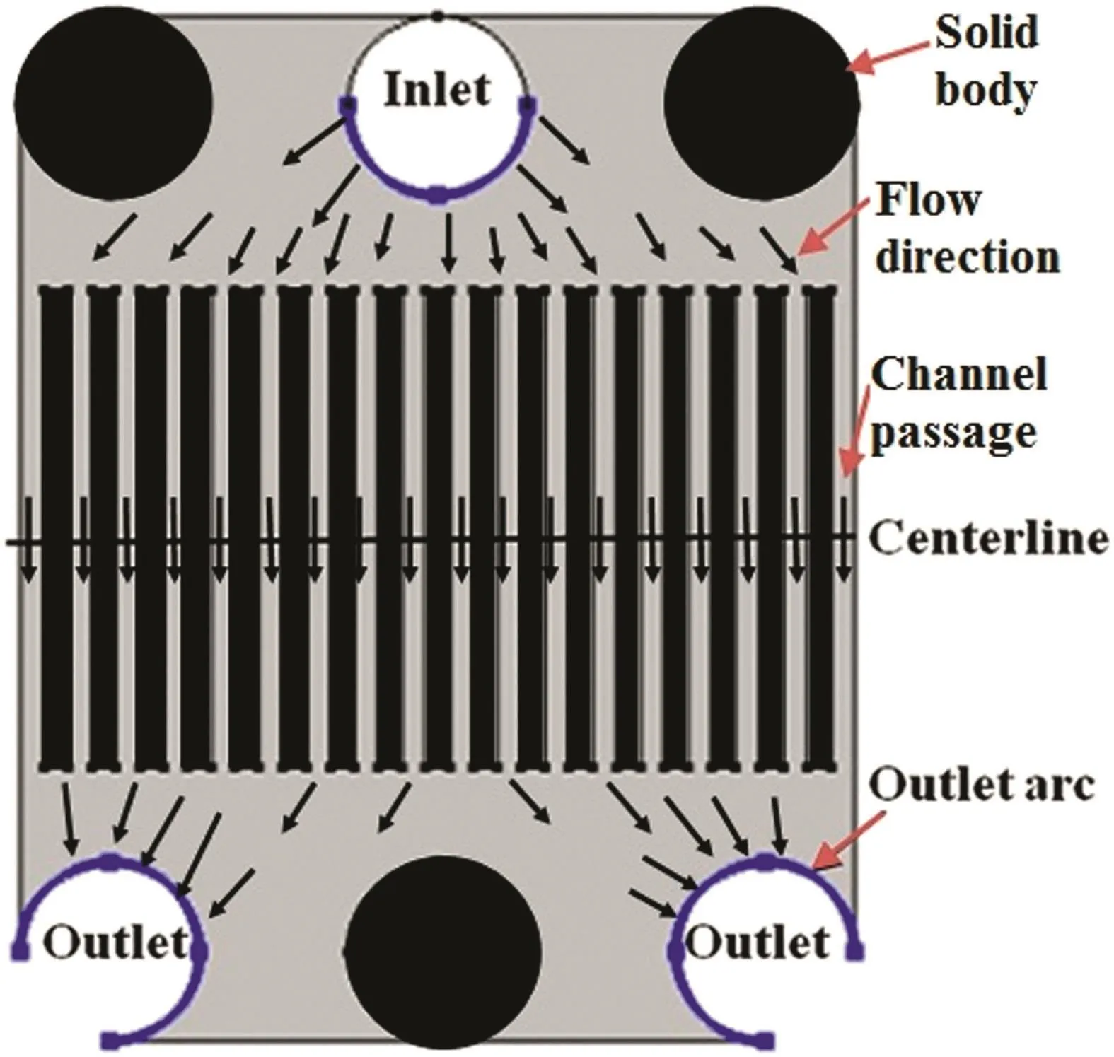
Fig.1.Microchannel geometry with defined centerline,inlet and outlet arcs.

where U,I,p,T,ρ,Cpandk′are the velocity vector,identity tensor,pressure,temperature, fluid density(1000 kg·m-3),heat capacity(4182 J·kg-1·°C)and heat conductivity coefficient(0.6 W·m-1·°C),respectively.τ is the stress tensor for the power-law fluids:

whereK,nand γ˙are consistent coefficient, flow index and the flow shear rate,respectively.The fluid was supposed to be incompressible and thus its density was remained constant.The inlet velocity(u0)was set to constant values.High velocity values were chosen to assess the flow distribution through the microchannel,while the laminar flow regime situation was satisfied.The pressure at the outlet was zero.No slip boundary conditions(zero velocity)at the microchannel walls were specified.The inlet fluid and wall temperatures were set to 290 K and 320 K,respectively.
The Darcy friction factor and Nusselt number are defined as follows:

whereD,Landhare the characteristic length of geometry(the width of the slits),the microchannel length and the heat transfer coefficient,respectively.The modified Reynolds numberfor power-law fluids is[39]:

Since the main differences between constitutive equations of powerlaw and Newtonian fluids are the non-unity flow index of power-law fluids,this study focused mainly on this parameter.Therefore the flow indexes varied from0.4 to 1,because the power-law fluids were considered as pseudoplastic(except forn=1 which was related to Newtonian fluid).The values ofKwere chosen such that the modified Reynolds number was below 1000.The choice of low values of flow indexes or consistent coefficient leads to very high Reynolds numbers(at constant velocities)and changes the flow regime from laminar to turbulent one.
Non-uniform triangular mesh elements were used for the flow domains.Mesh resolution was fine and intensified close to the wall and near the outlet arcs.To assess the effect of grid size parameter on the solution accuracy,the mesh resolution increased until the error between two refinement steps was lower than 1%.Fig.2 shows the effect of grid size on the pressure and average velocity in the middle slit.When grid size was smaller than 0.05 mm,the solutions were considered as independent of grid size.Similar procedures were performed for other fluids.The convergence criteria for residuals were set to 10-4as it is an accepted value for most numerical simulations[40].The simulations were performed with 110866 elements and 176448 degree of freedom using finite element method.
In addition,for investigation of the validity and certitude of the numerical procedure,a primary simulation was performed based on the work of Balajet al.with their microchannel configuration and fluids characteristics[38].The average velocity at the middle slit was chosen as criterion variable and the Reynolds number was varied from 5 to 200.Fig.3 shows the comparison between our results and their data.As can be seen there is good agreement between the two results.
3.Results and Discussion
3.1.Velocity distribution along the microchannel plate
Fig.4 shows the surface plot of velocity in the microchannel plate.The velocity is higher at the inlet ports and decreases through the microchannel.Although the flow velocity near the walls is very low.It seems that the flow near these regions is very prone to be stagnant.The main difference between the velocity profiles of different powerlaw fluids is at the out of slits.For low power-law index,the flow streams don't admix near the slits in contrast with Newtonian fluid where the flow is more homogeneous.The viscosity dependence of power-law fluids to shear rate causes their velocity profiles are more sensible to sudden expansion[28].
Fig.5 shows the velocity distribution along the microchannel slits of power-law fluids with different flow indexes(n).The profiles relate to the centerline halfway of the microchannel plate(which was described in Fig.1).The horizontal axis is the distance from the left edge of the microchannel plate(x=0 relates to the leftside andx=3.5 mm located at the central point of the whole microchannel plate).The velocities between the microchannel slits are zero since there is no flow there.

Fig.2.Effect of maximum grid size on the pressure and average velocity in the middle slit(U0=1 m·s-1,K=1 Pa·s n,n=0.6).

Fig.3.Comparison between the present work and Ballaji et al.results[38].The average velocity at the middle slit was chosen as criterion variable(ρ =1 kg·m-3,μ =10-5 Pa·s-1).
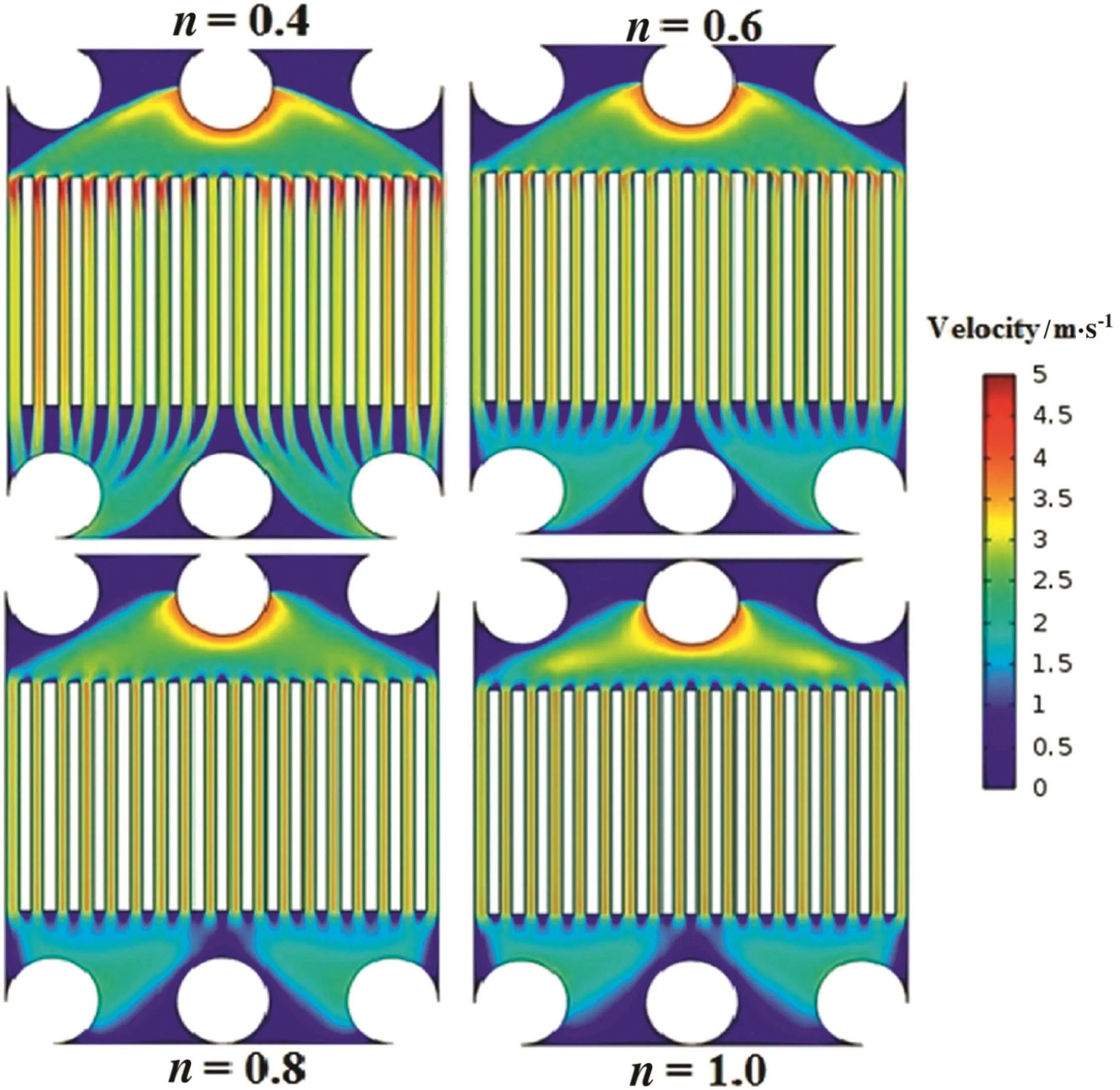
Fig.4.Surface plot of velocity in the microchannel plate of power-law fluids with different flow indexes(u0=4 m·s-1).
As can be seen,the velocity increases with an increment of flow index.That is,the average velocity forn=1 is higher than that ofn=0.4.Athigher flow indexes,the velocity profiles of different microchannel slits are more consistent with each other than lower flow indexes.For instance,the velocity profiles related ton=0.4 are nonuniform along the microchannel slits in contrast withn=1.Except the last left slit,the profiles are more and less similar forn=1.The sensitivity of viscosity to shear rate for power-law fluids,is higher for lower flow indexes.Thus the velocity profiles are more variable for these fluids than those for Newtonian fluid.
Table 1 shows the difference between maximum and minimum velocities along the microchannel slits.The difference between maximum and minimum velocities is higher for lower flow indexes.However,these differences are not very much.For example,when the inlet velocity is 4 m·s-1,the velocity difference(Δv)forn=0.6 andn=1 are about 0.23(5.7%)and 0.12 m·s-1(3.1%),respectively.On the other hand,the pressure drops of pseudoplastic fluids are very smaller than Newtonian ones and additionally the velocity profile in the slits at low flow index is more smooth and plug like despite parabolic velocity profile forn=1(these will be discussed in the next sections).
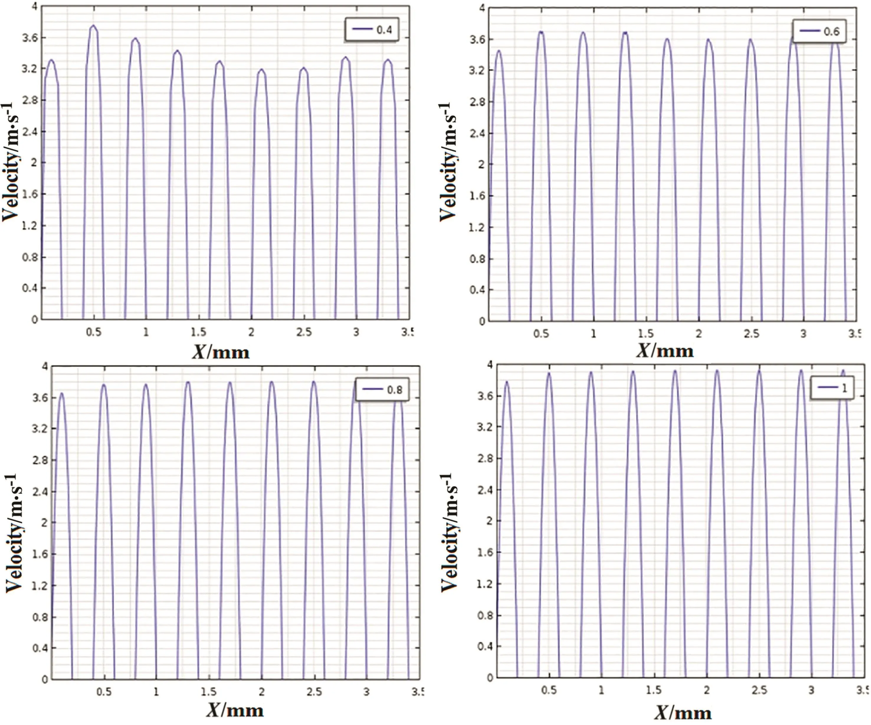
Fig.5.Velocity distribution along the microchannel plate slits for different flow indexes(u0=4 m·s-1).

Table 1Characteristics of the velocity distribution of power-law fluids with different flow indexes at the centerline of the microchannel.The data are based on maximum velocities
3.2.Velocity pro file in one microchannel slit
Since the flow rate atthe middle slitis higherthan others,its velocity profile is more susceptible to be non-uniform.Fig.6 compares the velocity profiles through the central microchannel slit for different flow indexes.As can be seen,the profile relates ton=1,have high gradient.The slope of curves declines as n decreases such that the profile relates ton=0.4 is approximately like the plug flow.Similar results were reported previously.For example,Zhaoet al.simulation showed that the velocity profile of power-law fluids becomes more plug-like as the fluid flow index decreases[41].Using momentum and continuity equations the velocity in a narrow slit(vz)can be expressed by[42]:wherep0,pL,B,xandLare pressure atentrance and exit point,half of slit width,distance from center of slit and slit length,respectively.The derivative ofvzwith respect toxis proportional to(x/B)1/n.The(x/B)is lesser than one and thus for larger 1/n(smallern)the velocity profile slope tends to zero.This means that the residence time distribution in one slit is narrow for small n and the fluid particles in different position(x)have the same velocity and exit from the slit at the same time.

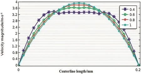
Fig.6.Comparison of velocity profiles in one slit(middle slit)for different flow indexes(u0=4 m·s-1).
Table 2 summarizes the distribution characteristics of the velocity profiles which confirm the above observations.The standard deviation increases with increase in the flow index.Also the maximum to average velocity ratio is higher for Newtonian fluids than power-law fluids.The difference is more distinctive at higher flow rates.It is noteworthy that in the Balajiet al.work the main attention was to average velocity in different microchannels[38],while the velocity distribution through each slit of the microchannel is as important as average velocity.This can be very important as any non-uniformity can decrease the performance of the system.
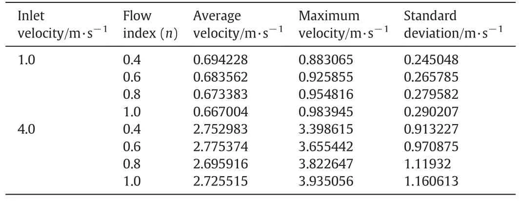
Table 2Characteristics of the velocity profiles of power-law fluids for different flow indexes through the middle slit of the microchannel
3.3.Velocity distribution at the outlets
Fig.7 shows the velocity profile along the arc length of the left microchannel outlet.Due to microchannel symmetry form,the velocity profile for the right outlet is the same as the left one and thus not shown here.Itisinteresting to note thateven forn=1,the velocity profile at the middle zone ofthe outletarc length is approximately plug-like and the velocity is approximately constant.However,it seems that the length of this zone(plateau length)is longer for low flow index(n=0.4).This can be important because the velocity out of the plateau zone decreases rapidly and at the corners of the outlet tends to zero value.The zero velocities lead to stagnation points and reduce the efficiency of the microchannel plate.These dead zones are the limitations of this geometry as mentioned by Ballajet al.[38].Therefore fluids with a low flow index can be used to lessen these zones and overcome the drawback of this geometry.

Fig.7.Velocity profiles along arc length of the left outlet for different flow indexes(u0=1 m·s-1).
Table 3 shows the plateau length,maximum and standard deviation for these velocity profiles.The velocity profile with lower n has smaller maximum velocity.The maximum velocity forn=1 is about20%larger than that ofn=0.4.However,the velocity distribution is more uniform for lowern.The variance of velocity distribution is higher for largernwhich is the same as the previous section.It is interesting that the average velocities over the outlet arc for different flow indexes are the same.It is expected,because the problem was solved for the steady state situation.Due to continuity and incompressibility assumption of the fluid,the outlet mass flows must be equal to the inlet one and thus the average velocities at the outlets will be the same.
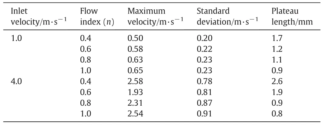
Table 3Maximum,standard deviation and plateau length of velocity profiles along arc length of the left outlet
3.4.Pressure drop
Microdevices with high flow output cause to high pressure drop.Thus,a higher pressure should be applied at the inlet port and this leads to higher energy consumption and in addition more expensive equipments are needed.For example,it is well known that the pumping power is proportion to the pressure difference between the inlet and outlet of the devices[43].Therefore the reduction of pressure difference can decrease energy consumption.
In this section the pressure drop through the inlet and outlet zones was studied.Table 4 shows the pressure drop at different inlet velocities.It is very interesting that when the inlet velocity is 4 m·s-1,the pressure drop forn=0.4(3.5 kPa)is about 1000 times smaller than that of Newtonian fluid(3294.5 kPa).This huge difference can actually save a large amount of energy.Even at lower inlet velocity(1 m·s-1),the pressure drop forn=1 is more than 300 times larger than that ofn=0.4.Thus with increasing throughput in the microchannel,the difference gets larger.For more investigation,the pressure drop can be evaluated from Eq.(5)by supposing that the mostpressure drop occurs along the slits of the microchannel plate:


Table 4Pressure drop through the inlet and outlet zones
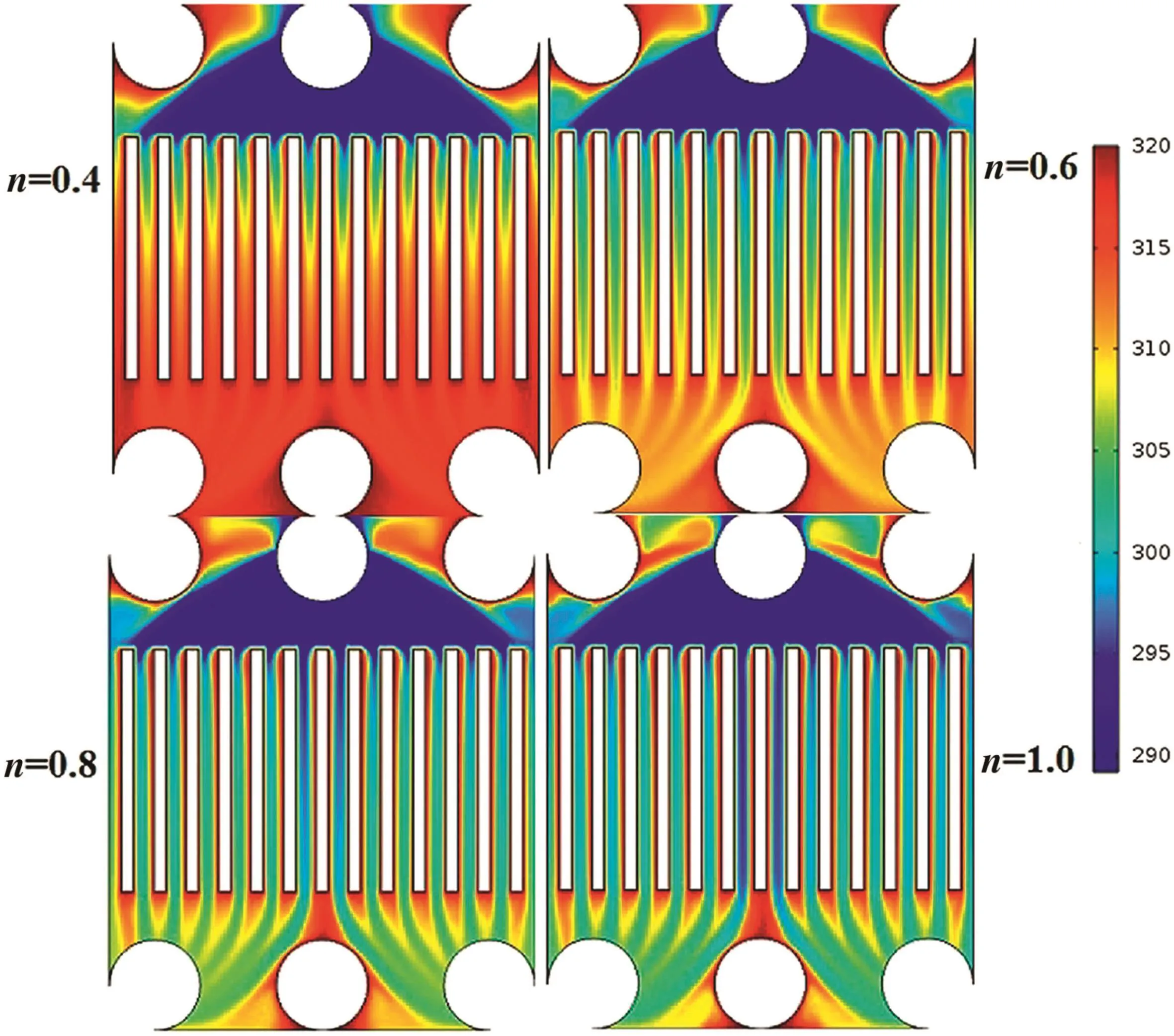
Fig.8.Temperature profile through the microchannel plate for power-law fluids with different flow indexes(Re′=1000).
From the above equation,it is clear that at the same flow velocity(Vy)and position(x),the ΔPdecreases rapidly as flow index decreases.Inversely,if the same ΔPapplied to the microchannel,the flow rate is proportion to ΔP1/nwhich means that for pseudoplastic fluids the flow rate willbe very largerthan Newtonian fluids at the sameΔP.Asa result,it is possible to achieve high flow rates with small ΔP.Addition of small amount of polymers to low molecular weight solvents(e.g.water)can change their rheological properties from Newtonian behavior to power-law fluids[44].These modified fluids can be replaced by commonfluids in microdevices to decrease energy consumption.Consequently,it is possible to use this microchannel plate configuration using powerlaw fluids even under high velocity conditions,without much energy consumption or large non-uniformity in the flow distribution.
3.5.Heat transfer
Fig.8 shows the temperature profiles through the microchannel for different power-law flow indexes at Reynolds number of 1000.The outlet temperature increases with the decrease of the flow index.According to Eq.(7),at constant Reynolds number the inlet velocity decreases with the decrease of the flow index.When the flow rate decreases,the fluid has more time span to contact with the hot walls.Therefore,its final temperature increases significantly.

Fig.9.Effect of Reynolds number on the friction factor and Nusselt number for fluids with different flow indexes.

Fig.10.Temperature profile of the microchannel with different channel numbers(n=0.8,Re′=1000).
Fig.9 displays the effectofReynolds number on the friction factor and Nusseltnumber fordifferent flow indexes.Itseems that the friction factor decreases with increment of Reynolds number.It is well known that the friction factor is inversely proportional to Reynolds number.Though,this reduction is more significant at low Reynolds number.Also,the friction factor and Nusselt number have higher values for fluids with higher flow index due to their higher pressure drop through the microchannel.Although the difference between the fluids is not significant at high Reynolds number.These findings are in consistence with the other results in the literature.For example,Raoet al.[31]showed that the pressure drag coefficient decreases with the decrease of power-law flow index and with increase in the Reynolds number,the effect of power-law index becomes smaller.The Nusselt number increases with increment of Reynolds number and power-law index at constant Reynolds number.As mentioned above,atconstant Reynolds number,the velocity decreases with decrease of power-law index.Therefore the Nusselt number was lower for power-law fluids than that of Newtonian fluid.
Fig.10 shows the temperature profile of the microchannel with different channel numbers.It is obvious that the outlet temperature increases with increase of the channel numbers.Higher channel number increases the surface area and raises the heat transfer and the fluid final temperature.Fig.11 shows the effect of channel number on the friction factor and Nusselt number for fluids with different power-law indexes.The friction factor and Nusselt number have higher values for Newtonian fluid than pseudoplastic fluids.The effect of channel number on the friction factor and Nusselt number is contradictory.Firstly,both friction factor and Nusselt number increase rapidly,when the channel number increases.However,the friction factor decreases rapidly and past through a minimum and again rises slowly.In the case of Nusselt number,the trend is more complicated and depends on the flow index.For example,the Nusselt number for Newtonian fluid increases at low channel number and then decreases.But for fluid with low power-law index(n=0.4)the Nusselt number increases monotonically with increase in the channel number.This shows that the power-law fluids with low fluid index have higher heat transfer efficiency.
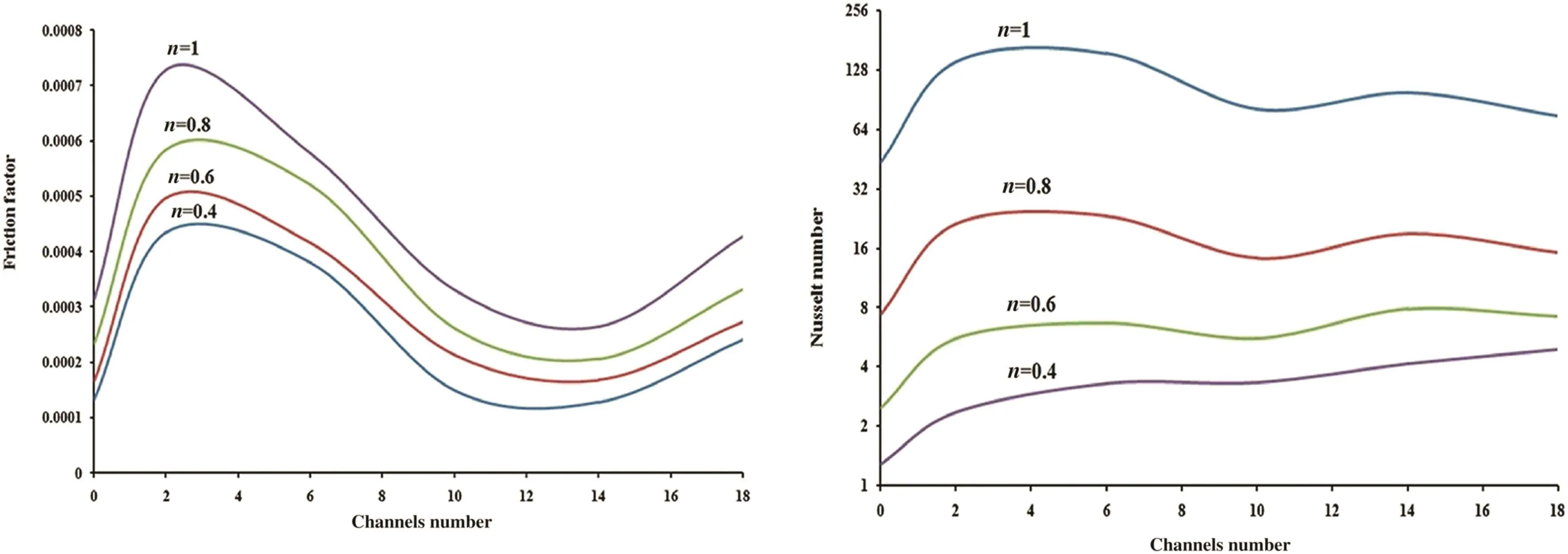
Fig.11.Effect of channel number on the friction factor and Nusselt number for fluids with different power-law indexes.
4.Conclusions
The flow distribution,pressure drop and heat transfer of power-law fluids with different flow-indexes at a microchannel plate have been studied under different operating conditions.The velocity profile along various microchannel slits was more similar for Newtonian fluid.Howeverthe non-uniformity forpseudoplastic fluids was not significant.On the other hand,the study of velocity distribution for low flow index fluids in one microchannel slit was similar to the plug flow.The velocity profile forn=1 was parabolic and was very non-uniformwhich can lead to different residence time for particles with different position.Also the velocity distribution through the outlet was studied.The results showed that the fluids with low flow index(n=0.4)had more uniform velocity profiles than that of Newtonian fluid.In addition,the power-law fluids with lower n have smaller stagnation zones.The most interesting results were the pressure difference between the inlet and outlet ports.The pressure drop varied over a wide range for different flow-indexes.This variation can reach orders of magnitudes at high flow rates such that the pressure drop forn=0.4 was very smaller than that ofn=1.Also,the effect of Reynolds number and channel number on the friction factor and Nusselt number for power-law fluids with different flow indexes were investigated.The friction factor decreases with increase in Reynolds number in spite of Nusselt number.The effects of channel number were contradictory.At low channel number both friction factor and Nusselt number increase.But the friction factor decreases with increment of channel number.The Nusselt number of Newtonian fluid decreases with increase in channel number.However,for power-law fluid with flow indexn=0.4,the Nusseltnumber increases continuously as the number of channels increases.These results show the use of pseudoplastic power-law fluids in the microchannels such as microheat exchanger which can lower the pressure drop and increase the heat transfer efficiency.
[1]M.Mirzaei,M.Saffari Avval,H.Naderan,Heat transfer investigation of laminar developing flow of nanofluids in a microchannel based on Eulerian-Lagrangian approach,Can.J.Chem.Eng.92(6)(2014)1139-1149.
[2]N.García-Hernando,A.Acosta-Iborra,U.Ruiz-Rivas,M.Izquierdo,Experimental investigation of fluid flow and heat transfer in a single-phase liquid flow micro-heat exchanger,Int.J.Heat Mass Transf.52(23)(2009)5433-5446.
[3]D.Aston,C.Berven,B.Williams,A.Basu,Mathematical analysis of effects on the electrostatic double layer of nanoscale surfaces in micro fluidic channels,Can.J.Chem.Eng.90(4)(2012)1059-1065.
[4]J.T.Adeosun,A.Lawal,Numerical and experimental mixing studies in a MEMS-based multilaminated/elongational flow micromixer,Sensors Actuators B Chem.139(2)(2009)637-647.
[5]R.E.Billo,C.R.Oliver,R.Charoenwat,B.H.Dennis,P.A.Wilson,J.W.Priest,H.Beardsley,A cellular manufacturing process for a full-scale biodiesel microreactor,J.Manuf.Syst.37(2015)409-416.
[6]L.Wang,X.Kong,Y.Qi,Optimaldesign for split-and-recombine-type flow distributors of microreactors based on blockage detection,Chin.J.Chem.Eng.(2016)897-903.
[7]A.P.Wong,R.Perez-Castillejos,J.C.Love,G.M.Whitesides,Partitioning microfluidic channels with hydrogel to construct tunable 3-D cellular microenvironments,Biomaterials29(12)(2008)1853-1861.
[8]E.Leclerc,K.Furukawa,F.Miyata,Y.Sakai,T.Ushida,T.Fujii,Fabrication of microstructures in photosensitive biodegradable polymers for tissue engineering applications,Biomaterials25(19)(2004)4683-4690.
[9]Y.Yamaguchi,T.Arakawa,N.Takeda,Y.Edagawa,S.Shoji,Development of a poly-dimethylsiloxane micro fluidic device for single cell isolation and incubation,Sensors Actuators B Chem.136(2)(2009)555-561.
[10]X.Zhang,X.Wu,R.Peng,D.Li,Electromagnetically controlled microfluidic chip for DNA extraction,Measurement75(2015)23-28.
[11]F.Zhao,Y.Lu,K.Wang,G.Luo,Kinetic study on selective extraction of HCl and H3PO4in a microfluidic device,Chin.J.Chem.Eng.24(2)(2016)221-225.
[12]X.Ge,H.Zhao,T.Wang,J.Chen,J.Xu,G.-S.Luo,Microfluidic technology for multiphase emulsions morphology adjustment and functional materials preparation,Chin.J.Chem.Eng.(2016)677-692.
[13]J.Wang,Y.Wang,G.Luo,Preparation of silica-alumina hollow spheres with a single surface hole by co-axial microchannel,Chin.J.Chem.Eng.22(11)(2014)1352-1356.
[14]J.T.Adeosun,A.Lawal,Numerical and experimental studies of mixing characteristics in a T-junction microchannel using residence-time distribution,Chem.Eng.Sci.64(10)(2009)2422-2432.
[15]B.J.Jones,P.-S.Lee,S.V.Garimella,Infrared micro-particle image velocimetry measurements and predictions of flow distribution in a microchannel heat sink,Int.J.Heat Mass Transf.51(7)(2008)1877-1887.
[16]V.Zivkovic,P.Zerna,Z.Alwahabi,M.Biggs,A pressure drop correlation for low Reynolds number Newtonian flows through a rectangular orifice in a similarly shaped micro-channel,Chem.Eng.Res.Des.91(1)(2013)1-6.
[17]B.Srinivas,Electroosmotic flow of a power law fluid in an elliptic microchannel,Colloid Surf.A492(2016)144-151.
[18]Q.Zhu,S.Deng,Y.Chen,Periodical pressure-driven electrokinetic flow of power-law fluids through a rectangular microchannel,J.Non-Newtonian Fluid Mech.203(2014)38-50.
[19]M.D.Stocks,T.Bello-Ochende,J.P.Meyer,Maximum thermal conductance for a micro-channel,utilising Newtonian and non-Newtonian fluid,Heat Mass Transf.50(6)(2014)865-875.
[20]S.Bijjam,A.K.Dhiman,CFD analysis of two-dimensional non-Newtonian power-law flow across a circular cylinder confined in a channel,Chem.Eng.Commun.199(6)(2012)767-785.
[21]R.Mohebbi,M.Nazari,M.Kayhani,Comparative study of forced convection of a power-law fluid in a channel with a built-in square cylinder,J.Appl.Mech.Tech.Phys.57(1)(2016)55-68.
[22]T.Hayat,H.Yasmin,A.Alsaedi,Convective heat transfer analysis for peristaltic flow of power-law fluid in a channel,J.Braz.Soc.Mech.Sci.Eng.37(2)(2015)463-477.
[23]M.Shojaeian,M.Yildiz,A.Koşar,Convective heat transfer and second law analysis of non-Newtonian fluid flows with variable thermophysical properties in circular channels,Int.Commun.Heat Mass Transfer60(2015)21-31.
[24]S.Yigit,R.J.Poole,N.Chakraborty,Effects of aspect ratio on laminar Rayleigh-Bénard convection of power-law fluids in rectangular enclosures:A numerical investigation,Int.J.Heat Mass Transf.91(2015)1292-1307.
[25]A.K.Baranwal,R.P.Chhabra,Free convection in confined power-law fluids from two side-by-side cylinders in a square enclosure,Heat Transfer Eng.(2016)1-55.
[26]N.S.Akbar,A.W.Butt,Heat transfer analysis for the peristaltic flow of Herschel-Bulkley fluid in a nonuniform inclined channel,Z.Naturforsch.A70(2015)23-32.
[27]A.K.Dhiman,S.Kumar,Non-Newtonian power-law flow across a confined triangular bluff body in a channel,Korean J.Chem.Eng.30(1)(2013)33-44.
[28]M.-H.Sun,X.-R.Zhang,Non-Newtonian nanofluid in a micro planar sudden expansion considering variable properties,Int.J.Therm.Sci.107(2016)316-329.
[29]F.Nikfarjam,A.Sohankar,Power-law fluids flow and heat transfer over two tandem square cylinders:Effects of Reynolds number and power-law index,Acta Mech.224(5)(2013)1115-1132.
[30]M.Bouhalleb,H.Abbassi,Pressure drop and heat transfer enhancement in a plane channel with a built-in bluff body:A comparison between triangular prism and square cylinder,Prog.Comput.Fluid Dyn.Int.J.14(5)(2014)295-303.
[31]P.K.Rao,A.K.Sahu,R.Chhabra,Momentum and heat transfer from a square cylinder in power-law fluids,Int.J.Heat Mass Transf.54(1)(2011)390-403.
[32]R.P.Bharti,D.J.Harvie,M.R.Davidson,Fully developed flow of power-law fluid through a cylindrical microfluidic pipe:Pressure drop and electroviscous effects,ASME 2008 Fluids Engineering Division Summer Meeting Collocated With the Heat Transfer,Energy Sustainability,and 3rd Energy Nanotechnology Conferences,American Society of Mechanical Engineers,2008.
[33]E.I.Borzenko,K.Boyarkina,G.R.Shrager,Pressure losses of power-law fluid flow through an axisymmetric sudden contraction,Key Eng.Mater.685(2016)47-50.
[34]I.T.Dosunmu,S.N.Shah,Pressure drop predictions for laminar pipe flow of carreau and modified power law fluids,Can.J.Chem.Eng.93(5)(2015)929-934.
[35]A.Babaie,M.H.Saidi,A.Sadeghi,Heat transfer characteristics of mixed electroosmotic and pressure driven flow of power-law fluids in a slit microchannel,Int.J.Therm.Sci.53(2012)71-79.
[36]P.Li,Y.Xie,D.Zhang,Laminar flow and forced convective heat transfer of shear-thinning power-law fluids in dimpled and protruded microchannels,Int.J.Heat Mass Transf.99(2016)372-382.
[37]D.Mei,L.Liang,M.Qian,X.Lou,Modeling and analysis of flow distribution in an A-type microchannel reactor,Int.J.Hydrog.Energy38(35)(2013)15488-15499.
[38]S.Balaji,S.Lakshminarayanan,Improved design of microchannel plate geometry for uniform flow distribution,Can.J.Chem.Eng.84(6)(2006)715-721.
[39]P.K.Swamee,N.Aggarwal,Explicit equations for laminar flow of Herschel-Bulkley fluids,Can.J.Chem.Eng.89(6)(2011)1426-1433.
[40]N.Sahiti,A.Lemouedda,D.Stojkovic,F.Durst,E.Franz,Performance comparison of pin fin in-duct flow arrays with various pin cross-sections,Appl.Therm.Eng.26(11)(2006)1176-1192.
[41]C.Zhao,E.Zholkovskij,J.H.Masliyah,C.Yang,Analysis of electroosmotic flow of power-law fluids in a slit microchannel,J.Colloid Interface Sci.326(2)(2008)503-510.
[42]R.B.Bird,W.E.Stewart,E.N.Lightfoot,Transport Phenomena,Wiley,New York,2007.
[43]M.R.Patel,Introduction to Electrical Power and Power Electronics,Taylor&Francis,London,2012.
[44]G.A.Stahl,D.N.Schulz,Water-soluble Polymers for Petroleum Recovery,Springer,New Jersey,2012.
杂志排行
Chinese Journal of Chemical Engineering的其它文章
- Heat transfer and friction factor of Therminol liquid phase heat transfer fluid in a ribbed tube☆
- A numerical study on heat transfer enhancement and design of a heat exchanger with porous media in continuous hydrothermal flow synthesis system
- Investigation of droplet breakup in liquid-liquid dispersions by CFDPBM simulations:The influence of the surfactant type
- Mixed convection characteristics in lid-driven cavity containing heated triangular block
- Superhydrophobic modification of ceramic membranes for vacuum membrane distillation☆
- Synthesis,characterization and application of PVA/ionic liquid mixed matrix membranes for pervaporation dehydration of isopropanol
