考虑粗糙度敏感位置的钝尾缘翼型气动性能研究
2017-05-25刘海龙王格格
张 旭,刘海龙,王格格,李 伟
考虑粗糙度敏感位置的钝尾缘翼型气动性能研究
张 旭1,2,刘海龙1,王格格1,李 伟2,3
(1. 天津工业大学天津市现代机电装备技术重点实验室,天津 300387;2. 建筑安全与环境国家重点实验室,北京 100013;3. 天津城建大学能源与安全工程学院,天津 300384)
针对考虑粗糙度敏感位置的风力机翼型钝尾缘改型前后的气动性能进行研究,揭示钝尾缘改型对表面粗糙翼型增升效果的影响规律。基于-SST湍流模型,计算表面光滑与粗糙的S822翼型的升、阻力系数,并与试验结果进行比较;采用坐标旋转变换与缩放横纵坐标系数相结合的方法,建立钝尾缘改型型线数学表达式,分析对称钝尾缘改型増升效果得到S822翼型的最佳尾缘厚度;研究吸力面和压力面布置粗糙度时翼型的气动性能,获得上、下翼面的粗糙度敏感位置;对具有粗糙度敏感位置的翼型按最佳尾缘厚度进行钝尾缘改型,计算改型前后翼型的升、阻力系数和升阻比,并分析尖、钝尾缘翼型的粗糙度敏感性。结果表明:翼型进行钝尾缘改型的最佳尾缘厚度为2%弦长;吸力面和压力面的粗糙度敏感位置分别为距前缘1%弦长和5%弦长处;钝尾缘改型使升力系数和最大升阻比均明显升高,显著改善了表面粗糙翼型的气动性能,且尖、钝尾缘翼型的粗糙度敏感性综合指标值为10.68%和8.15%,降低了翼型对粗糙度位置的敏感性。研究结论可为表面粗糙风力机叶片翼型的设计和优化提供指导。
风力机;翼型;粗糙度;敏感位置;钝尾缘改型;气动性能
0 引 言
安装于高寒、沿海地带的风力机,经常遇到灰尘、昆虫以及雨雪等,叶片表面会出现污垢附着现象。污垢会改变叶片气动外形并增大表面粗糙度,从而导致风能转化率降低[1-8]。而钝尾缘改型能增加最大升力和失速攻角,降低最大升力对前缘粗糙的敏感度[9-11]。因此,研究表面粗糙翼型钝尾缘修改后的气动性能对提高风力机的风能利用系数具有重要意义。
针对粗糙度对翼型气动性能的影响,很多学者开展了一系列数值与试验研究。Khalfallah等[12]实验分析叶片表面积灰形成的粗糙度对风力机出力的影响,研究表明随灰尘的积累,升力下降,阻力升高,且积灰降低了风力机的输出功率。Soltani等[13]通过风洞试验、Ferrer等[14]利用计算流体动力学(computational fluid dynamics,CFD)方法以及Sagol等[1]采用数值模拟和风洞试验相结合,均获得表面粗糙度降低翼型的气动性能以及翼型前缘对粗糙度最敏感等结论。包能胜等[15]利用粗糙带贴片试验,研究压力面前缘粗糙度对叶型气动性能的影响,结果表明升力系数在失速之后变化非常大,阻力系数变化很小。陈进等[16]探讨了前缘粗糙条件对翼型气动特性的影响,并优化设计得到一种风力机专用新翼型。李德顺等[17]数值研究粗糙度对风力机翼型气动性能的影响,结果显示适当增加压力面后缘粗糙度可提高升力系数,且升阻比始终低于光滑表面的翼型。但吴攀等[18]研究发现该结论并不适用于FFA-W3-211翼型。张骏等[19]采用CFD方法研究风力机积灰和昆虫引起的粗糙度效应,结果表明前缘粗糙度严重影响翼型的气动性能,压力面尾缘布置适当粗糙度却有积极作用。以上文献并未涉及通过降低粗糙度敏感性提高翼型气动性能的研究。
此外,国内外学者也在风力机钝尾缘翼型气动性能的研究方面取得了一些进展。Baker等[20]用风洞试验研究钝尾缘翼型的气动性能,发现适度增加尾缘厚度可增大升阻比并减小对前缘过渡的敏感性。Standish等[21]采用4种数值解法对钝尾缘翼型进行数值模拟,研究表明钝尾缘改型能增加最大升力和升力曲线斜率,降低过早的边界层转捩。韩中合等[22]通过改进翼型尾部的Gurney襟翼形成钝尾缘翼型,分析翼型修改前后风力机的功率输出特性。刘杰平等[23]利用XFOIL软件比较不同尾缘加厚方式所得翼型的气动性能。杨瑞等[24]采用CFD方法模拟薄、钝尾缘翼型的气动性能,结果显示钝尾缘翼型增大了最大升力系数,并降低前缘污染对升力特性的影响。马林静等[25]参数化研究尾缘厚度对风力机翼型气动性能的影响,发现尾缘厚度在一定范围内增大时,升、阻力系数增大,升阻比先增后降。徐浩然等[26]数值模拟尾缘对称加厚翼型的气动性能,结果表明最大升力系数随尾缘厚度增大而增大,但厚度应控制在约5%弦长范围内。然而,以上关于粗糙度和钝尾缘改型对翼型气动性能影响的研究多是单独开展的。针对表面粗糙的翼型进行尾缘对称加厚,研究考虑粗糙度敏感位置的钝尾缘改型对翼型气动性能的影响较少。
本文以美国可再生能源实验室设计的风力机专用翼型S822为研究对象,建立钝尾缘改型型线公式并进行改型。考虑钝尾缘的最佳厚度以及粗糙度敏感位置,采用CFD方法对表面粗糙翼型钝尾缘修改后的气动性能进行详细研究,并分析尖、钝尾缘翼型的粗糙度敏感性。
1 计算模型及方法
基于CFD软件Fluent,计算表面光滑与粗糙的S822翼型气动性能,并与试验结果进行比较分析。
1.1 几何模型
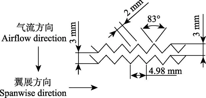
S822翼型广泛应用于风力机叶片的主要功率产生区,具有16%的最大相对厚度,以及最大相对弯度为1.92%。风洞试验在美国伊利诺伊大学香槟分校的低紊流亚音速风洞进行,雷诺数=5×10⁵,风速24.38 m/s,翼型弦长0.305 m。使用图1所示Zigzag粗糙带,分别布置在上、下翼面距前缘2%和5%位置处[27]。粗糙带厚0.33 mm,沿翼展方向相邻锯齿齿尖距离4.98 mm,齿尖角度83°,由此可计算出沿气流方向相邻锯齿齿尖距离为3 mm。

图1 Zigzag粗糙带几何尺寸
为了较好模拟风洞试验,并与数据进行对比,表面光滑与粗糙的S822翼型几何模型的弦长同样选用 0.305 m。采用凸台描述试验中的粗糙带,建立翼型粗糙度模型。凸台高0.33 mm(即粗糙带厚),宽3 mm(即沿气流方向相邻锯齿齿尖距离)。
利用Fluent的前处理软件Gambit生成翼型的几何模型、计算域和网格,如图2所示。计算域由一个直径为50的半圆形和一个长50、宽25的矩形构成,翼型位于半圆中心。表面光滑的S822翼型计算网格采用C型四边形网格。在光滑翼型上布置320个节点,采用边界层进行近壁面加密。边界层首层网格高度10-5m,共划分15层,壁面率值小于5。表面布置粗糙度的S822翼型几何形状较复杂,采用分块结构化网格处理凸台区域。沿凸台侧边引出与半圆边界相交的线段,将表面粗糙翼型的半圆形计算域分成6部分,每部分均构成四边形。使用映射网格进行划分,得到结构化C型网格。在含粗糙度的翼型上布置380个节点,且边界层同表面光滑的S822翼型,值也小于5。

注:A和B为光滑和粗糙翼型的网格局部放大图。
1.2 控制方程
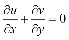
风力机翼型绕流为不可压缩流动[28],其控制方程为连续性方程

和二维不可压缩Navier-Stokes方程
(2)
1.3 计算方法
使用Fluent软件进行翼型的气动性能数值计算。-SST湍流模型综合了-与-模型的优势,适合处理带有逆压梯度和分离流动的问题[29]。压力和速度耦合采用SIMPLE算法,各方程离散格式均采用二阶迎风格式。速度和连续性方程的残差值分别为10-6和10-4,和方程的为10-5。计算域左侧及上下两侧进流边界设定为速度入口,风速由=5×10⁵确定,湍流强度为0.05%。计算域右侧出流边界设定为压力出口,表压力给定0 Pa。翼型表面设定为固壁绝热无滑移边界条件。
1.4 网格无关性与模型适应性验证
利用上述计算模型及方法,计算攻角在-5.17º~20º之间变化时表面光滑和粗糙的S822翼型的升、阻力系数,并与文献[27]的风洞试验结果进行对比,如图3所示。表面光滑和粗糙的S822翼型的网格数分别采用74 990、 95 185、112 740和79 214、109 046、128 546。

图3 光滑和粗糙的S822翼型计算值与试验值比较
由图3可知,表面光滑的S822翼型的升、阻力系数在74 990、95 185和112 740网格数下均相差很小,表面粗糙的S822翼型在79 214、109 046和28 546网格数下亦如此。考虑到节省计算资源,光滑和粗糙的翼型的网格数分别采用95 185和109 046比较合适,均可得到精确的计算结果。
由图3a可知,光滑翼型的升、阻力系数分别在8.19°和10.19°攻角之前与试验值吻合良好,在8.19°和10.19°攻角之后高于、低于试验值。由图3b可知,粗糙翼型的升力系数在攻角小于4.06°时与试验值比较接近,在4.06°攻角之后略高于试验值;阻力系数在11.19°攻角之前与试验值吻合很好。总体来看,表面光滑和粗糙的翼型的气动性能计算值均与试验值基本相同,且总体变化趋势一致,故可采用本文数值模型和方法进行模拟计算。
2 钝尾缘改型公式及最佳尾缘厚度
建立钝尾缘改型型线的数学表达式,数值计算S822翼型的不同尾缘厚度钝尾缘改型的气动性能。分析尾缘厚度对翼型的升、阻力系数和升阻比的影响,获得钝尾缘改型时最佳的尾缘厚度。
2.1 钝尾缘改型公式
原始S822翼型的型线如图4a所示。在不改变翼型的最大相对厚度及其位置、弯度和弦长的情况下,利用坐标旋转变换以及缩放横纵坐标系数建立图4a所示钝尾缘改型型线的数学表达式。

a. S822翼型钝尾缘改型示意图
a. Curve design of S822 airfoil and its blunt trailing-edge modification

注::虚线为经过坐标旋转变换得到的翼型型线;r为的长度,m;α为与轴的夹角,rad;β和φ为逆、顺时针旋转角度,rad;h为尾缘厚度,m;、、为尖、钝尾缘和坐标旋转后的翼型控制点坐标;S822_1、S822_2、S822_3、S822_4为尾缘厚度为1%c、2%c、3%c和4%c的对称钝尾缘翼型;c为翼型弦长,m。

(5)
将式(3)带入式(4)和式(5),可得
(7)
经过坐标旋转变换,翼型的弦长变短。此时,可通过上、下翼面型线的横坐标分别乘以因式和保证改型后翼型弦长不变,其中和为上、下翼面旋转后尾缘点的横坐标。因此,钝尾缘改型上、下翼面横坐标的表达式为

为使钝尾缘改型与原翼型具有相同的最大相对厚度及其位置,基于有限元方法中形函数的思想,将坐标旋转后翼型上、下翼面的纵坐标分别减去和加上,从而得到钝尾缘改型上、下翼面纵坐标的表达式
(9)
采用式(8)和式(9)对S822翼型进行尾缘厚度为1%、2%、3%和4%的对称钝尾缘改型,翼型型线如图4b所示。并用S822_1、S822_2、S822_3和S822_4分别表示上述4种尾缘厚度情况。
2.2 最佳尾缘厚度
图5为S822翼型及其钝尾缘改型的升、阻力系数和升阻比随攻角变化的曲线。由图5a可知,4种改型的升力系数在0.03°攻角之前比较接近,0.03°攻角之后随尾缘厚度增加呈先增大后减小的趋势,S822_1、S822_2和S822_3改型的升力系数均高于原型和S822_4改型,且S822_4改型的升力系数在5.09°攻角之后低于S822翼型。由图5b可知,阻力系数在-5.17º~20º攻角范围内十分接近。

图5 不同尾缘厚度翼型的升、阻力系数和升阻比
由图5c可知,4种改型的升阻比在1°攻角之前很接近,且均高于S822翼型;在1°~8.19°攻角范围内,升阻比随尾缘厚度增加而先增后减,S822_2改型的最大。在8.19°攻角之后,S822_1、S822_2和S822_3改型的升阻比与原型相差不大,且S822_3改型在9.17°~12.22°攻角之间高于原型及其他改型。S822_4改型的升阻比在3.07°攻角之后低于其他翼型。S822_2改型的最大升阻比高于原型及其他改型。综上所述,钝尾缘改型时,并不是尾缘厚度越大翼型的气动性能越好。S822翼型对称钝尾缘改型的最佳尾缘厚度为2%。
3 粗糙度位置对翼型气动性能的影响
为了研究粗糙度位置对翼型气动性能的影响,分别在翼型吸力面与压力面的距前缘1%、2%、5%、10%、20%、30%、40%、50%、60%、90%、100%位置处布置一个高0.33 mm、宽3 mm的凸台,进行翼型的升、阻力系数和升阻比计算。
3.1 吸力面布置粗糙度翼型的气动性能
图6为吸力面布置粗糙度的翼型的升、阻力系数和升阻比随粗糙度位置变化的曲线。由图6a和图6b可知,升、阻力系数分别在7.16°和10.19°攻角之前非常接近。S822_1%_s、S822_2%_s和S822_5%_s翼型的升力系数在7.16°攻角之后随粗糙度位置靠近前缘而减小并低于光滑翼型,而阻力系数在10.19°攻角之后呈递增趋势且高于光滑翼型。吸力面其他位置粗糙的翼型的升力系数在7.16°~16°攻角之间和阻力系数均与光滑翼型十分接近,且升力系数在攻角大于16°之后明显高于光滑翼型。

注:S822_1%c_s、S822_2%c_s、S822_5%c_s、S822_10%c_s、S822_20%c_s、S822_30%c_s、S822_40%c_s、S822_50%c_s、S822_60%c_s为吸力面1%c、2%c、5%c、10%c、20%c、30%c、40%c、50%c、60%c位置处布置粗糙度的翼型。
由图6c可知,S822_1%_s、S822_2%_s和S822_ 5%_s翼型的升阻比在2°攻角之前相差不大,且均高于 光滑翼型,2°攻角之后随粗糙度位置靠近前缘而减小,并低于光滑翼型。吸力面其他位置粗糙的翼型的升阻比在6.17°攻角之前和12.22°攻角之后均与光滑翼型比较接近,6.17°~12.22°攻角之间低于光滑翼型。最大升阻比随吸力面粗糙度位置靠近前缘呈递减趋势,且低于光滑翼型。
3.2 压力面布置粗糙度翼型的气动性能
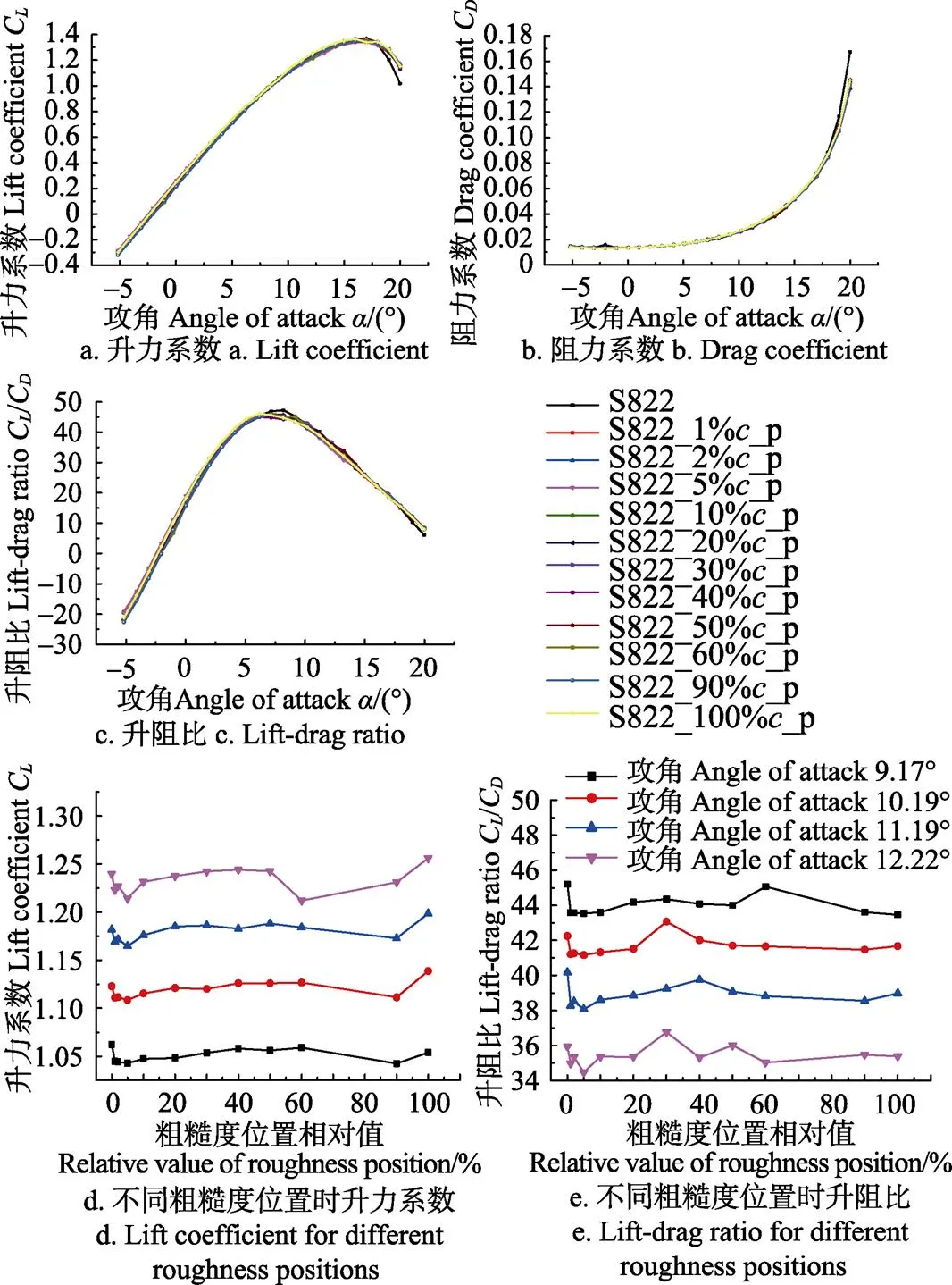
图7为压力面布置粗糙度的翼型的升、阻力系数和升阻比随粗糙度位置变化的曲线。由图7a和图7c可知,S822_1%_p、S822_2%_p、S822_5%_p和S822_100%_ p翼型的升力系数和升阻比均在3.07°攻角之前非常接近,且高于光滑翼型;压力面其他位置粗糙的翼型的升力系数和升阻比在攻角小于18°时与光滑翼型十分接近,18°攻角之后明显高于光滑翼型。S822_100%_p翼型的升力系数在3.07°~6.17°和10.19°~16°攻角范围内以及升阻比在3.07°~6.17°攻角之间高于压力面其他位置粗糙和光滑的翼型。S822_5%_p翼型的升力系数在9.17°~18°攻角之间以及升阻比在9.17°~13.3°攻角范围内均最小。压力面粗糙的翼型的升阻比在7.16°~9.17°和13.3°~18°攻角范围内分别低于和非常接近光滑翼型,最大升阻比相差不大且低于光滑翼型。由图7b可知,阻力系数在18°攻角之前十分接近,18°攻角之后低于光滑翼型。

注:S822_1%c_p、S822_2%c_p、S822_5%c_p、S822_10%c_p、S822_20%c_p、S822_30%c_p、S822_40%c_p、S822_50%c_p、S822_60%c_p、S822_90%c_p、S822_100%c_p为压力面1%c、2%c、5%c、10%c、20%c、30%c、40%c、50%c、60%c、90%c、100%c位置处布置粗糙度的翼型。
图7a和图7c描述压力面粗糙翼型的升力系数和升阻比随攻角变化的规律,并未清晰显示同一攻角下不同粗糙度位置对翼型气动性能的影响。因此,以9.17°~12.22°的4个攻角为例,分析升力系数和升阻比随粗糙度位置变化的情况,如图7d和图7e所示。由图7d和图7e可知,升力系数随攻角增加呈递增趋势,升阻比却呈递减趋势。升力系数和升阻比在粗糙度距前缘小于1%时快速减小,1%~5%范围内基本呈先增大后减小的趋势,5%位置处达到最小值。升力系数在粗糙度距前缘10%~50%之间时相差不大,50%~100%范围内呈先减小后增大的趋势。升阻比在粗糙度距前缘10%~50%范围内基本呈先增大后减小的趋势,60%~100%之间时比较接近,且低于光滑翼型。
分析可知,吸力面距前缘1%位置处布置粗糙度后,升、阻力系数和升阻比变化最剧烈,因而吸力面粗糙度敏感位置为距前缘1%处。压力面距前缘5%和100%位置处布置粗糙度后,升、阻力系数和升阻比变化都比较明显。但实际上翼型的前缘较易污染,研究前缘粗糙对翼型气动性能的影响更具有意义。因此,压力面粗糙度的敏感位置为距前缘5%处。
4 表面粗糙翼型改型后气动性能计算及粗糙度敏感性分析
利用建立的钝尾缘改型公式对表面粗糙的S822翼型进行尾缘厚度为2%的对称钝尾缘改型,研究考虑粗糙度敏感位置的钝尾缘改型对翼型的升、阻力系数和升阻比的影响规律,并进行尖、钝尾缘翼型的粗糙度敏感性分析。
4.1 钝尾缘改型对吸力面粗糙翼型气动性能的影响
在吸力面1%位置处布置粗糙度,翼型钝尾缘改型前后的升、阻力系数和升阻比随攻角变化的曲线如图8a、8b、8c所示。由图8a可知,相较于尖尾缘S822_1%_s翼型,S822_1%_s_2改型的升力系数明显升高。由图8b可知,改型的阻力系数在9.17°攻角之前与S822_1%_s翼型非常接近,9.17°攻角之后高于S822_1%_s翼型。由图8c可知,S822_1%_s_2改型的升阻比在攻角小于11.19°时高于S822_1%_s翼型,11.19°攻角之后低于S822_1%_s翼型。吸力面粗糙翼型的最大升阻比在钝尾缘改型后升高14.6%。
4.2 钝尾缘改型对压力面粗糙翼型气动性能的影响
在压力面5%位置处布置粗糙度,翼型钝尾缘改型前后的升、阻力系数和升阻比随攻角变化的曲线如图8d、8e、8f所示。由图8d和图8e可知,S822_5%_p_2改型的升、阻力系数分别在0.03°和10.19°攻角之前与S822_5%_p翼型非常接近,0.03°和10.19°攻角之后高于S822_5%_p翼型,而20°攻角时改型的升力系数低于S822_5%_p翼型。
由图8f可知,攻角小于1°以及在13.23°~16°之间变化时,S822_5%_p_2改型和S822_5%_p翼型的升阻比十分接近;在1°~13.23°攻角范围内和16°攻角之后,改型的升阻比分别高于、低于S822_5%_p翼型。S822_5%_ p_2改型的最大升阻比明显高于S822_5%_p翼型。
4.3 钝尾缘改型对表面粗糙翼型气动性能的影响
在吸力面1%和压力面5%两个位置处布置粗糙度,翼型钝尾缘改型前后的升、阻力系数和升阻比随攻角变化的曲线如图9所示。

图8 吸力面或压力面粗糙翼型钝尾缘(尾缘厚度为2%c)改型前后的升、阻力系数和升阻比

图9 粗糙翼型钝尾缘改型前后的升、阻力系数和升阻比
由图9a可知,S822_1%_s & 5%_p_2改型的升力系数高于S822_1%_s & 5%_p翼型。由图9b可知,改型的阻力系数在10.19°攻角之前与S822_1%_s & 5%_p翼型非常接近,10.19°攻角之后高于S822_1%_s & 5%_p翼型。由图9c可知,S822_1%_s & 5%_p_2改型的升阻比在11.19°攻角之前高于S822_1%_s & 5%_p翼型,11.19°攻角之后低于S822_1%_s & 5%_p翼型。钝尾缘改型后表面粗糙翼型的最大升阻比提升16.9%。
4.4 钝尾缘翼型粗糙度敏感性分析
为了定量地评价钝尾缘改型对翼型粗糙度敏感性的影响,需要找出一个评价指标。根据风力机叶片翼型的特点,取升力系数下降率和升阻比下降率的加权平均值作为粗糙度敏感性评价指标[30]。
定义升力系数下降率

定义升阻比下降率

根据文献[30]可知,升力系数下降率和升阻比下降率的权重系数分别为0.49和0.51,即综合指标。根据表面光滑和粗糙的尖、钝尾缘翼型的升力系数与升阻比计算结果,计算升力系数下降率、升阻比下降率以及综合指标值,如表1所示。由表1可以看出,钝尾缘翼型综合指标值为8.15%,低于尖尾缘翼型的10.68%,说明钝尾缘改型可使翼型具有更低的粗糙度敏感性。

表1 尖、钝尾缘翼型粗糙度敏感性综合指标值
注: CC′、(C/C)max、(C′/C′)max为光滑和粗糙翼型的升力系数、最大升阻比,δC、(C/C)为升力系数和升阻比的下降率。
Note:C, C′, (C/C)maxand (C′/C′)maxare the lift coefficients and the maximum lift-drag ratios of airfoils with smooth and rough surfaces;δC,(C/C) are the decline rates of lift coefficient and lift-drag ratio.
5 结 论
通过数值模拟研究,关于考虑粗糙度敏感位置的钝尾缘改型的增升效果可得到如下结论:
1)通过坐标旋转变换与缩放坐标系数,建立钝尾缘改型型线表达式;钝尾缘翼型的升力系数和升阻比随尾缘厚度增加而先增后减,且最大升阻比在尾缘厚度为2%(为翼型弦长)时最高。
2)吸力面1%、2%和5%位置处粗糙的翼型的升力系数随粗糙度位置靠近前缘而减小,且与升阻比均低于光滑翼型,阻力系数增大并高于光滑翼型;其他位置粗糙翼型的升、阻力系数与光滑翼型很接近。压力面5%位置处粗糙的翼型的升力系数在9.17°~18°攻角之间低于其他位置粗糙和光滑的翼型;压力面粗糙翼型的最大升阻比相差不大且低于光滑翼型。吸、压力面的粗糙度敏感位置分别为1%和5%处。
3)具有粗糙度敏感位置的翼型钝尾缘改型后,升力系数和最大升阻比均明显升高;尖、钝尾缘翼型的粗糙度敏感性综合指标值分别为10.68%和8.15%,钝尾缘改型使翼型对粗糙度位置的敏感性降低。
[1] Sagol E, Reggio M, Ilinca A. Issues concerning roughness on wind turbine blades[J]. Renewable and Sustainable Energy Reviews, 2013, 23(4): 514-525.
[2] Corten G P, Veldkamp H F. Insects cause double stall[C]//European Wind Energy Conference. Copenhagen, Denmark: 1999.
[3] Corten G P, Veldkamp H F. Insects can halve wind-turbine power[J]. Nature, 2001, 412(6842): 41-42.
[4] Morgan C, Bossanyi E, Seifert H. Assessment of safety risks arising from wind turbine icing [C]//BOREAS IV-Wind Energy Production in Cold Climate. Hetta, Finland: 1998: 113-121.
[5] Fu P, Farzaneh M. A CFD approach for modeling the rime-ice accretion process on a horizontal-axis wind turbine[J]. Journal of Wing Engineering and Industrial Aerodynamics, 2010, 98(4/5): 181-188.
[6] Lamraoui F, Fortin G, Benoit R, et al. Atmospheric icing impact on wind turbine production[J]. Cold Regions Science and Technology, 2014, 100(4): 36-49.
[7] Shu L C, Liang J, Hu Q, et al.Study on small wind turbine icing and its performance[J]. Cold Regions Science and Technology, 2017, 134(1): 11-19.
[8] 焦灵燕,汪建文,贺玲丽. 粗糙度对风力机翼型气动性能影响的模拟研究[J]. 可再生能源,2014,32(12):1816-1820. Jiao Lingyan, Wang Jianwen, He Lingli. Simulation study on effect of surface roughness on aerodynamic performance of wind turbine airfoil[J]. Renewable Energy Resources, 2014, 32(12): 1816-1820. (in Chinese with English abstract)
[9] Jackson K J, Zuteck M D, van Dam C P, et al. Innovative design approaches for large wind turbine blades[J]. Office of Scientific & Technical Information Technical Reports, 2003, 8(2): 141-171.
[10] Zhang X, Li W, Liu H L. Numerical simulation of the effect of relative thickness on aerodynamic performance improvement of asymmetrical blunt trailing-edge modification[J]. Renewable Energy, 2015, 80: 489-497.
[11] Yoo H S, Lee J C. Numerical analysis of NACA64-418 airfoil with blunt trailing edge[J]. International Journal of Aeronautical and Space Sciences, 2015, 16(4): 493-499.
[12] Khalfallah M G, Koliub A M. Effect of dust on the performance of wind turbines[J]. Desalination, 2007, 209(1): 209-220.
[13] Soltani M R, Birjandi A H, Moorani M S. Effect of surface contamination on the performance of a section of a wind turbine blade[J]. Scientia Iranica, 2011, 18(3): 349-357.
[14] Ferrer E, Munduate X. CFD predictions of transition and distributed roughness over a wind turbine airfoil[C]//47thAIAA Aerospace Sciences Meeting including the New Horizons Forum and Aerospace Exposition. Orlando, Florida: 2009, 1-13.
[15] 包能胜,倪维斗. 风力机翼型前缘表面粗糙度对气动性能影响[J]. 太阳能学报,2008,29(12):1465-1470. Bao Nengsheng, Ni Weidou. Influence of additional rough strap of wind turbine airfoil leading edge surface on aerodynamic performance[J]. Acta Energiae Solaris Sinica, 2008, 29(12): 1465-1470. (in Chinese with English abstract)
[16] 陈进,张石强,王旭东,等. 基于粗糙度敏感性研究的风力机专用翼型设计[J]. 空气动力学学报,2011,29(2): 142-149. Chen Jin, Zhang Shiqiang, Wang Xudong, et al. Dedicated wind turbine airfoil design based on the roughness sensitivity considerations[J]. Acta Aerodynamica Sinica, 2011, 29(2): 142-149. (in Chinese with English abstract)
[17] 李德顺, 李仁年, 杨从新, 等. 粗糙度对风力机翼型气动性能影响的数值预测[J]. 农业机械学报, 2011, 42(5): 111-115. Li Deshun, Li Rennian, Yang Congxin, et al. Numerical prediction of the effect of surface roughness on aerodynamic performance of a wind turbine airfoil[J]. Transactions of the Chinese Society for Agricultural Machinery, 2011, 42(5): 111-115. (in Chinese with English abstract)
[18] 吴攀, 李春, 叶舟, 等. 粗糙度对风力机专用翼型气动性能影响[J]. 流体机械, 2014, 42(1): 17-21, 62. Wu Pan, Li Chun, Ye Zhou, et al. Influence of roughness on aerodynamic performance of dedicated wind turbine airfoil [J]. Fluid Machinery, 2014, 42(1): 17-21, 62. (in Chinese with English abstract)
[19] 张骏, 袁奇, 吴聪, 等. 大型风力机叶片表面粗糙度效应数值研究[J]. 中国电机工程学报, 2014, 34(20): 3384-3391. Zhang Jun, Yuan Qi, Wu Cong, et al. Numerical simulation on the effect of surface roughness for large wind turbine blades[J]. Proceedings of the CSEE, 2014, 34(20): 3384-3391. (in Chinese with English abstract)
[20] Baker J P, Mayda E A, van Dam C P. Experimental analysis of thick blunt trailing-edge wind turbine airfoils [J]. Journal of Solar Energy Engineering, 2006, 128(4): 422-431.
[21] Standish K J, van Dam C P. Aerodynamic analysis of blunt trailing edge airfoils [J]. Journal of Solar Energy Engineering, 2003, 125(4): 479-487.
[22] 韩中合,焦红瑞. 加装钝尾缘改善风力机桨叶气动性能的研究[J]. 动力工程,2009,29(11):1073-1077.Han Zhonghe, Jiao Hongrui. Study on aerodynamic performance of airfoil by mounting a blunt trailing edge to wind blade[J]. Journal of Power Engineering, 2009, 29(11): 1073-1077. (in Chinese with English abstract)
[23] 刘杰平,陈培,张卫民. 后缘加厚方式对典型风力机翼型气动性能的影响[J]. 太阳能学报,2009,30(8):1092-1096. Liu Jieping, Chen Pei, Zhang Weimin. Influence of enlarging trailing edge thickness on the representative wind turbine airfoil’s aerodynamic performances[J]. Acta Energiae Solaris Sinica, 2009, 30(8): 1092-1096. (in Chinese with English abstract)
[24] 杨瑞,李仁年,张士昂,等. 钝尾缘风力机翼型气动性能计算分析[J]. 机械工程学报,2010,46(2):106-110. Yang Rui, Li Rennian, Zhang Shiang, et al. Computational analyses on aerodynamic characteristics of flatback wind turbine airfoils [J]. Journal of Mechanical Engineering, 2010, 46(2): 106-110. (in Chinese with English abstract)
[25] 马林静,陈江,杜刚,等. 尾缘厚度对风力机翼型气动特性影响参数化研究[J]. 太阳能学报,2010,31(8):1060-1067. Ma Linjing, Chen Jiang, Du Gang, et al. Parametric research on influence of trailing edge’s thickness to aerodynamic performance for wind turbine airfoils[J]. Acta Energiae Solaris Sinica, 2010, 31(8): 1060-1067. (in Chinese with English abstract)
[26] 徐浩然,杨华,刘超. 尾缘加厚的DU系列翼型气动性能数值分析[J]. 农业工程学报,2014,30(17):101-108.Xu Haoran, Yang Hua, Liu Chao. Numerical value analysis on aerodynamic performance of DU series airfoils with thickened trailing edge[J]. Transactions of the Chinese Society of Agricultural Engineering (Transactions of the CSAE), 2014, 30(17): 101-108. (in Chinese with English abstract)
[27] Selig M S, Mcgranahan B D. Wind tunnel aerodynamic tests of six airfoils for use on small wind turbines [R]. Golden, Colorado: National Renewable Energy Laboratory, 2003.
[28] 杨从新,巫发明,张玉良. 基于滑移网格的垂直轴风力机非定常数值模拟[J]. 农业机械学报,2009,40(6):98-102. Yang Congxin, Wu Faming, Zhang Yuliang. Numerical simulation on unsteady rotated flow of a vertical axis wind turbine based on moving meshes[J]. Transactions of the Chinese Society for Agricultural Machinery, 2009, 40(6): 98-102. (in Chinese with English abstract)
[29] Menter F R. Two-equation eddy-viscosity turbulence models for engineering applications [J]. AIAA Journal, 1994, 32(8): 1598-1605.
[30] 黄宸武,杨科,刘强,等. 风力机叶片21%相对厚度翼型粗糙敏感性研究[J]. 工程热物理学报,2012,33(6): 953-956. Huang Chenwu, Yang Ke, Liu Qiang, et al. Investigation on roughness sensitivity for 21% relative thichness airfoil of wind turbine blade[J]. Journal of Engineering Thermophysics, 2012, 33(6): 953-956. (in Chinese with English abstract)
Aerodynamic performance of blunt trailing-edge airfoil considering roughness sensitivity position
Zhang Xu1,2, Liu Hailong1, Wang Gege1, Li Wei2,3
(1.300387,; 2.100013,; 3.300384,)
Wind turbine is often exposed to dramatically different operational conditions, from icy environments to deserts with sand storms, and there are contaminants in these environments, like dust, dirt, ice, and even insects. These contaminants change the aerodynamic shape of blade and increase the surface roughness, which results in the lower utilization rate of wind energy.The aerodynamic performance of wind turbine blade can be improved through the airfoil modification, so the blunt trailing-edge structure is adopted during the design of an airfoil.Compared with the original airfoil, the blunt trailing-edge modification with bigger trailing-edge thickness and cross-section area not only has a great improvement in the maximum lift coefficient and the stall angle of attack, but also makes the maximum lift less sensitive to the leading-edge roughness.Therefore, it is of great significance to study the aerodynamic performance of blunt trailing-edge modification of the airfoil with rough surface for the improvement of the power utilization coefficient of wind turbine. The aerodynamic performance of the airfoil with rough surface and the blunt trailing-edge modification have been numerically and experimentally investigated in recent years. However, these 2 problems have been discussed separately, and the effects of the blunt trailing-edge modificationon the aerodynamic performance improvement of wind turbine airfoil have been less investigated considering the roughness sensitivity position.In the present study, the aerodynamic performance of wind turbine airfoil and its blunt trailing-edge modification considering the roughness sensitivity position was numerically investigated to reveal the effect of the blunt trailing-edge modification on the lift enhancement of airfoil with rough surface. The dedicated wind turbine airfoil S822 from National Renewable Energy Laboratory (NREL) was used for the simulation. The lift and drag coefficients of S822 airfoil with smooth or rough surfaces were calculated by theSST turbulence model, and were compared with the aerodynamic data from wind tunnel tests, which offered a good opportunity to examine the capability of CFD (computational fluid dynamics) simulation. The mathematical expression of the blunt trailing-edge airfoil profile was established using the coordinates’ rotation combined with the zoom coefficient of coordinates, and the airfoil S822 was modified to be symmetrical blunt trailing-edge airfoil. The lift enhancement of modified airfoils was analyzed to get the best trailing-edge thickness. In order to obtain the roughness sensitivity position of suction and pressure surfaces, the aerodynamic performance of the airfoil with rough surface was studied. The lift and drag coefficients and the lift-drag ratio were calculated for the airfoils with the roughness sensitivity position and their symmetrical modifications with the best trailing-edge thickness. Andthe roughness sensitivity of sharp and blunt trailing-edge airfoils was also analyzed. The results indicated that the best trailing-edge thickness was 2% of chord length for symmetrical blunt trailing-edge airfoil. The roughness sensitivity positions of suction and pressure surfaces were 1% and 5% of chord length away from the leading-edge, respectively. After the blunt trailing-edge modification, the lift coefficient and the maximum lift-drag ratio of the airfoil with the roughness sensitivity position significantly increased. The lift-drag ratio of the blunt trailing-edge airfoil was higher than that of the original airfoilfor the angle of attack less than 11.19° when the suction surface of airfoil is rough, and so does the airfoil with rough suction and pressure surfaces. It is the same change ruler as abovefor the airfoil with rough pressure surface at different angles of attack ranging from 1° to 13.23°. The blunt trailing-edge modification makes the lift coefficient and the maximum lift-drag ratio significantly increase, which remarkably improves the aerodynamic performance of rough airfoil. The compositive index of the roughness sensitivity was 10.68% and 8.15% for sharp and blunt trailing-edge airfoils, respectively. The modification reduces the airfoil’s sensitivity to the roughness position. The research provides a significant guidance for designing and optimizing the wind turbine airfoil under rough blade surface conditions.
wind turbines; airfoils; roughness; sensitivity position; blunt trailing-edge modification; aerodynamic performance
10.11975/j.issn.1002-6819.2017.08.011
TK83
A
1002-6819(2017)-08-0082-08
2016-08-10
2017-04-17
国家自然科学基金(11402168);建筑安全与环境国家重点实验室开放基金项目(BSBE2015-03,BSBE2014-08);天津市自然科学基金面上项目(17JCYBJC20800,15JCYBJC48600)
张 旭,女,河北安平人,副教授,博士后,主要从事风力机空气动力学和结构力学研究。天津 天津工业大学天津市现代机电装备技术重点实验室,300387。Email:zhangxu@tjpu.edu.cn
张 旭,刘海龙,王格格,李 伟.考虑粗糙度敏感位置的钝尾缘翼型气动性能研究[J]. 农业工程学报,2017,33(8):82-89. doi:10.11975/j.issn.1002-6819.2017.08.011 http://www.tcsae.org
Zhang Xu, Liu Hailong, Wang Gege, Li Wei. Aerodynamic performance of blunt trailing-edge airfoil considering roughness sensitivity position[J]. Transactions of the Chinese Society of Agricultural Engineering (Transactions of the CSAE), 2017, 33(8): 82-89. (in Chinese with English abstract) doi:10.11975/j.issn.1002-6819.2017.08.011 http://www.tcsae.org
