泵轮轴向振动条件下高速液力耦合器特性
2017-05-16苏华山陈从平赵美云高振军张扬军
苏华山,陈从平,赵美云,高振军,余 万,张扬军
(1. 三峡大学水电机械设备设计与维护湖北省重点实验室,宜昌 443002; 2. 三峡大学机械与动力学院,宜昌 443002)
泵轮轴向振动条件下高速液力耦合器特性
苏华山,陈从平※,赵美云,高振军,余 万,张扬军
(1. 三峡大学水电机械设备设计与维护湖北省重点实验室,宜昌 443002; 2. 三峡大学机械与动力学院,宜昌 443002)
针对泵轮轴向振动条件下高速液力耦合器特性问题,基于RNG k-ε模型、流体体积法(volume of fluid,VOF)两相流模型、动网格技术、压力隐式算子分裂(pressure-implicit with splitting of operators,PISO)算法和变时间步长法对液力耦合器泵轮在轴向振动条件下的内流场进行数值模拟,通过试验完成对模型的准确性验证。分析液力耦合器流道内部两相流动规律以及受力特性,结果表明:与径向振动相比,相同振幅条件下的轴向振动对循环圆内流量脉动和泵轮、涡轮转矩影响较大;额定转速越高,其泵轮、涡轮转矩脉动幅值、轴向力波动范围越大;振动频率越大,泵轮、涡轮转矩偏差越大;轴向振动幅值越大,泵轮涡轮转矩波动范围越大。从减小转矩波动范围和轴向力的角度控制轴向窜动值不应超过0.04 mm较为合适。
计算机仿真;可视化;模型;液力耦合器;轴向振动;气液两相流
苏华山,陈从平,赵美云,高振军,余 万,张扬军. 泵轮轴向振动条件下高速液力耦合器特性[J]. 农业工程学报,2017,33(7):51-57.doi:10.11975/j.issn.1002-6819.2017.07.007 http://www.tcsae.org
Su Huashan, Chen Congping, Zhao Meiyun, Gao Zhenjun, Yu Wan, Zhang Yangjun. Characteristics of high speed hydraulic coupler under pump wheel axial vibration conditions[J]. Transactions of the Chinese Society of Agricultural Engineering (Transactions of the CSAE), 2017, 33(7): 51-57. (in Chinese with English abstract)doi:10.11975/j.issn.1002-6819.2017.07.007 http://www.tcsae.org
0 引 言
液力传动因具有高效、轻载启动、自动过载保护、柔性传动等优点,已被广泛应用于大惯量机械设备中解决启动困难问题[1-3]。液力传动部件与介质的流-固耦合作用特性决定了液力传动的品质,而实际中因传动部件如叶轮、轴瓦等的安装、磨损等缺陷易使系统发生振动,进而使流场的流动状态发生改变[4-7],动力输出恶化。
目前已有学者对液力耦合器平稳运行状态下其的内部流场动力学特性进行了研究[8-20],得到了泵轮、涡轮内部气液两相的压力和速度分布等内部流动特性,并分析损失来源,得到液力耦合器优化设计方案。然而,前人研究并未考虑泵轮输入轴振动对液力耦合器性能的影响。实际中因叶轮安装的不完全对中性、载荷扰动等易使泵轮输入轴发生振动,进而导致轴承振动,噪声大并伴有异响,情况严重时会导致液力耦合器叶片断裂、轴瓦失效、轴承卡死等事故[7]。因此,研究振动条件下液力耦合器叶轮内部两相流动特性,探索振动对液力耦合器内外特性影响极为必要。本文首先将液力耦合器正常运行条件下的泵轮转矩特性试验曲线与数值计算结果进行对比,验证数值计算方法对液力偶合器流场计算与性能预测的可行性和准确性;在此基础上,采用数值计算方法重点研究轴向振动条件下液力耦合器转矩以及流场变化规律,以期为液力耦合器设计、安装和故障诊断提供参考。
1 研究模型
1.1 计算模型
本文研究的液力耦合器叶片采用直叶片径向分布形式,液力耦合器流道模型如图1,模型参数如表1所示。液力耦合器泵轮振动方向包括轴向和径向如图 2所示,振动位移Y(m)、振动速度v(m/s)、振动加速度G(m/s2)与振幅A和角速度ω的换算关系如下:

式中角速度ω=2πf,rad/s;f为频率,Hz ;A振幅,m;α相位角,rad;t为时间,s。

图1 液力耦合器模型Fig.1 Model of hydrodynamic coupling

表1 液力耦合器模型参数Table1 Hydraulic coupling model parameters
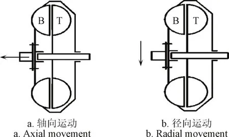
图2 叶轮振动示意图Fig.2 Schematic diagram of impeller vibration
1.2 模型建立
根据实际流域建立液力耦合器的流道模型和网格模型如图3、图4所示。考虑振动时计算域发生振动液力偶合器流动计算域将会有变化,在使用FLUENT进行数值计算时需要使用到动网格技术。由于流域边界变化主要发生在泵轮与涡轮交界处,设置分界面将完整模型划分为3个独立的网格模型,并设置分界面为interface,通过分界面传递数据[21-23]。

图3 流道模型Fig.3 Channel model of hydraulic coupling

图4 模型网格Fig.4 Grid model
泵轮和涡轮流道部分采用结构化六面体网格,单元数量少,计算速度快,结果可靠。边界运动域采用非结构网格以便FLUENT软件实现边界运动域计算,同时考虑到边界运动域计算域体积相对较小,进行网格划分的时候,为了提高计算精度和效率,选择较小的网格尺寸比例因子实现网格加密,以保证边界运动域网格足够精细[24-26]。
模型相关设置如表 2所示,考虑到流体体积法(volume of fluid,VOF)模型难以收敛,耗时较长,计算量大等特点,采用变时间步长法,设置柯朗数(Courant number)等于 0.25[27-28],即保证其计算精度同时缩短计算所需时间。

表2 模型参数Table2 Model parameters
1.3 试验测试系统
为了得到液力耦合器的特性曲线,选用充液量q分别为 40%、60%和 80%的工况点进行样机性能试验,试验台主要由电动机、增速齿轮箱、测量装置、减速齿轮箱,齿轮泵以及其他零部件所组成,设计试验台简图如图5a所示,试验台实物图如图5b所示,试验台主要针对样机进行试验,由于液力耦合器额定转速较高,需通过齿轮箱增速连接泵轮输入端,涡轮输出需通过减速齿轮减速再接齿轮泵加载。考虑到液力耦合器振动主要原因[10]是由不平衡与装配时不对中所引起的,因此为减小振动的发生,对泵轮与涡轮的动平衡进行校核。液力耦合器与连接件不对中,也是导致振荡因素之一,因此对增速箱-液力耦合器-减速箱进行重新找正,具体数据见表3和表4,通过校核使不对中和不平衡到达许用范围[7]。同时采用高精度电涡流传感器来对转子的轴向、径向位移进行检测,确保转矩测量过程中液力耦合器在技术要求范围内工作,通过上述检测和校核方法即认为可忽略液力耦合器振动影响,同时采集液力耦合器同一工况条件 10组数据取平均值,即得到文中试验数据[29-30]。

图5 样机试验Fig.5 Prototype test

表3 旋转组件校核前后的数据Table3 Data before and after verification of rotating components
2 计算结果及分析
2.1 数值与试验对比
为了验证 CFD混合模型和流体体积法(volume of fluid,VOF)模型的准确性,首先通过台架试验测量了液力耦合器正常工作条件(即不对中和动平衡在技术要求许可范围内)、充液量q为40%、60%和80% 时液力偶合器同步工况附近的泵轮转矩值,然后将CFD计算的相应工况点的数值与试验结果进行比较,结果如图6所示,可见VOF计算所得传递扭矩大小与相应试验值基本吻合,二者误差在 5%以内,证明所建立的液力耦合器两相流计算模型是准确的,同时可以发现,基于混合模型计算的结果误差大于10%,因此后续对振动条件下液力耦合器数值计算均采用VOF模型计算,以提高结论的可靠性。
2.2 流场计算结果及分析
数值计算中设定转速比i= 0.94、泵轮转速nB=n0(设定n0=10 000 r/min),对式(2)取振幅A=0.02 mm、相位角α=π/2、f= f0(旋转基频f0=1 047.2 Hz),即振动速度随时间作正弦变化,另通过用户自定义函数描述泵轮轴向和径向的运动速度,通过式(1)、式(3)即可得到轴向和径向位移和加速度。
循环圆面 A(即液力耦合器的轴面,左侧为泵轮流道、右侧为涡轮流道,图 7中上部为循环圆外径、下部为循环圆内径)内两相分布如图7a所示(红色部分为气相,蓝色部分为液相),泵轮轴向和径向振动两相界面分布基本与无振动条件相分布规律相同,而泵轮径向振动导致泵轮两相界面分布处沿径向方向气液混合现象增加,气相与液相分界面清晰度降低,同时由于径向运动导致涡轮产生小流量脉动,交界面向涡轮流道倾斜的幅度较小。轴向振动条件下因振动方向与流道内液体相对速度相同,对液流产生扰动,泵轮轴向振动导致泵轮两相界面明显泵轮内的气液分界面向泵轮出口处移动,且交界面向涡轮流道倾斜的幅度增加,开始出现流量脉动幅度增加的现象。

图7 A面流场分布Fig.7 Flow distribution of A surface
循环圆面A内压力分布如图7b所示。泵轮轴向和径向振动两相界面分布基本与无振动条件压力分布规律相同,离心力占主导地位,压力随着半径增加而增大。但泵轮径向振动导致泵轮内液体沿径向运动速度增加,泵轮外缘压力增加。泵轮轴向振动导致泵轮压力在两轮交界处有明显凸起,且交界面向涡轮流道倾斜的幅度增加,流量脉动导致压力脉动。
循环圆面A内流线分布如图7c所示(红色部分为气相,蓝色部分为液相),泵轮与涡轮间的滑差较小,环流形态为小环流。因计算给定振动速度相对于液流在离心力作用下环流速度相比较小,故轴向、径向振动条件下流线分布与无振动条件基本相同。
2.3 不同振动方向条件输出特性曲线
设定式(2)中A=0.02 mm,α=π/2,f=f0,截取3个整周期的外特性数据绘制曲线如图 8所示(为方便比较文中涡轮力矩、轴向力、径向力均设定计算方向相反)。设定泵轮(输入)扭矩大小TB约等于B0+ABsin(ω1t+α1),涡轮(输出)扭矩大小TT约等于T0+ATsin(ω2t+α2)。可以看出无振动条件下泵轮和涡轮力矩大小相等方向相反,且脉动幅值较小。径向振动条件下B0略大于T0,波动幅值A1约AT的3倍且α1=α2+π/2,周期ω相同。与无振动条件相比,径向振动条件涡轮力矩脉动幅值AT大小与无振动条件大致相等,B0减小4%,T0减小4.5%即代表传递效率下降。

图8 不同振动方向动态转矩曲线Fig.8 Dynamic torque curve under different vibration directions
径向振动条件下径向振动条件下MB略大于MT,波动幅值AB近视与AT相等且α1=α2无相位差,周期ω相同。与无振动条件相比,径向振动条件涡轮力矩脉动幅值A2大小与无振动条件大致相等,B0减小约5%与T0减小约6.5%。与径向条件规律相同,轴向振动会导致输入和输出力矩减小,即做功能力下降,且相同振幅A下轴向振动对做功能力影响比径向大。
产生原因为径向振动条件下扰动方向垂直于气液分界面此时扰动虽然能在耦合器泵轮内部形成较大的波峰,但是受泵轮内离心力影响,波峰会快速减小,因此涡轮内流量脉动较小即力矩变化较小。而轴向振动条件下振动方向与环流方向相同或者相反,因此会有效加强流量脉动造成较大的扰动从而引起涡轮力矩较大的波动。
2.4 不同转速条件输出特性曲线
为研究轴向振动对脉动影响,设定较大振幅A=0.04 mm、α=π/2、f=a、不同转速条件外特性曲线如图9a所示。从图9a中可以不同转速下B0近似与n02成正比,这与理论计算结果相同,且随着转速增加,泵轮涡轮转矩波动幅值增加。nB=2 500 r/min时幅值AB约为5 N·m,nB=5 000 r/min时幅值AB约为7 N·m,nB=10 000 r/min时幅值AB约为10 N·m。即AB增加比例小于对应转速增加比例。产生原因为转速较低时环流速度较小,轴向振动对力矩变化起主导作用。当转速较高时环流速度较大,环流和轴向振动共同影响下,也是导致0~0.0003 s内力矩波动的一个重要因素。

图9 不同转速条件特性曲线Fig.9 Characteristic curves under different rotation speeds
不同转速条件轴向力曲线如图9b所示,可见轴向力的大小随着转速增加而增加,其波动幅值基本保持在1 000 N左右,根据式(3)可计算得到其加速度大小,进而可求解得到速度大小。产生该现象的原因是高转速比时环流较弱,壳体上作用的轴向振动对轴向力变化起主导作用。
不同转速条件径向力曲线如图9c所示,径向力的大小随着转速增加,波动幅值略有增加,因轴向振动方向与径向力方向垂直故整体上轴向振动对径向力影响较小。
2.5 不同频率相同振动位移条件输出特性曲线
取α=π/2,A=0.02 mm,不同频率相同振幅条件下外特性曲线如图10所示,可以看出f=0.5f0时泵轮力矩波动幅值约为2.1 N·m,涡轮力矩波动幅值约为1.5 N·m。f=f0时泵轮力矩波动幅值约为1.3 N·m,涡轮力矩波动幅值约为1.2 N·m,f=2f0时泵轮力矩波动幅值约为1 N·m,涡轮力矩波动幅值约为0.6 N·m。可以看出振动频率越大,泵轮转矩波动范围增加且泵轮涡轮振幅偏差增加。

图10 不同振动周期条件动态转矩曲线Fig.10 Dynamic torque curve under different vibration periods
2.6 不同振幅条件输出特性曲线
取α=π/2、f=f0,计算得到转矩随时间变化曲线如图11a所示,从图11a中可以振幅A增加则转矩振幅AB增加,B0下降,特别是当振幅A=0.05 mm时,液力耦合器转矩波动范围超过 30%且转矩存在明显跌落,这表明振幅达到一定程度对液力耦合器流动扰动作用明显增加,即过大的轴向振幅造成液力耦合器流量脉动幅值急剧增加,做功能力降低。
轴向力随时间变化曲线如图 11b所示,振幅A=0.04 mm条件下液力耦合器力矩波动不超过0.5%,因轴向力波动主要由轴向振动引起的,故此时轴向力脉动与振动加速度成正比。当振幅A=0.05 mm时液力耦合器轴向力输出不太稳定,结合图11a转矩跌落情况可以表明此时液流流量脉动较大,液力耦合器内部环流形态发生较大改变。
振幅A分别取0、0.01、0.02、0.03、0.04、0.05、0.06 mm,通过拟合得到泵轮力矩幅值AB与振幅A、泵轮力矩平均值B0随A关系如图11c所示,从图中可以看出,随着振幅增加转矩波动幅值减小,即此时振动对液力耦合器流场影响较小。A>0.04 mm时转矩波动范围曲线急剧增加,且存在明显的降幅。而振幅A≤0.02 mm时,液力耦合器转矩波动不超过2%且转矩降幅较小。对于该液力耦合器来说,从控制液力耦合器内部稳定状态及减少其转矩波动及轴向力的角度,轴向允许的波动幅值小于 0.02 mm较为合适,即对应轴向窜动值小于0.04 mm。

图11 不同振幅条件特性曲线Fig.11 Characteristic curves under different amplitudes
3 结 论
1)振动会导致传递转矩下降,且轴向振动对传递转矩影响较大、对径向力影响较小。
2)旋转基频附近,随着振动频率的增加,泵轮、涡轮转矩脉动幅度增加,且泵轮转矩脉动幅度增加量大于涡轮。
3)振动会导致泵轮、涡轮转矩产生波动,其脉动幅值随着振动振幅增加而增加,且当振幅>0.04 mm时转矩脉动幅值急剧增加,振幅≤0.02 mm时转矩脉动幅值变化不太明显。从控制液力耦合器内部稳定状态及减少其转矩波动及轴向力的角度,轴向允许的波动幅值小于0.02 mm较为合适,即对应轴向窜动值小于0.04 mm。
[1] 初长祥,马文星. 工程机械液压与液力传动系统(液力卷)[M].北京:化学工业出版社,2015.
[2] 杨贵华. 液力传动节能装置:液力偶合器、液黏调速离合器[M]. 北京:化学工业出版社,2010.
[3] 刘应诚. 液力偶合器实用手册[M]. 北京:化学工业出版社,2008.
[4] 伍川勇.液力耦合器振动的原因分析[J]. 风机技术,2011(2):67-69. Wu Chuanyong. Analysis of causes on hydraulic coupling vibration[J]. Wind Turbine Technology, 2011(2): 67-69. (in Chinese with English abstract)
[5] Jia Xiaoqi, Cui Baoling, Zhang Yuliang, et al. Study on Internal flow and external performance of a semi-open impeller centrifugal pump with different tip clearances[J]. International Journal of Turbo & Jet-Engines, 2014(5): 2191-2197.
[6] 柴博森,马文星,卢秀泉,等. 基于粒子跟踪测速技术的液力耦合器内部流速测定方法[J]. 农业工程学报,2011,27(7):140-145. Chai Bosen, Ma Wenxing, Lu Xiuquan, et al. Internal flow velocimetry of hydraulic coupling based on particle tracking velocimetry technology[J]. Transactions of the Chinese Society of Agricultural Engineering (Transactions of the CSAE), 2011, 27(7): 140-145. (in Chinese with English abstract)
[7] 柴博森,马文星,刘春宝. 基于互相关算法的液力偶合器内部流场分析[J]. 农业机械学报,2011,42(12):38-42. Chai Bosen, Ma Wenxing, Liu Chunbao. Analysis of internal flow field in hydrodynamic coupling based on crosscorrelation algorithm[J]. Transactions of the Chinese Society for Agricultural Machinery, 2011, 42(12): 38-42. (in Chinese with English abstract)
[8] 柴博森,王玉建,刘春宝,等. 基于粒子图像测速技术的液力变矩器涡轮内流场测试与分析[J]. 农业工程学报,2015,31(12):92-97. Chai Bosen, Wang Yujian, Liu Chunbao, et al. Test and analysis of internal flow field in turbine of hydrodynamic torque converter based on particle image velocimetry[J]. Transactions of the Chinese Society of Agricultural Engineering (Transactions of the CSAE), 2015, 31(12): 92-97. (in Chinese with English abstract)
[9] 范丽丹,马文星,柴博森,等. 液力耦合器气液两相流动的数值模拟与粒子图像测速[J]. 农业工程学报,2011,27(11):66-70. Fan Lidan, Ma Wenxing, Chai Bosen, et al. Numerical simulation and particle image velocimetry for gas-liquid two-phase flow in hydraulic couplings[J]. Transactions of the Chinese Society of Agricultural Engineering (Transactions of the CSAE), 2011, 27(11): 66-70. (in Chinese with English abstract)
[10] 何延东,马文星,刘春宝. 液力偶合器部分充液流场数值模拟与特性计算[J]. 农业机械学报,2009,40(5):24-28. He Yandong, Ma Wenxing, Liu Chunbao. Numerical simulation and characteristic calculation of hydrodynamic coupling[J]. Transactions of the Chinese Society for Agricultural Machinery, 2009, 40(5): 24-28. (in Chinese with English abstract)
[11] 何延东,马文星,邓洪超,等. 基于 CFD 的调速型液力耦合器设计方法[J]. 农业机械学报,2010,41(6):31-36. He Yangdong, Ma Wenxing, Deng Hongchao. Design method of variable speed hydrodynamic coupling based on CFD[J]. Transactions of the Chinese Society for Agricultural Machinery, 2010, 41(6): 31-36. (in Chinese with English abstract)
[12] Mirsepassi A, Rankin D D. Particle image velocimetry in viscoelastic fluids and particle interaction effects[J]. Experiments in Fluids, 2014, 55(1): 1-7.
[13] 郭枭,李春丽,邱广明,等. 基于粒子图像测速技术的近膜面流场特性[J]. 农业工程学报,2015,31(1):91-97. Guo Xiao, Li Chunli, Qiu Guangming, et al. Characteristics of flow field near membrane surface based on particle image velocimetry technology[J]. Transactions of the Chinese Society of Agricultural Engineering (Transactions of the CSAE), 2015, 31(1): 91-97. (in Chinese with English abstract)
[14] 余国保,周云波. 基于大涡模拟法的液力缓速器内流场仿真分析[J]. 机械工程与自动化, 2014(1):52-54. Yu Guobao, Zhou Yunbo. Internal flow field analysis based on large eddy simulation for hydrodynamic retarder[J]. Mechanical Engineering & Automation, 2014(1): 52-54. (in Chinese with English abstract)
[15] Luo Y, Feng L H, Liu S H, et al. Numerical comparisons of the performance of a hydraulic coupling with different pump rotational speeds[C]//IOP Conference Series: Materials Science and Engineering, 2013: 257-260.
[16] Luo Y, Zuo Z G, Liu S H, et al. Numerical simulation of the two-phase flows in a hydraulic coupling by solving VOF model[C]//IOP Conference Series: Materials Science and Engineering, 2013: 668-672.
[17] Huitenga H, Mitra N K. Improving startup behavior of fluid couplings through modification of runner geometry: Part 2: Modification of runner geometry and its effects on the operation characteristics[J]. ASME Journal of Fluids Engineering, 2000, 122(4): 689-693.
[18] Sinibaldi E, Beux F, Salvetti M V. A numerical method for 3D barotropic flows in turbomachinery[J]. Flow, Turbulence and Combustion, 2006, 76(4): 371-381.
[19] Hampel U, Hoppe D, Diele K H, et al. Application of ga mma tomography to the measurement of fluid distributions in a hydrodynamic coupling[J]. Flow Measurement and Instrumentation, 2005, 16(2): 85-90.
[20] 何延东. 基于 CFD的大功率调速型液力偶合器设计[D].长春:吉林大学,2009. He Yandong. Design of Variable Speed High-power Hydrodynamic Coupling Basen On CFD[D]. Changchun: Jilin University, 2009. (in Chinese with English abstract)
[21] 石宝龙,岂兴明,矫津毅,等. 二次流与叶顶间隙损失的数值研究[J]. 航空动力学报,2009,24(5):1096-1100. Shi Baolong, Qi Xingming, Jiao Jinyi, et al. Numerical analysis of the secondary flow and tip clearance leakage loss[J]. Journal of Aerospace Power, 2009, 24(5): 1096-1100.(in Chinese with English abstract).
[22] Lu Xiuquan, Ma Wenxing, Fan Lidan, et al. Visualization experiment with PIV and analysis of flow field in hydrodynamic coupling[C]//2010 International Conference on Applied Mechanics and Mechanical Engineering, Clausthal-Zellerfeld, Trans Tech Publications, Germany, 2010: 1327-1333.
[23] Charles N M, Danamichele B. Hydraulic analysis of a reversible fluid coupling[J]. Journal of Fluids Engineering, 2002, 123(2): 249-255.
[24] Huitenga H, Mitra N K. Improving startup behavior of fluid couplings through modification of runner geometry: partⅠ-fluid flow analysis and proposed improvement[J]. Journal ofFluids Engineering, 2000, 122(4): 683-688.
[25] Magagnato F, Pritz B, Gabi M. Calculation of the VKI turbine blade with LES and DES[J]. Journal of Thermal Science, 2007, 16(4): 321-327.
[26] Tauro F, Porfiri M, Grimaldi S. Orienting the camera and firing lasers to enhance large scale particle image velocimetry for streamflow monitoring[J]. Water Resources Research, 2014, 50(9): 7470-7483.
[27] Gao Qi, Wang Hongping, Shen Gongxin. Review on development of volumetric particle image velocimetry[J]. Chinese Science Bulletin, 2013, 58(36): 4541-4556.
[28] Debesse P, Carlès D B, Lusseyran F, et al. Oscillating and streaming flow identification in a thermoacoustic resonator, from undersampled PIV measurements[J]. Measurement Science and Technology, 2014, 25(2): 025005.
[29] Charonko J J, Vlachos P P. Estimation of uncertainty bounds for individual particle image velocimetry measurements from cross-correlation peak ratio[J]. Measurement Science and Technology, 2013, 24(6): 065301.
[30] Westerweel J, Elsinga G E, Adrian R J. Particle image velocimetry for complex and turbulent flows[J]. Annual Review of Fluid Mechanics, 2013, 45(1): 409-436.
Characteristics of high speed hydraulic coupler under pump wheel axial vibration conditions
Su Huashan, Chen Congping※, Zhao Meiyun, Gao Zhenjun, Yu Wan, Zhang Yangjun
(1.Hubei Key Laboratory of Hydroelectric Machinery Design & Maintenance, China Three Gorges University, Yichang443002,China; 2.College of Mechanical & Power Engineering of China Three Gorges University, Yichang443002, China)
Hydrodynamic coupler is used for startup tool in the large inertia mechanical equipment. The incomplete neutrality of impeller installation and loading perturbation cause the input shaft of pump wheel to vibrate. Internal flow characteristics of hydrodynamic coupler are affected by the vibration of the pump wheel. And the external performance of hydrodynamic coupler is determined by its distribution of internal flow field. Therefore, it is very important to make a deep research on the distribution of internal flow field under the condition of vibration. Numerical simulation is a main way to study the internal flow field of hydrodynamic coupler. The simulation physical model was created firstly by using the software of ICEM (integrated computer engineering and manufacturing), and hexahedron and tetrahedron cells were used to partition the calculation region to generate the grids. The hexahedron was used in main channel of pump wheel and turbine. The tetrahedron was used in boundary motion region. And then the software of FLUENT was used to perform the simulation. The UDF (user-defined function) of FLUENT was used to define the parameters of dynamic mesh control, as well as the axial velocity of pump. Realizable k-ε model was used, besides, the turbulence model and the second-order upwind scheme were adopted for solving the momentum and kinetic energy equation, and the PISO (pressure-implicit with splitting of operators) algorithm was used for pressure and velocity coupling. With the pump axial moving, the boundary of the corresponding flow field would change. The dynamic mesh model was used for boundary motion domain caused by vibration. The results of numerical simulation that are calculated by different two-phase flow models were quite different. In order to obtain accurate and reliable results of numerical simulation, the numerical simulation and external characteristic experimental results were compared. It showed that the error of VOF (volume of fluid) model was less than 5%, and the error of Mixture model was over 20%. It showed that the simulation results by VOF models were more accurate and close to the experimental results. Furthermore, the external characteristics and phase distribution law of fluid coupling were also compared and analyzed under different axial vibration status. And the results indicated that the vibration of the pump wheel could make the flow pulsation increase. Under the condition of radial vibration, the disturbance direction was perpendicular to the gas-liquid interface. A larger wave crest could be formed within pump wheel. However, due to the centrifugal force in the pump wheel, the wave would rapidly decrease. Therefore, the flow pulsation in the turbine was relatively small, that was to say, the torque change was relatively small. Under the condition of axial vibration, the direction of vibration was the same or opposite to the direction of circulation. Therefore, it would effectively enhance the fluctuation of the flow pulsation and cause the larger fluctuation of turbine torque. Numerical calculation showed that the higher the rated speed, the larger the torque ripple amplitude of pump turbine and the fluctuation range of radial force and axial force. The vibration period decreased and the deviation of the torque ripple of the pump turbine was bigger. Vibration would lead to the decrease of the transmission torque, and the axial vibration had a greater impact on the transmission torque, and a smaller influence on the radial force. The vibration would cause the pump wheel and turbine torque to fluctuate, and the pulsation amplitude increased with the increase of the vibration amplitude. When the amplitude of vibration was less than 0.02 mm, the amplitude of torque was smaller. But when the amplitude of vibration was 0.04 mm, the amplitude of torque increased sharply. On that basis, the axial clearance value should not be more than 0.04 mm (the axial clearance was twice of the amplitude of vibration).
computer simulation; visualization; models; hydraulic coupling; axial vibration; two-phase flow
10.11975/j.issn.1002-6819.2017.07.007
TH137.331
A
1002-6819(2017)-07-0051-07
2016-09-27
2017-04-10
国家自然基金(51475266,51605254);水电机械设备设计与维护湖北省重点实验室(三峡大学)开放基金(2016KJX03);宜昌市科技局项目(A14-302-a03)
苏华山,男,博士,讲师,主要从事流体机械内部流动特性研究。宜昌 三峡大学水电机械设备设计与维护湖北省重点实验室,443002。
Email:suhuashan@ctgu.edu.cn
※通信作者:陈从平,男,博士,教授,主要从事流体动力学方面的研究。宜昌 三峡大学水电机械设备设计与维护湖北省重点实验室,443002。
Email:mechencp@163.com