设计流量和土壤质地对微孔陶瓷灌水器入渗特性的影响
2017-05-27蔡耀辉吴普特朱德兰陈俊英
蔡耀辉,吴普特,※,张 林,朱德兰,3,陈俊英,3,杨 帆
(1. 西北农林科技大学水利与建筑工程学院,杨凌 712100;2. 西北农林科技大学水土保持研究所,杨凌 712100;3. 西北农林科技大学中国旱区节水农业研究院,杨凌 712100)
设计流量和土壤质地对微孔陶瓷灌水器入渗特性的影响
蔡耀辉1,吴普特1,2,3※,张 林2,3,朱德兰1,3,陈俊英1,3,杨 帆1
(1. 西北农林科技大学水利与建筑工程学院,杨凌 712100;2. 西北农林科技大学水土保持研究所,杨凌 712100;3. 西北农林科技大学中国旱区节水农业研究院,杨凌 712100)
为探明微孔陶瓷灌水器土壤中入渗流量变化的原因,明确微孔陶瓷灌水器的出流原理,该研究基于土桶模拟试验,研究3种设计流量(0.72、1.87和4.40 L/h)的微孔陶瓷灌水器下2种土壤(黄绵土、塿土)的渗流特性。结果表明,使用不同灌水器灌溉后,短时间内入渗流量均迅速减小,而后缓慢减小趋于稳定。设计流量与土壤质地均影响灌水器的出流。灌水器周围土壤水势的变化是造成入渗流量变化的直接原因,土壤含水率的变化是入渗流量变化的根本原因。在没有淹没出流的情况下,土壤含水率越高,入渗流量越小。设计流量为1.87 L/h灌水器应用于塿土中,当土壤含水率由13%增大至40%时,入渗流量由1.4 L/h下降至0.3 L/h左右。灌水器周围土壤含水率对入渗流量具有反馈调节作用。采用微孔陶瓷灌水器作为灌溉系统的核心部件,在内部水头适宜(微压或零压)的情况下,通过灌水器入渗流量与土壤含水率的耦合作用,可实现土壤水分的自动调控,达到主动灌溉的目的。该文可为微孔陶瓷灌水器的推广应用提供参考。
质地;土壤;含水率;微孔陶瓷灌水器;流量;水势
蔡耀辉,吴普特,张 林,朱德兰,陈俊英,杨 帆. 设计流量和土壤质地对微孔陶瓷灌水器入渗特性的影响[J]. 农业工程学报,2017,33(7):100-106.doi:10.11975/j.issn.1002-6819.2017.07.013 http://www.tcsae.org
Cai Yaohui, Wu Pute, Zhang Lin, Zhu Delan, Chen Junying, Yang Fan. Effects of designed flow rate and soil texture on infiltration characteristics of porous ceramic irrigation emitters[J]. Transactions of the Chinese Society of Agricultural Engineering (Transactions of the CSAE), 2017, 33(7): 100-106. (in Chinese with English abstract)doi:10.11975/j.issn.1002-6819.2017.07.013 http://www.tcsae.org
0 引 言
微孔陶瓷灌水器是一种造价低廉、性能优良的新型灌水器,其利用微孔陶瓷作为渗水介质对灌溉水进行消能,直接向作物根部供水[1-4]。与常规滴灌技术相比,具有节水、节能等优点,适宜在干旱和半干旱地区推广应用[5-6]。
作为一种新型的地下灌水器,有关微孔陶瓷灌水器土壤中渗流特性的研究较少[7-11]。徐增辉等[12]研究发现,2 m工作水头下,免烧微孔陶瓷灌水器在黏壤土中的入渗流量随着灌水历时的增加逐渐趋于稳定。任改萍等[13-14]研究发现,供水水头越大,微孔陶瓷渗灌初始阶段的入渗流量越大,相同时间的累计入渗量也越大。Gupta等[15]研究发现,土壤质地对多孔黏土管的入渗流量影响较为显著,土壤的饱和导水系数越大,多孔黏土管的入渗流量较空气中设计流量增长幅度越大;同时在低水头下,土壤毛细管力对多孔黏土管的入渗流量影响较大,但在高水头下影响可以忽略不计。谷川寅彦等[16]研究发现,在砂质黏壤土中、0.2 m工作水头下,多孔素烧管的透水系数(设计流量)越大,累计灌水量越大;一定灌水量情况下,透水系数大可有效降低系统的工作水头,同时可以发挥灌溉系统的自调节作用。上述研究分别对不同条件下陶瓷灌水装置在土壤中的渗流特性进行了分析,但对影响陶瓷灌水装置入渗流量的主要原因分析不透彻。因此本研究的目的在于通过研究不同条件下微孔陶瓷灌水器的渗流规律,分析微孔陶瓷灌水器入渗流量变化的主要原因,进而明确微孔陶瓷灌水器工作原理。
本研究基于室内定容重土桶模拟试验,研究 3种设计流量(灌水器在空气中设计水头下的流量)的微孔陶瓷灌水器在 2种土壤中的渗流特性,分析灌水器入渗流量和周围土壤含水率随时间的变化规律,并通过灌水器周围土壤水势变化对灌水器入渗流量和含水率变化规律进行解释,旨在为微孔陶瓷灌水器的推广应用奠定基础。
1 材料与方法
1.1 试验装置与土样
试验在西北农林科技大学中国旱区节水农业研究院灌溉水力学试验大厅进行。试验装置由土桶、马氏瓶、排气稳压管、灌水器和土壤水分传感器组成(图 1a)。土桶规格为37 cm×29 cm×42 cm(上直径×下直径×高)。土桶上有直径为 20 mm的对称小孔(距离土桶上边缘16 cm)用以通过进水管。供水装置为马氏瓶,其直径为15 cm,高为66 cm。灌水器通过聚氯乙烯三通与输水管道相连接,垂直埋置于土桶中,埋深为20 cm。灌水器采用西北农林科技大学中国旱区节水农业研究院研制的砂基微孔陶瓷灌水器(图1b)。灌水器为圆柱形腔体结构,以石英砂、滑石粉、糊精和硅溶胶为主要原料烧结而成,灌水器陶瓷材料内部均匀分布着孔径为10~100 μm的微孔,可实现灌溉水的消能与运移。灌水器的结构参数与性能参数如表1所示。设计流量为空气中0.2 m水头下的测定值。
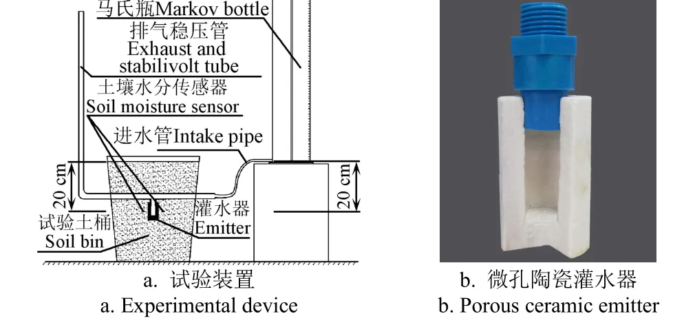
图1 试验装置与微孔陶瓷灌水器示意图Fig.1 Schematic of experimental device and porous ceramic irrigation emitter
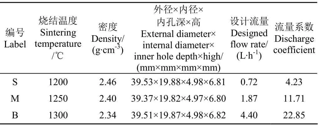
表1 试验用灌水器特征参数Table1 Characteristic parameter of emitters used in experiment
试验选择塿土和黄绵土 2种不同类型的土壤。塿土取自陕西渭河三级阶地小麦田,黄绵土取自陕西省榆林市清涧县店则沟镇红枣林地;取土深度均为30 cm,将取得的试验土壤风干、碾压、混合后过2 mm筛网分别留样。土壤颗粒组成采用激光粒度分析仪(MS2000型,马尔文,英国)测定,土壤饱和导水率利用土壤颗粒组成和容重,采用RETC软件进行估算,结果如表2所示。土壤水分特征曲线采用高速冰冻离心机(CR21G PF型,日立,日本)测定,结果如图2所示。

表2 试验所用土壤的物理性能指标Table2 Summary of physical properties for tested soils
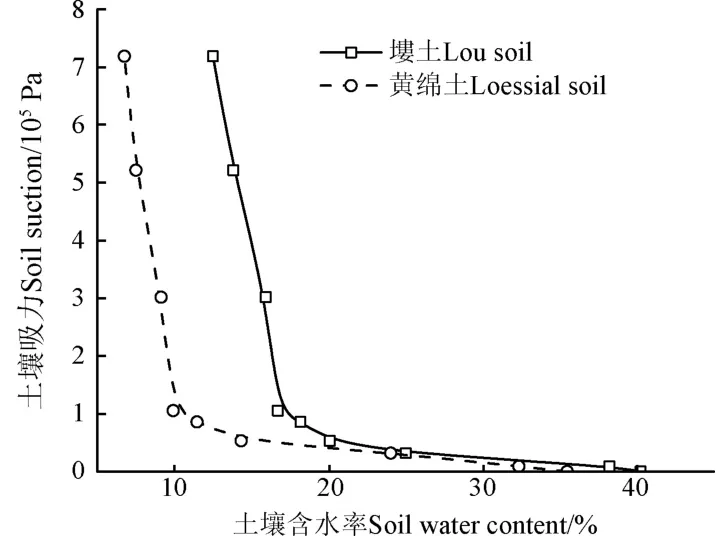
图2 塿土与黄绵土水分特征曲线Fig.2 Soil water characteristic curves of lou soil and loessial soil
1.2 试验方法与测定内容
本试验包括灌水器设计流量和土壤质地 2个因素。应用3种不同设计流量的灌水器(S型、M型、B型)分别在 2种土壤(塿土、黄绵土)中进行入渗试验,试验共6个处理,各处理重复3次,共进行18组试验。将试验土样(容重为1.35 g/cm3;填土时风干塿土含水率为7%左右,风干黄绵土含水率为5%左右)分层(每层5 cm)装入土桶,分层界面处打毛,使土壤颗粒充分接触。试验装土深度为40 cm。土桶表面采用0.5 mm塑料薄膜覆盖,以减小土壤水分蒸发损失对试验的影响。灌水器工作水头通过马氏瓶出口与灌水器中心点处高差决定,为0.2 m。试验装置充满水后,立刻采用秒表记录灌水时间,同时记录灌水开始时刻(北京时间,与土壤水分传感器时刻一致);按照先2 min后10 min的原则,记录不同时刻马氏瓶的水位线。灌水时间达到5 h时停止供水,灌水器的入渗流量根据单位时间马氏瓶刻度和横截面积乘积计算,试验数据取3次重复的平均值,L/h。同时在灌水器中心点周围4 cm处均匀布置3个标定后的土壤水分传感器探头(EC-5型,Decagon,美国),间隔1 min测定土壤含水率,试验数据取3个探头所测得数据的平均值。
2 结果与分析
2.1 不同灌水器对土壤入渗的影响
图3为不同灌水器设计流量和土质条件下土壤累计入渗量与入渗流量在5 h内随时间的变化过程。从图3可以看出,不同处理下土壤累计入渗量随时间的变化较为类似。累计入渗量均随灌水时间增加而逐渐增大。相同灌水时间下同类型灌水器在黄绵土的累计入渗量明显大于塿土。相同灌水时间下,B型灌水器的累计入渗量最大,在5 h时黄绵土中为12.2 L,塿土中为8.8 L;M型灌水器的累计入渗量最小,在5 h时黄绵土中为3.65 L,塿土中为1.75 L。不同处理下灌水器入渗流量随时间的变化也较为类似。灌水器入渗流量随时间的变化趋势可分为 2个阶段:1)初始阶段(灌水0.5 h左右),灌水器的入渗流量随灌水时间的增加迅速减小;2)稳定阶段,随着灌水时间的继续增加,灌水器的入渗流量缓慢减小趋于稳定。但B型灌水器在黄绵土中的出流规律略有不同,在灌溉4 h后,灌水器的累计入渗量为10.4 L,造成土桶中灌水器下部已经完全饱和,进而淹没灌水器,此时灌水器相当于淹没出流,灌水器的累计入渗量越大,其周围的水位越高,因此在4 h后其入渗流量会出现明显的降低。
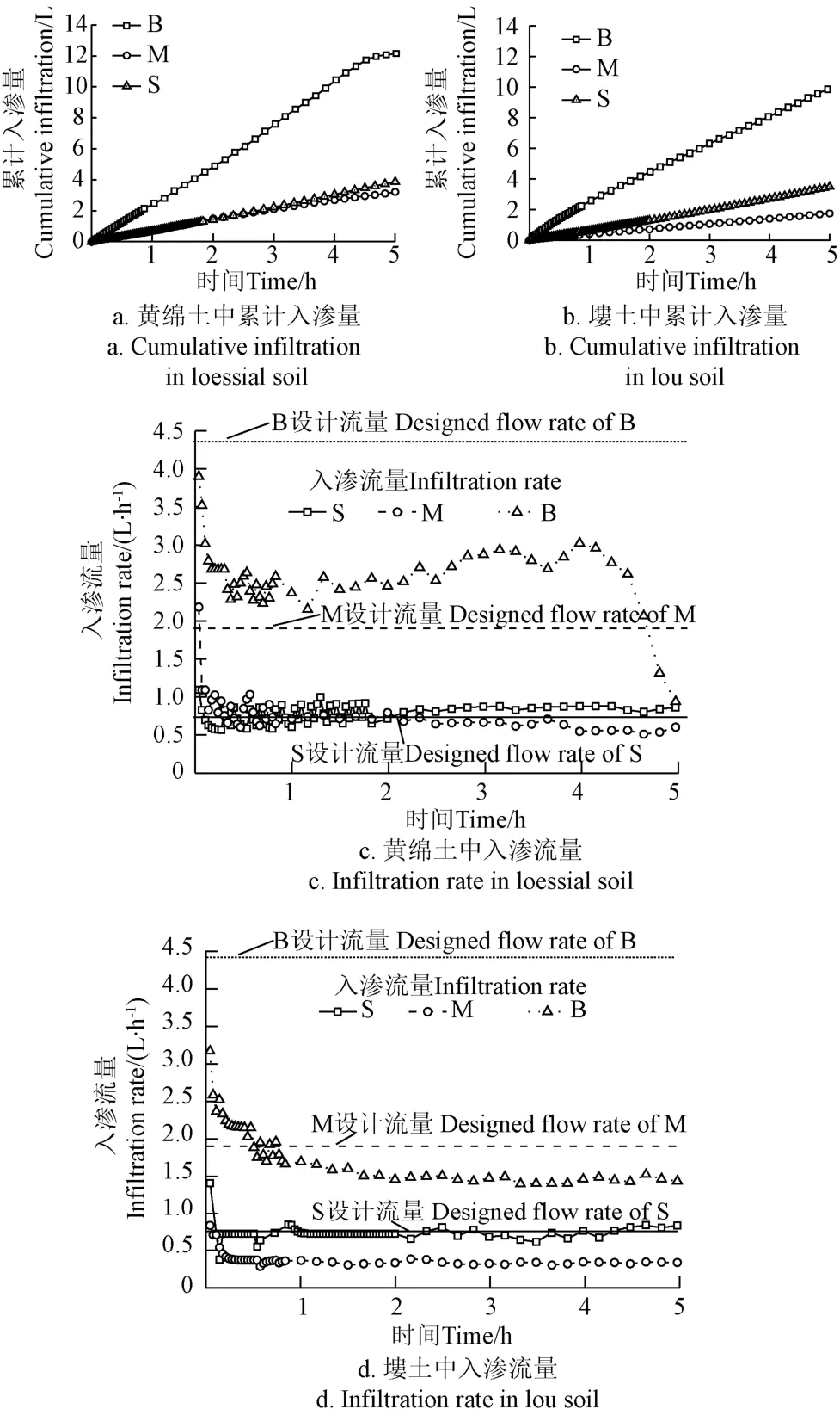
图3 不同灌水器设计流量和土壤类型条件下累计入渗量与入渗流量随时间的变化过程Fig.3 Cumulative infiltration and infiltration rate as function of time at emitter with different designed flow rate and soil type
表3为土壤平均入渗流量(0.5 h、5 h平均值)与灌水器设计流量。从表中看出,土壤类型会对入渗流量造成影响,黄绵土的入渗流量均大于塿土。设计流量对灌水器的实际出流有显著影响(P<0.05)。随着灌水器设计流量增大,灌水器在塿土中的平均入渗流量出现先减小后增大。

表3 灌水器设计流量与不同时段土壤入渗流量Table3 Designed flow rate of emitters and infiltration rate in soil at different time
2.2 微孔陶瓷灌水器周围土壤水势估算
谷川寅彦等[16]研究发现,灌水器入渗流量变化是灌水器内、外部水势差和微孔陶瓷渗透系数共同作用的结果。因此由Darcy定律可得[17]

式中Q为灌水器的入渗流量,L/h;k为微孔陶瓷的渗透系数,cm/h;H为灌水器内、外部水势差,m;A为灌水器的渗流面积,cm2;L为灌水器的渗流路径长度,cm;K为与灌水器结构尺寸、渗透系数有关的常数,称为流量系数,m2/h;H′为灌水器工作水头,m;φ为灌水器外部土壤水势,m。
因为流量系数K仅与灌水器结构尺寸、渗透系数有关,因此空气中和土壤中的流量系数保持不变。本研究中灌水器工作水头H′均为0.2 m。根据图3和式(1)计算得灌水器周围土壤水势如图4所示。由图4可以看出,灌水初期,灌水器周围的土壤水势迅速增大,随着灌水进行,土壤水势逐渐趋于稳定。土壤质地不同会对灌水器周围土壤水势造成影响。随着灌水器设计流量增大,灌水器周围的土壤水势出现先增大后减小的趋势。
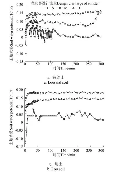
图4 不同设计流量和土质条件下灌水器周围土壤水势随时间的变化过程Fig.4 Soil water potential as a function of time at emitters with different design flow rates and soil types
结合表3可以看出,在2种土壤中,B型、M型灌水器的平均流量均小于灌水器的设计流量。这是由于 B型、M 型灌水器设计流量较大,在灌水器周围形成正压区[18-21],阻碍灌水器的出流,使得灌水器的入渗流量降低。由于 S型微孔陶瓷灌水器的设计流量较小,其设计流量接近于塿土的饱和导水率,小于黄绵土的饱和导水率。因此在塿土中,土壤对其出流的阻碍作用较小,因而其入渗流量与设计流量较为接近。但在黄绵土中,S型微孔陶瓷灌水器的入渗流量小于黄绵土的饱和导水率,微孔陶瓷灌水器周围逐渐湿润,土壤对灌水器出流的抑制作用尚不明显,因此其入渗流量稍大于设计流量。
2.3 微孔陶瓷灌水器周围土壤含水率随时间变化规律
图5为不同设计流量和土质条件下灌水器周围土壤含水率在300 min内随时间的变化过程。不同处理灌水器周围土壤含水率随时间的变化规律基本一致,略有差异。灌水器周围土壤含水率在短时间内迅速增加,接近饱和,B型灌水器周围土壤含水率增加速率最快,M型次之,S型最慢。灌水300 min时灌水器周围土壤含水率均接近于土壤饱和含水率。
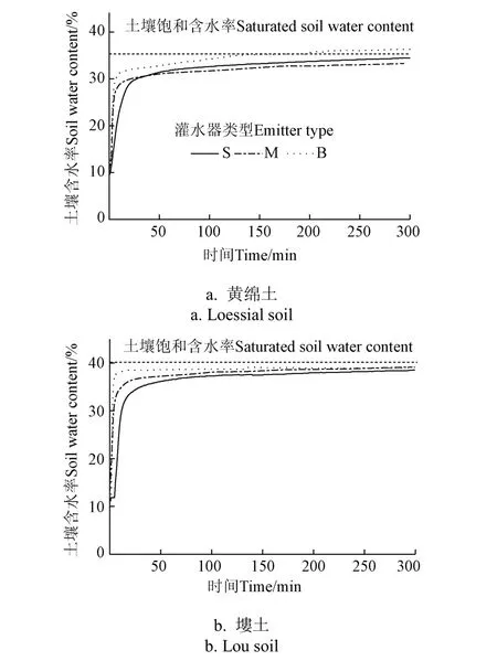
图5 不同设计流量和土质条件下灌水器周围土壤含水率随时间的变化过程Fig.5 Soil water contents around emitters as a function of time at emitters with different designed flow rates and soil types
结合图3~图5可以看出,初始阶段,灌溉水经由灌水器消能进入土壤,灌水器周围的土壤含水率由 10%以下迅速增长,导致灌水器周围土壤水势迅速由负压转变为零压和正压,因此土壤对灌水器的出流由促进作用迅速转变为抑制作用,使得灌水器入渗流量随时间迅速减小。稳定阶段,灌水器周围的土壤含水率趋于饱和,土壤水势变化较小,土壤水分扩散达到稳定阶段,灌水器的入渗流量基本维持稳定。
2.4 微孔陶瓷灌水器周围土壤水势与入渗流量的关系
灌水器周围土壤水势(150~300 min的平均值)与灌水器设计流量关系如图 6所示。随着设计流量增大,灌水器外部土壤水势逐渐向零压和正压转变,而后正压值出现先增大后减小的趋势。当灌水器的设计流量小于土壤的饱和导水率时,土壤对于灌水器的出流有促进作用,灌水器周围则以负压为主。当设计流量等于土壤的饱和导水率时,土壤对灌水器的出流无抑制作用,灌水器周围则以零压为主。当设计流量大于土壤的饱和导水率时,土壤对灌水器的出流有抑制作用,灌水器周围则以正压为主。当灌水器的设计流量远远大于土壤的饱和导水率时,灌水器周围的土壤水势仍为正压,但较为复杂。本研究预试验表明,当灌水器设计流量远远大于土壤的饱和导水率时,出流过程中,土壤水分会优先在大孔隙中形成通道,灌水器周围的土壤结构可能就会受到破坏,形成空穴,渗流通道等。此时若渗流通道与地表连通,则灌水器周围的正压就下降到与此处的重力势相等。若形成空穴,则灌水器周围的正压就与空穴内部自由水面与灌水器中心点的高差有关,称为积水深度[22]。
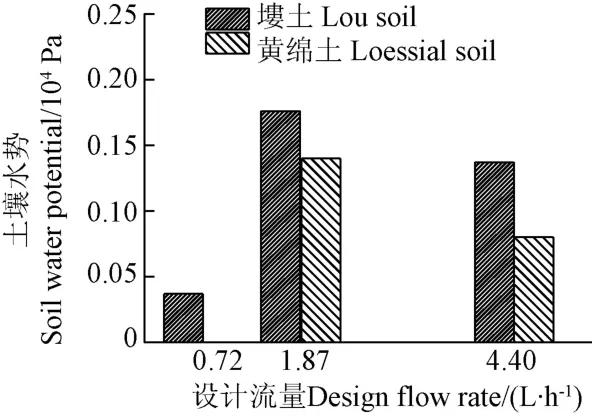
图6 灌水器设计流量与土壤水势关系Fig.6 Relationship between designed flow rate of emitter and soil water potential
国内外学者[23-27]对地下滴灌的研究中发现,地下滴灌灌水器周围的土壤水势一般高达0.5~4.0 m。这是因为地下滴灌所采用灌水器均为点源入渗,灌溉水经过灌水器消能后由灌水器出口进入土壤,水分主要在灌水器出口处聚集,因而会使得灌水器出口处出现较高的正压。这与本研究中灌水器周围土壤水势均未超过 0.2 m有显著区别。张书函等[28]在渗灌管的研究中,渗灌管的设计流量为0.79 L/(h·m),其入渗流量仅为0.06 L/h,该种情况下渗灌管周围土壤水势为负压。渗灌管可类比为7 cm长的微孔陶瓷灌水器,微孔陶瓷灌水器与渗灌管类似,均为非点源入渗,而是面源入渗。灌溉水经由灌水器中微孔消能后在整个灌水器外表面上与土壤接触,相对于地下滴灌,即使是设计流量较大的陶瓷灌水器(B型)在单点处流量也较小,因此形成正压比较低。而对于设计流量较小的陶瓷灌水器,灌水器周围土壤水势则为零压或负压。
综上,土壤水势的变化是灌水器入渗流量变化的直接原因。随着设计流量增大,土壤对灌水器的出流由促进逐渐转变为抑制,抑制能力则会出现先增大后减小的趋势。因此,在同一土壤中,随着设计流量增大,由于土壤水势的作用,灌水器在土壤中的平均流量会出现先减小后增大的趋势。
2.5 微孔陶瓷灌水器入渗流量与土壤含水率的耦合关系
图7为不同处理下灌水器周围含水率与入渗流量的关系曲线。从图中可以看出,各处理灌水器入渗流量均随着含水率的增大而减小。以塿土中M型灌水器为例,当土壤含水率由13%增大至40%时,灌水器入渗流量由1.4 L/h下降至0.3 L/h左右,土壤含水率的增加使得土壤水势由负压逐渐转变为正压,因而对灌水器出流也由促进转变为抑制,使得灌水器的入渗流量逐渐降低。在没有淹没出流的情况下(如黄绵土中B型灌水器 240 min后),土壤含水率越高,灌水器的入渗流量也就越小。灌水器周围土壤含水率对灌水器入渗流量具有反作用。
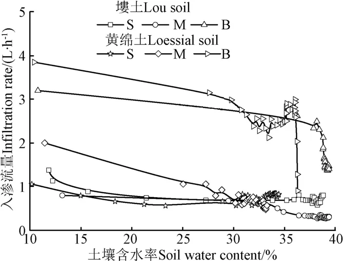
图7 不同灌水器在土壤中的入渗流量与周围含水率关系Fig.7 Relationships between flow rate of different emitters in soil and soil water content around emitters
灌水器土壤中入渗流量发生变化的直接原因是土壤水势的变化,但根本原因在于土壤含水率的变化。雷廷武等[29-32]利用陶土头进行负压灌溉的试验结果表明,只需要灌水器内部水头大于外部水势,灌溉水即可由灌水器流入土壤;灌水器停止出流的条件为内部水头等于外部水势。在负水头条件下,该工况较易出现。当灌水器内部工作水头为正,灌水器外部土壤水势为正压;或者当灌水器内部工作水头为0,灌水器外部土壤水势为0,均可使灌水器停止出流。本研究中,当 S型灌水器内部水头为0,随着灌溉进行,灌水器周围土壤达到饱和,土壤水势为0,此时灌水器就会停止出流。当M型灌水器内部水头为小于0.2 m的某一正值,随着灌溉进行,灌水器周围土壤达到饱和,土壤水势为正值,此时灌水器也会停止出流。因此采用微孔陶瓷灌水器作为灌溉系统的核心部件,在内部水头适宜(低压或零压)的情况下,通过灌水器入渗流量与土壤含水率的耦合作用,即可实现土壤水分的自动调控,达到主动灌溉的目的。
3 结 论
灌溉开始后短时间内,灌水器入渗流量迅速减小,而后缓慢减小趋于稳定。相同灌水时间下黄绵土中灌水器入渗流量均大于塿土中;随着设计流量增大,灌水器在土壤中的平均流量出现先减小后增大的趋势。
灌水器周围土壤水势变化是引起灌水器入渗流量变化的直接原因。当灌水器的设计流量小于土壤的饱和导水率时,土壤对于灌水器的出流有促进作用;灌水器周围则以负压为主;当设计流量等于土壤的饱和导水率时,土壤对灌水器的出流无抑制作用,灌水器周围则以零压为主;当设计流量大于土壤的饱和导水率时,土壤对灌水器的出流有抑制作用,灌水器周围则以正压为主。
土壤含水率的变化是引起灌水器入渗流量变化的根本原因。灌水开始后,灌水器周围土壤含水率在短时间内迅速增加,接近饱和。在没有淹没出流的情况下,土壤含水率越高,灌水器的入渗流量越小。对于设计流量为1.87 L/h灌水器,当塿土土壤含水率由13%增大至40%时,灌水器入渗流量由1.4 L/h下降至0.3 L/h左右。灌水器周围土壤含水率对灌水器入渗流量具有反馈调节作用。采用微孔陶瓷灌水器作为灌溉系统的核心部件,在内部水头适宜(微压或零压)的情况下,通过灌水器入渗流量与土壤含水率(水势)的耦合作用,即可实现土壤水分的自动调控,达到主动灌溉的目的。
灌溉水、灌水器和土壤是一个相互关联的系统,该研究只是初步对于 2种不同条件下灌水器出流规律进行了研究,在后续工作中应当对工作水头、设计流量与土壤导水能力加以综合考虑,以期得出更为普遍定量的规律。
[1] Bainbridge D A. Buried clay pot irrigation: A little known but very efficient traditional method of irrigation[J]. Agricultural Water Management, 2001, 48(2): 79-88.
[2] 张涛. 粗陶微孔地埋渗灌装置的研制与应用试验[J]. 灌溉排水学报,2010,29(6):126-128. Zhang Tao. Development and application tests of the buried porous unglazed clay subsurface irrigation device[J]. Journal of Irrigation and Drainage, 2010, 29(6): 126-128. (in Chinese with English abstract)
[3] Siyal A A, Skaggs T H. Measured and simulated soil wetting patterns under porous clay pipe sub-surface irrigation[J]. Agricultural Water Management, 2009, 96(6): 893-904.
[4] Siyal A A, van Genuchten M T, Skaggs T H. Solute transport in a loamy soil under subsurface porous clay pipe irrigation[J]. Agricultural Water Management, 2013, 121: 73-80.
[5] Batchelor C, Lovell C, Murata M. Simple micro irrigation techniques for improving irrigation efficiency on vegetable gardens[J]. Agricultural Water Management, 1996, 32(1): 37-48.
[6] Ashrafi S, Gupta A D, Babel M S, et al. Simulation of infiltration from porous clay pipe in subsurface irrigation[J]. Hydrological Sciences Journal, 2002, 47(2): 253-268.
[7] 蔡耀辉,吴普特,朱德兰,等. 渗灌用粘土基微孔陶瓷制备与性能优化[J]. 农业机械学报,2015,46(4):183-188. Cai Yaohui, Wu Pute, Zhu Delan, et al. Preparation and performance optimization of clay-based porous ceramics used in subsurface irrigation[J]. Transactions of the Chinese Society for Agricultural Machinery, 2015, 46(4): 183-188. (in Chinese with English abstract)
[8] 蔡耀辉,吴普特,朱德兰,等. 硅藻土微孔陶瓷灌水器制备工艺优化[J]. 农业工程学报,2015,31(22):70-76. Cai Yaohui, Wu Pute, Zhu Delan, et al. Preparation technology optimization of diatomite porous ceramicirrigation emitter[J]. Transactions of the Chinese Society of Agricultural Engineering (Transactions of the CSAE), 2015, 31(22): 70-76. (in Chinese with English abstract)
[9] 蒲文辉,张新燕,朱德兰,等. 制备工艺对微孔陶瓷灌水器结构与水力性能的影响[J]. 水力发电学报,2015,36(6):48-57. Pu Wenhui, Zhang Xinyan, Zhu Delan, et al. Effect of preparation process on structure and hydraulic performance of porous ceramic irrigation emitter[J]. Journal of Hydroelectric Engineering, 2015, 36(6): 48-57. (in Chinese with English abstract)
[10] Vasudevan P, Thapliyal A, Dastidar M G, et al. Pitcher or clay pot irrigation for water conservation[C]//Proceedings of the International Conference on Mechanical Engineering (ICME). 2007: 29-31.
[11] Abu-Zreig M M, Abe Y, Isoda H. The auto-regulative capability of pitcher irrigation system[J]. Agricultural Water Management, 2006, 85(3): 272-278.
[12] 徐增辉,李向明,林力,等. 免烧微孔陶瓷渗灌灌水器制备与性能研究[J]. 节水灌溉,2015(10):74-77. Xu Zenghui, Li Xiangming, Lin Li, et al. Manufacture and hydraulics performance of baking-free subsurface irrigation porous ceramics[J]. Water Saving Irrigation, 2015(10): 74-77. (in Chinese with English abstract)
[13] 任改萍. 微孔陶瓷渗灌土壤水分运移规律研究[D]. 杨凌:西北农林科技大学,2016. Ren Gaiping. Research on Soil Water Movement Characteristic Under Microporous Ceramic Emitter Irrigation[D]. Yangling: Northwest A&F university, 2016. (in Chinese with English abstract)
[14] 任改萍,吴普特,张林,等. 供水压力对微孔陶瓷灌土壤水分运移规律的影响[J]. 节水灌溉,2016(7):13-17. Ren Gaiping, Wu Pute, Zhang Lin, et al. Effects of water supply pressure on soil water movement under ceramic emitter irrigation[J]. Water Saving Irrigation. 2016(7): 13-17. (in Chinese with English abstract)
[15] Gupta A D, Babel M S, Ashrafi S. Effect of soil texture on the emission characteristics of porous clay pipe for subsurface irrigation[J]. Irrigation Science, 2009, 27(3): 201-208.
[16] 谷川寅彦,矢部腾彦,吴景社. 低压渗灌原理与基础试验研究[J]. 灌溉排水,1992,11(2):35-38.
[17] J·贝尔,李竞生,陈崇希. 多孔介质流体动力学[M]. 北京:中国建筑工业出版社,1983:91-93.
[18] Lazarovitch N, Simunek J, Shani U. System-dependent boundary condition for water flow from subsurface source[J]. Soil Science Society of America Journal, 2005, 69: 46-50.
[19] Gil M, Rodríguez-Sinobas L, Sánchez R, et al. Evolution of the spherical cavity radius generated around a subsurface drip emitter[J]. Biogeosciences, 2010, 7(6): 1983-1989.
[20] Gil M, Rodríguez-Sinobas L, Juana L, et al. Emitter discharge variability of subsurface drip irrigation in uniform soils: effect on water-application uniformity[J]. Irrigation Science, 2008, 26(6): 451-458.
[21] Gil M, Rodríguez-Sinobas L, Sánchez R, et al. Procedures for determining maximum emitter discharge in subsurface drip irrigation[J]. Journal of Irrigation and Drainage Engineering, 2010, 137(5): 287-294.
[22] 仵峰,吴普特,范永申,等. 地下滴灌条件下土壤水能态研究[J]. 农业工程学报,2008,24(12):31-35. Wu Feng, Wu Pute, Fan Yongshen, et al. Distribution of soil water potential energy under subsurface drip irrigation[J]. Transactions of the Chinese Society of Agricultural Engineering (Transactions of the CSAE), 2008, 24(12): 31-35.(in Chinese with English abstract)
[23] Shani U, Xue S, Gordin-Katz, et al. Soil-limiting flow from subsurface emitters. I: Pressure measurements[J]. Journal of Irrigation and Drainage Engineering, ASCE, 1996, 122(5): 291-295.
[24] Warrick A W, Shani U. Soil-limiting flow from subsurface emitters. II: Effect on uniformity[J]. Journal of Irrigation and Drainage Engineering, 1996, 122(5): 296-300.
[25] 仵峰,李王成,李金山,等. 地下滴灌灌水器水力性能试验研究[J]. 农业工程学报,2003,19(2):85-88. Wu Feng, Li Wangcheng, Li Jinshan, et al. Hydraulic characteristics of emitter in soil of subsurface drip irrigation system[J]. Transactions of the Chinese Society of Agricultural Engineering (Transactions of the CSAE), 2003, 19(2): 85-88. (in Chinese with English abstract)
[26] 仵峰,李王成,范永申,等. 地下滴灌滴头出口正压试验研究[J]. 灌溉排水学报,2003,22(2):48-52. Wu Feng, Li Wangcheng, Fan Yongshen, et al. Experimental study on positive pressure in area around emitter in subsurface drip irrigation[J]. Journal of Irrigation and Drainage, 2003, 22(2): 48-52. (in Chinese with English abstract)
[27] 李久生,杨风艳,刘玉春,等. 土壤层状质地对小流量地下滴灌灌水器特性的影响[J]. 农业工程学报,2009,25(4):1-6. Li Jiusheng, Yang Fengyan, Liu Yuchun, et al. Performance of low-discharge emitters buried in soil as affected by layered-textural soils[J]. Transactions of the Chinese Society of Agricultural Engineering(Transactions of the CSAE), 2009, 25(4): 1-6. (in Chinese with English abstract)
[28] 张书函,雷廷武,丁跃元,等. 微孔管渗灌土壤水分运动的有限元模拟及其应用[J]. 农业工程学报,2002,18(4):1-5. Zhang Shuhan, Lei Tingwu, Ding Yaoyuan, et al. Finite element modeling of soil water movement under subsurface irrigation with porous pipe and its application[J]. Transactions of the Chinese Society of Agricultural Engineering (Transactions of the CSAE), 2002, 18(4): 1-5. (in Chinese with English abstract)
[29] 雷廷武,江培福,Vincent F B,等. 负压自动补给灌溉原理及可行性试验研究[J]. 水利学报,2005,36(3):298-302. Lei Tingwu, Jiang Peifu, Vincent F B, et al. Principle of negative pressure difference irrigation system and feasibility experimental study[J]. Journal of Hydraulic Engineering, 2005, 36(3): 298-302. (in Chinese with English abstract)
[30] 邹朝望,薛绪掌,张仁铎,等. 负水头灌溉原理与装置[J].农业工程学报,2007,23(11):17-22. Zou Chaowang, Xue Xuzhang, Zhang Renduo, et al. Principle and equipment of negative pressure irrigation[J]. Transactions of the Chinese Society of Agricultural Engineering (Transactions of the CSAE), 2007, 23(11): 17-22. (in Chinese with English abstract)
[31] 王佳佳. 负压灌溉下不同质地土壤水盐运移规律研究[D].北京:中国农业大学,2016. Wang Jiajia. Soil Water and Salt Movement Under Different Soil Textures with Negative-pressure Irrigation[D]. Beijing: China Agricultural University, 2016. (in Chinese with English abstract)
[32] Wang J, Huang Y, Long H. Water and salt movement in different soil textures under various negative irrigating pressures[J]. Journal of Integrative Agriculture, 2016, 15(8): 1874-1882.
Effects of designed flow rate and soil texture on infiltration characteristics of porous ceramic irrigation emitters
Cai Yaohui1, Wu Pute1,2,3※, Zhang Lin2,3, Zhu Delan1,3, Chen Junying1,3, Yang Fan1
(1. College of Water Resources and Architectural Engineering, Northwest A&F University, Yangling 712100, China; 2. Institute of Soil and Water Conservation, Northwest A&F University, Yangling 712100, China; 3. Institute of Water Saving Agriculture in Arid Areas of China, Northwest A&F University, Yangling 712100, China)
Subsurface irrigation has been achieved by using pitchers, pots and ceramic tubes, which has gained a certain degree of interest in arid regions due to its high-water use efficiency. Porous ceramic irrigation emitter is an improved version of the traditional method of subsurface irrigation, and it has good performance and low cost. In order to minimize evaporation losses and deep percolation, a proper design for an irrigation system with ceramic emitters as the core component is required. In this study, we investigated the effects of designed flow rate and soil type on seepage characteristics of soil water content under the irrigation system with ceramic emitter. Soil tank laboratory experiments were conducted with 2 different soil types and 3 designed flow rates. The designed flow rates were 0.72, 1.87 and 4.40 L/h for the 2 soil types (Lou soil and Loessial soil). The Marriote bottle with 15 cm in diameter and 66 cm in height was used to supply water for the ceramic emitter during the experiment, the designed working pressure was 20 cm. The cumulative infiltration was measured by different water levels in Markov bottle. Porous ceramic emitter was prepared by a sintering and compression molding technology using silica, talc and silica sol as raw materials. The discharge coefficient of ceramic emitter was 4.23, 11.71, and 22.85, respectively. When the soil tank was filled with soil, the soil moisture sensors were installed around the ceramic emitter to record the changes of soil water content. The variations of cumulative infiltration, infiltration rate, soil water content, and soil water potential around emitters in the 6 different treatments were analyzed. The results showed that: 1) Infiltration rate of ceramic emitter in the soil decreased gradually with time and finally stabilized. On the contrary, the soil water content around the emitter increased rapidly, tending to approach saturation; 2) Soil texture had a great influence on the infiltration rate. The infiltration rate in lou soil was smaller than that in the loessial soil under the same designed flow rate. Designed flow rate had a great effect on the emitter flow rate in the soil. The average emitter flow rate increased at first then decreased with increase of the designed flow rate; 3) The change of soil water potential was the direct cause for changing of infiltration rate. When the designed flow rate higher than soil saturated hydraulic conductivity, a saturated zone formed around the emitter and a certain positive pressure was generated. Therefore, the infiltration rate was less than the designed flow rate. On the contrary, when the designed flow rate was smaller than soil saturated hydraulic conductivity, the soil water potential around the emitter would be negative pressure and promoted the outflow of emitter, and the infiltration rate would be bigger than designed flow rate; 4) When experiment started, soil water content around the emitter increased rapidly and reached closely to the saturated water content. For the emitter with designed flow rate of 1.87 L/h, the infiltration rate in lou soil decreased from 1.4 to 0.3 L/h when the soil water content increased from 13% to 40%. The higher the soil water content was, the smaller the infiltration rate was. Soil water content around emitters had an appreciable negative effect on emitter infiltration rate in the soil. There was a feedback regulation relationship between the water content and emitter flow rate. If a porous ceramic emitter with an appropriate designed flow rate, which working pressure head was extremely low or zero, the soil water content can be automatically controlled and the emitter would take the initiative to irrigate. Irrigation system is an interrelated subsurface system of irrigation water, ceramic emitter and soil, therefore, in the future, more factors such as working pressure, designed flow rate and soil saturated hydraulic conductivity should be comprehensive/y considered in studying the seepage characteristics of ceramic emitter.
texture; soils; water content; porous ceramic irrigation emitter; flow rate; soil water potential
10.11975/j.issn.1002-6819.2017.07.013
S275.6
A
1002-6819(2017)-07-0100-07
2016-07-18
2017-03-10
国家科技支撑计划资助项目(2015BAD22B01-02);高等学校学科创新引智计划(111计划)资助项目(B12007);西北农林科技大学基本科研业务专项资金资助项目(2014YB061)
蔡耀辉,男,陕西岐山人,博士生,主要从事节水灌溉新技术研究。杨凌 西北农林科技大学水利与建筑工程学院,712100。
Email:yaohui_cai@163.com
※通信作者:吴普特,男,陕西武功人,研究员,博士生导师,主要从事节水农业与水土保持方面的研究。杨凌 西北农林科技大学中国旱区节水农业研究院,712100。
Email:gjzwpt@vip.sina.com
