Power Allocation and Performance Analysis of the Collaborative NOMA Assisted Relaying Systems in 5G
2017-05-08
Department of Electrical and Computer Engineering, Western University, London, ON N6A 5B9, Canada
* The corresponding author, email: xianbin.wang@uwo.ca
I.INTRODUCTION
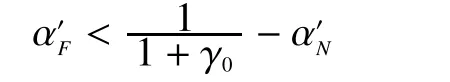
Serving mobile terminals at cell-edge could be very difficult due to the increased transmission power and cochannel interference to other devices.Furthermore, the rapid proliferation of smart devices lead to more scenarios of supporting multiple cell-edge users concurrently [1,2].However, serving multiple celledge users simultaneously with guaranteed data rate could be very challenging in 5G due to the significant amount of resources needed by such users.Therefore, new strategies with improved network efficiency and minimized interference are urgently needed to serve multiple cell-edge users in 5G concurrently.Relay and cooperative communications have been studied in improving the cost-effectiveness of serving cell-edge users.By reducing the communication distances of the S-R and R-D links, transmission power of source and relay nodes can be significantly reduced while maintaining low level of interference and high signal-to-noise ratio (SNR) at the destination.Meanwhile, as a promising 5G technology,NOMA can be used at the relay node to dramatically improve the spectral efficiency by supporting multiple edge users concurrently.It allows non-orthogonal utilization of the same time, spectral and spatial resources by multiple users simultaneously.With interference cancellation and power allocation [3,4],mutual impact due to the non-orthogonality among users can be controlled.Particularly,users with good channel conditions decode the messages for users with poor channel conditions first and then remove their impact by Successive Interference Cancellation (SIC) in order to decode messages for their own [5].As a result, the application of NOMA at relay nodes to enable concurrent multiple message receiving and transmitting for the relay is a promising solution to serving several cell-edge users simultaneously.
In this paper, we propose two NOMA assisted relaying systems for 5G based on the collaboration of the S-R NOMA link as macro-cell communication and R-D NOMA link as small-cell communication.In the CNAR system, the BS superimposes multiple messages intended for the relay and cell-edge users as a NOMA signal.The relay decodes its own message from the NOMA signal by SIC.The relay then combines messages for cell-edge users with adjusted power as another NOMA signal before send it to the destinations.To support multiple users, the S-R and R-D phases are linked by a dual-antenna relay operating in full-duplex mode for high throughput.Furthermore, the S-R and R-D phases are arranged in licensed and unlicensed bands, respectively, to avoid interference.To reduce the complexity of CNAR, a S-CNAR system is developed as an alternative of the proposed NOMA assisted relay.The reduced complexity is achieved since the relay only decodes its own message by considering other messages and the environmental noise as the equivalent noise.Then the relay amplifies the residual part of the source NOMA signal to cell-edge users without adjusting the message power levels.Nevertheless, the performance of proposed systems has to be characterized and power allocation should be specified to provide the data rate guarantee for multiple users.
Several recent studies have been done on the performance of NOMA assisted relaying systems.In [6], the capacity of a NOMA enabled decode- and-forward (DF) relaying system is evaluated and the corresponding suboptimal power allocation mechanism is proposed.The authors in [7] analyze the outage probability of the raised relay selection schemes for a NOMA system.Moreover, the outage probability and ergodic capacity expressions for NOMA downlink cooperative networks are derived in [8].Y.Liu et al.provides a cooperative SWIPT NOMA protocol and the close-form expressions for the associated outage probability [9].Nevertheless,these works focus on low-throughput half-duplex relaying model where the cell-edge user receive SNR is jointly determined by direct communications from the BS and the relay.
With the use of full-duplex in our NOMA assisted relaying systems, the system performance is evaluated in the following steps.Firstly, we define that the outage occurs if the achievable rate related to any message doesn’t reach their target rates.The system outage probability expression is then analyzed by considering the outage behavior of S-R and R-D phases separately.Next, we optimize power allocation ratios among different messages by minimizing the system outage probability to guarantee the single-user data rate.Following this, the ergodic sum capacity of proposed systems in high SNR regime is evaluated according to the optimized power allocation ratios.
The remainder of this paper is organized as follows.Section II describes the CNAR system design.Based on the analysis of system outage probability, an optimal power allocation mechanism is proposed by minimizing the outage probability.The ergodic sum capacity is then evaluated in this section.In Section III,the S-CNAR system is developed with similar method in the last section to evaluate outage probability, ergodic capacity and power allocation.Then numerical results are presented and analyzed in Section IV.Finally Section V concludes the paper.
II.COLLABORATIVE NOMA ASSISTED RELAYING SYSTEM
2.1 System design of CNAR
Our proposed CNAR communication system is illustrated in Fig.1.Suppose that a BS is serving three mobile terminals (MTs), among which MT1 is the closest to BS.Due to long distance from the BS to the cell-edge users MT2 and MT3, the BS cannot directly communicate with them with reasonable quality.Thus, we involve MT1 as a relay to connect BS and MT2, MT3.Under this circumstance,two phases are identified for the BS to serve these three MTs.
In this first phase, namely S-R phase, the BS superimposes three messages for MT1,MT2 and MT3 as a NOMA signal for transmission to MT1.MT1 receives this signal and decodes all three messages.In the second phase, namely the R-D phase, MT1 superimposes messages for MT2, MT3 with adjusted power as a new NOMA signal and to be transmitted to MT2 and MT3.MT2, MT3 receive the signal and acquire messages for their own.We suppose each MT is a dual-antenna device.To achieve high throughput, MT1 works in full-duplex mode.It receives the NOMA signal from the BS by one antenna and, at the same time, transmits another NOMA signal containing decoded messages in last time slot by the other antenna to cell-edge users.Furthermore, the S-R phase is operated as licensed band macro-cell communication, and the R-D phase is operated as unlicensed band small-cell communication to avoid the interference.All users share a common channel.We assume that each user has a half-duplex transceiver.Capture effect is not considered and the interference occurs when one user is transmitting and receiving simultaneously or receiving packets from different flows at the same time.Signal propagation delay is ignored, thus packets can be received by destinations immediately.Furthermore, we assume that users always have packets to transmit all the time.
Specifically, the BS superimposes three messages during the S-R phase as the NOMA signato be transmitted it to MT1.andare messages for MT1, MT2 and MT3, respectively.is the transmit power from one BS antenna to serve these three MTs.andare the power allocation ratios forandwhereConsequently, the received signal for MT1 is expressed as


Fig.1 Collaborative NOMA Assisted Relaying system model

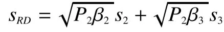

In each time slot, we are supposed to identify NOMA far user and near user for SIC to be most probably executed at near user [11].Supposing maximal ratio combining (MRC)is used at MT2, MT3, the equivalent channel gains for them areandrespectively.Therefore, whenMT2 is identified as near user with power ratio for near userand MT3 as far user with power ratio for far userotherwise, their statuses are switched with

In fact, MT1 is a DF relay to establish the connection between the S-R and R-D phases.Since the end-to-end data rate of DF relaying is determined by the weakest link [12], the achievable rate associated withandare

2.2 CNAR system performance analysis
In this section, we derive the system outage probability and propose the optimal power allocation scheme by minimizing e outage probability.Based on the proposed power allocation scheme, we present the analysis of the ergodic sum capacity.
2.2.1 Outage probability and power allocation
We define that during the proposed two-phase communication in our CNAR system, if the achievable rate associated with any message is lower than the target rate, the oage occurs.We set EventA= {All constraints in (1) are met}for the S-R communication, EventB= {All constraints in (2) are met} for the R-D communication.Thus, the system outage probability is expressed as


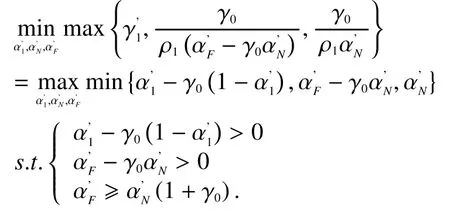
According to [13],tis introduced to denote the objective of Problem (7).In this way,Problem (7) is equivalent to

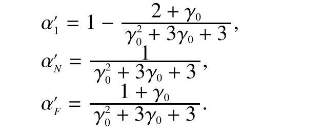
Since Problem (8) is convex, the solution is given by


For power allocation ratios in the R-D phase, it is very easy to exhaustively search possiblevalues withinto find the optimalformaximization.Thencan be calculated by
2.2.2 Ergodic capacity
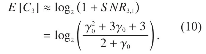
It is difficult to calculate the exact expressions of ergodic capacity in CN system.Hence, approximations of ergodic sum capacity highandregime are provided by analyzing the achievable rate for each message as follows.
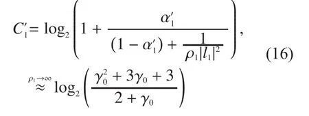
In the S-R phase transmission for, by applying

we get the achievable rate of BS-MT1 channel as

On the basis of (3), we calculateby discussing the result ofas follows.Forifis large.Forin high, if MT2 is far user, it holds thatleading toMT2 is near user condition onthe result ofis alsoHowever, if MT2 is near user withbecomesThe above cases are listed in Table I.
Define EventD= {MT2 is near user conditioned onWe prove in Appendix B that whenis givenlarge value,Therefore, EventDseldom happens, which indicates
Table I Discussion on in high .regime
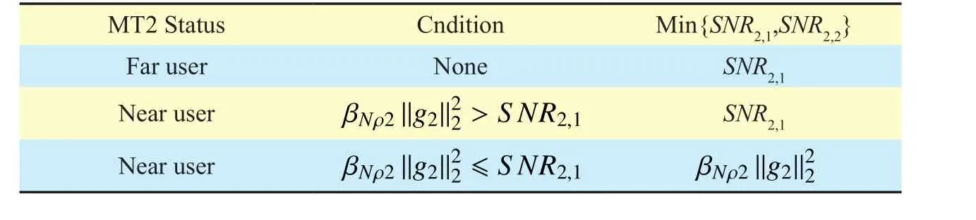
Table I Discussion on in high .regime

Fig.2 Simplified CNAR system model


III.SIMPLIFIED COLLABORATIVE NOMA ASSISTED RELAYING SYSTEM
In the abovementioned CNAR system, the process of decoding and forwarding at the relaying device is a little complex to operate since the relay should decode all three messages by SIC and superpose two messages into a new NOMA signal.In the transitional stage from 4G to 5G, the smart device still has relatively limited decoding and forwarding capability.Therefore, a simplified relaying mechanism with corresponding power allocation is proposed in this section as follows.The reduced complexity is achieved by fixed power allocation ratios, direct decoding and simplified forwarding schemes.
3.1 System design of S-CNAR
We propose a S-CNAR system as an alternative relaying strategy, illustrated in Fig.2,by modifying the relaying process in CNAR system.In other words, the basic settings in the CNAR system are still used in S-CNAR except the relaying process and related power allocation ratios.
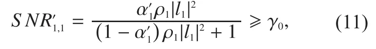
Here we elaborate the simplified relaying mechanism.During the S-R phase, BS superposesandas the NOMA signalto be transmitted to MT1 whereandare the power ratios forandrespectively.Upon receivingMT1 directly decodes the message for its own without applying SIC.Particularly, it treatsandas the equivalent noise to decode.To reach the target SNRthe following condition should be satisfied:


In a similar manner, we identify near user and far user in each time slot.We denote that the power allocation ratio for near user signal isand the one for far user signal is.If MT2 is identified as the near user, we obtainandotherwise, the relationship becomes
The achievable rate associated withandare

3.2 S-CNAR system performance analysis
In this subsection, we provide the system outage probability analysis and specify the related power ratios, on the basis of which the ergodic sum capacity is also analyzed.
3.2.1 Outage probability and power allocation
The same definition of outage probability in CNAR system is followed here.We also define EventK= {The constraint in (11) is met} for the S-R communication, EventM={All constraints in (12) are met} for the R-D communication.Therefore, the system outage probability is given by

Since it is difficult to derive the exactwe separately analyze the outage performance of EventMandKfor power ratio specification.


Similarly, it is reasonable to set lower channel gain threshold for far user than near user.Thus, we obtainwhich indicates

From the above analysis, we provide a sub-optimal power allocation scheme by considering satisfying the constraints from (13)(14)(15), which is equivalent to the following problem
By applying the same method to solve Problem (7), the results are given by
3.2.2 Ergodic capacity analysis
Here again, we provide the capacity analysis in high SNR regime as what is done for CNAR system.
In the S-R phase, the capacity for MT1 is approximated as:
In the R-D phase, the approximation of PSNR at far user can be expressed as:

The PSNR at near user is given by

If we assume MT2 is closer to the BS than MT3, some rough results ofandcan be obtained.It’s highly probable for MT3 to be the far user, sois a little higher thanSince MT2 is possible to be the near user,is only relatively high rather than infinite.

Fig.3 Outage probability as a function of target rate R0 when 15.5dB
IV.NUMERICAL RESULTS
We compare the performance of outage probability and ergodic capacity obtained by CNAR,S-CNAR, conventional orthogonal multiple access (OMA) and the OMA-based relaying systems.In all systems, for the illustration purposes, we assume that the BS and all MTs are on a straight line.Suppose BS-MT1 distanceMT1-MT2 distanceand MT1-MT3 distance.Assume thatwhere the path loss exponentis 3.9 and the reference distanceis 100m.In this way,andget.
Note that there are special assumptions for the OMA-based systems.In conventional OMA system, the BS transmitsandby one third time resource, respectively, in both the licensed and unlicensed frequency band.Particularly, in an individual manner, the corresponding outage probability is computed by taking the average of the three MTs’ individual outage probabilities since each MT communicates with the BS without cooperation and interference.This is denoted as Conventional OMA (I) in Fig.3.On the contrary, in a systematic consideration, the outage probability follows the definition in CNAR system.It is expressed as Conventional OMA (S) in Fig.3.In the OMA-based relaying system, it is supposed thatandare sent by the BS in one third time resource via the S-R link,respectively;andare transmitted by MT1 in half time resource via the R-D link, respectively.
Fig.3 presents the outage probability as a function of target ratewhenOne can observe that the theoretical analysis is verified by the simulation results.For lower-valuethe outage probability by conventional OMA is the lowest among these transmission strategies.Nevertheless, when R0 grows larger as practical user data rate requirements for 5G,CNAR obtains the lowest outage probability and S-CNAR holds the second lowest one.
In Fig.4, we plot outage probability with regard to whenDue to very poor outage performance from systematic consideration for conventional OMA, in this figure, we only show conventional OMA’s outage probability in the individual manner.Here again,with theoretical outage results verified, the outage probability by CNAR system stays a little lower than S-CNAR and a lot lower than OMA transmission strategies.Furthermore,when grows, the outage probability by CNAR doesn’t decrease remarkably.The reason is based on Eq.(5), if large causesis lower-bounded by
Fig.5 demonstrates the results of ergodic capacity if the target ratedB.The figure shows that the approximations of the capacity in CNAR system well match the simulation results.And our power allocation scheme makes the ergodic capacity of each CNAR user above the target rate.Additionally, CNAR has sum capacity gain over the OMA-based one because NOMA enables each user to exploit all time resource while OMA limits the time resource that each user can use.
In subfigure (a), it shows that the approximations of the capacity in CNAR system can match the simulation results.The CNAR mechanism obtains the highest sum capacity and S-CNAR achieves lower capacity.The reason is shown in subfigure (b).is slightly larger thanbecause the PSNR expression at MT2 in S-CNAR contains more noise components than that of MT1 in CNAR.The values of capacity for other single users in the second subfigure are close to the approximated results in (9)(10)(16)(17).We can also observe that our power allocation schemes enable each single-user achievable rate in CNAR and S-CNAR to be over the target rate.

Fig.4 Outage probability as a function of target rate when R0=2.1

Fig.5 Ergodic capacity as a function of MT1 transmit SNRwhen R0=2.1 and
V.CONCLUSIONS
This paper develops a CNAR system and a low complex S-CNAR system to serve multiple cell-edge users concurrently with guaranteed data rate.To characterize the performance for both systems, we analyze the outage probability by regarding the outage behaviors in the S-R and R-D links separately.Then we propose the optimal power allocation scheme to guarantee the data rate by minimization of the outage probability.Furthermore, we provide the ergodic sum capacity approximation in high SNR region.Numerical results validate the theoretical analysis.It is also demonstrated that the proposed CNAR achieves the best performance among possible transmission strategies and S-CNAR obtains similar performance with reduced relaying complexity.
Appendix A
With the probability density function (PDF)for Rayleigh channel, it is easy to get the following PDF ofand

Appendix B

[1] ZHENG, Kan, et al.Multihop cellular networks toward LTE-advanced [J].IEEE Vehicular Technology Magazine, 2009, 4(3): 40-47.
[2] FANG, Fang, et al.Energy-Efficient Resource Allocation for Downlink Non-Orthogonal Multiple Access Network [J], IEEE Transactions on Communications, 2016, 64(3), 3722-3732.
[3] LI, Anxin, et al.Non-orthogonal multiple access(NOMA) for future downlink radio access of 5G[J].China Communications, 2015, 12.Supplement: 28-37.
[4] DAI, Linglong, et al.Non-orthogonal multiple access for 5G: solutions, challenges, opportunities, and future research trends [J].IEEE Communications Magazine, 2015, 53(9): 74-81.
[5] LIU, Xin; WANG, Xianbin.Outage probability and capacity analysis of the Collaborative NOMA Assisted Relaying system in 5G [C].In:2016 IEEE/CIC International Conference on Communications in China (ICCC).IEEE, 2016.p.1-5.
[6] KIM, Jung-Bin; LEE, In-Ho.Capacity analysis of cooperative relaying systems using non-orthogonal multiple access [J].IEEE Communications Letters, 2015, 19(11): 1949-1952.
[7] DING, Zhiguo; DAI, Huaiyu; POOR, H.Vincent.Relay Selection for Cooper ative NOMA [J].2016.
[8] MEN, Jinjin; GE, Jianhua.Performance analysis of non-orthogonal multiple access in downlink cooperative network [J].IET Communications,2015, 9(18): 2267-2273.
[9] LIU, Yuanwei, et al.Cooperative non-orthogonal multiple access with simultaneous wireless information and power transfer [J].IEEE Journal on Selected Areas in Communications, 2016,34(4): 938-953.
[10] LIU, Fei; MÄHÖNEN, Petri; PETROVA, Marina.Proportional fairness-based user pairing and power allocation for non-orthogonal multiple access [C].In: Personal, Indoor, and Mobile Radio Communications (PIMRC), 2015 IEEE 26th Annual International Symposium on.IEEE, 2015.p.1127-1131.
[11] CHOI, Jinho.Minimum power multicast beamforming with superposition coding for multiresolution broadcast and application to NOMA systems [J].IEEE Transactions on Communications, 2015, 63(3): 791-800.
[12] BHATNAGAR, Manav R.On the capacity of decode-and-forward relaying over rician fading channels [J].IEEE Communications Letters,2013, 17(6): 1100-1103.
[13] BOYD, Stephen; VANDENBERGHE, Lieven.Convex optimization [M].Cambridge university press, 2004.
[14] JEFFREY, Alan; ZWILLINGER, Daniel (ed.).Table of integrals, series, and products [M].Academic Press, 2007.
杂志排行

China Communications的其它文章
- Offline Urdu Nastaleeq Optical Character Recognition Based on Stacked Denoising Autoencoder
- Toward a Scalable SDN Control Mechanism via Switch Migration
- Reputation-Based Cooperative Spectrum Sensing Algorithm for Mobile Cognitive Radio Networks
- Identifying the Unknown Tags in a Large RFID System
- Dynamic Weapon Target Assignment Based on Intuitionistic Fuzzy Entropy of Discrete Particle Swarm
- A Non-Cooperative Differential Game-Based Security Model in Fog Computing