ASSESSMENT OF AN ELECTRO MECHANICAL DIFFERENTIAL GEAR PROVIDING VARIABLE SPEED TO INDUSTRIAL APPLICATIONS
2016-12-20MaximilianHehenberger
ASSESSMENT OF AN ELECTRO MECHANICAL DIFFERENTIAL GEAR PROVIDING VARIABLE SPEED TO INDUSTRIAL APPLICATIONS
■
当前,标准工业应用对于整体传动系统效率的要求日益提高,如压缩机、鼓风机、风扇及水泵。现有的系统如VFD或液压变速控制系统不能满足能源成本的需求。几年前一个创新性的变速系统EMDS(机电差速系统)出现在市场上,在总效率和初始成本上显示出巨大的潜力。该系统由一个主驱动(直接连接电网)、一个包含行星齿轮级的齿轮箱和一个伺服变频控制驱动组成。伺服驱动(最大为系统总功率的20%)通过主驱动的恒定速度来控制齿轮箱输出速度。此外这一设置使得电力元件最少化同时在整个传动当中占用空间小。研究表明,该系统可应用于最高至15MW和15 000r/ min速度的变速应用上。长期运行将证明,该方案是否能安全满足工业的高标准和需求。作者对比了EMDS和其他变速系统的技术优势,并分析了EMDS的技术原理并包括详细的效率对比。此外还给出了实际应用证明案例。
electro-mechanical differential gear;drive train;motor;variable speed;low voltage frequency converter
Abbreviations
ASM asynchronousmachine
DC directcurrent
EMDG electro-mechanicaldifferentialgear
HDC hydro-dynamic coupling
IGBT insulated-gatebipolar transistor
LCC life cycle costs
LV low voltage
MSD motorsynchronization device
PUD pull-up device
VFD variable frequency drive
Abstract:Nowadays there is an increasing pressureon industry to increase theefficiency of thewholedrive train forstandard industrial applications like compressors,blowers,fans and pumps.Onemajor key to ensure thishigh energy savings is the regulation of speed and power according to the actual demand of the driven machine.Common systems like the VFD(variable frequency converter)or hydraulic variable speed control systems meet the requirements unsatisfactory w ith respect to energy costs.Since a couple of yearsanew innovativevariablespeed system the EMDS(electro-mechanical differential system)is on the market show ing high potential in terms of total efficiency and initial costs.This system consists of amain drive(directly connected to the grid),a gearbox incl.a planetary gear stage and a frequency controlled servo drive.The servo drive(max.20%of the total system power) controls the outputspeed of the gearbox by a constant speed of the main drive. Furthermore,this set-up leads to aminimum amountof electrical components and a small overall footprint of the complete drive train. Investigations have demonstrated that this system is applicable for variable speed applications up to 15MW power and 15.000rpm speed.Long-term operation w ill prove,if this approach does satisfy the industry’s high standards and needs.The Author compared the technical advantages between EMDS and other variable speed systems and analyzed the technical principle
Introduction
Today industry worldw ide is subject to major changes as a result of global warm ing,fast changing commercial conditions,and air pollution.The policy is to ensure the continued availability of natural resources and to preventa collapse of the environmentalsystem.
In Germany,for example,industry uses 30%of all electricity in the country. Of that figure,70%is consumed by electrically driven machines.The energy costs of these machines account for at least 80%of the total life cycle costs[1].In Strategy Europe 2030,the European Union(EU)has defined the goals for energy management until 2030.The agreement specifies a reduction in CO2em issions of 40%and an increase in both renewable energy and energy efficiency of 27%[2].
Furthermore,in 2011 the EU issued regulations stating m inimum efficiency requirements for electricmotors.At the beginning of 2015 a directive came into force requiring speed regulation in IE 3 motors between 7.5 and 375 kW,as reflected in the EN 50598 series standard[1,3].Thus,there is increasing pressure on industry to increase the efficiency of the whole drive train.There is also a high demand for both cost effective and efficient drive train systems and the policy to develop extensive,forward-looking legislation.
State of Drive Train Concepts
There are a couple of ways to provide speed from an electric machine to a driven machine,as shown in Figure 1.The first and the easiest one is the direct drive,Figure 1 a.The drivenmachine is connected directly to the main drive(E-motor), which is directly connected to the grid-a variation of speed is not possible.To adjust the exact flow rate valves,dampers or bypasses are used. A lthough the apparent costs are low,the LCC are very high due to the main drive's continuously high energy consumption.
In the oil industry turbines utilizing by-products from refinery processes are often used to drive machines.The flow is adjusted by fuel or steam controls or adjustable turbine blades changing the speed of the turbine,shown in Figure 1c.However,as efficiency increases w ith the size of the turbines,the investment may not be econom ically viable for smallapplications.
Currently the most common systems providing variable speed are the variable frequency drive(VFD)and the hydro-dynamic coupling(HDC)like the Vorecon from Voith,for example,shown in Figure 1d and b.In this paper a basic know ledge of these technologies is assumed; for further information please refer to the appropriate technical literature[4-5].Applications which provide variable speed achieve a much better performance in terms of energy efficiency, resulting in lower LCC.However,while the VFD system appears to be cost effective for low power applications,the costs increase significantly for medium voltage VFD at a multi MW level. Furthermore,air conditioned rooms have to be provided to sustain the operation and furthermore, maintenance rates are empirically high,due to the sensitivity of IGBT modules.W ith no power electronics along the main power path the HDC system has a statistically higher endurance.But the disadvantages of the HDC are the large footprint(including a complex lubrication system) and the low efficiency in case of speed deviation from rated speed.
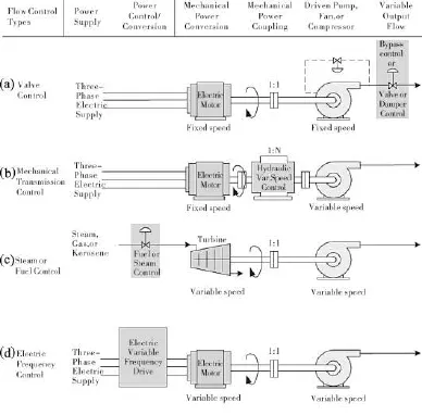
Figure 1 Schamatic representation of common drive train systems[9]
An alternative approach is the EMDG.The next section briefly explains the system architectureand functionality.
Electro-Mechanical Differential Gear:Architecture and Functionality
Figure 2 shows the principle of an EMDG system(7)consisting of the differential stage(2) including the pre-stage gear(3),differential drive (servo)(5),and a small low-voltage frequency converter(6).Themain drive(1),preferably a 4 to 6-pole medium-voltage asynchronous machine (ASM),drives the ring gear of the differential stage(2)w ith constant speed.The differential stage's planet carrier is connected to the driven machine(4)through an optionalpre-stagegear(3), transm itting variable speed.This variable speed is provided by the differential drive(5),which is connected to the differential stage's sun gear.The differential drive adjusts the variable speed deviating from rated speed.
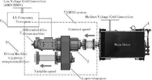
Figure 2 EMD system architecture[7]
The differential drive is a low-voltage three-phase ASM,which is connected through the low voltage frequency converter(6)to a low-voltage grid.Figure 3 shows the differential stage'spower paths in detail.
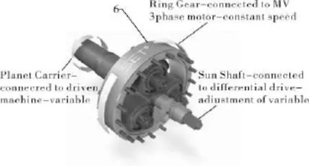
Figure 3 Differentialstage[7]
The EMDG can be manufactured as a separate assembly and therefore installed and maintained independently of the main drive as a standalone unit.The system is self-contained and performs all control and feedback tasks automatically.The interface for controlling the system from outside can bemaintained through a large variety of existing types of interfaces.In general,the system components do comply w ith standard components,w idely used in the industry, which increases its reliability significantly.
Technical Background
The relation between the speeds in the differential stage of the EMDG is shown in the follow ing equation:
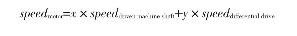
Where the motor speed is constant,and factors x and y can be derived from the transm ission ratios of the pre-stage gear and the differential stage.The torque at the driven machine's shaft is determ ined by the delivery head and flow rate required.The ratio between the torque at the driven machine shaft and that at the differential drive is constant,enabling the torque in the drive train to be controlled by the differential drive.The torque equation for the differentialdrive:
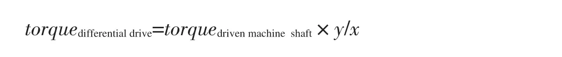
Where the factor y/x is a measure of the necessary design torque for the differentialdrive.
The differential drive's power rating is essentially proportional to the product of the percentage the driven machine speed deviates from its“basic speed”time’s shaft power.As a result,a w ide speed range basically requires the differential drive to be dimensioned accordingly.
Figure 4 shows an example of the power ratios of a differential stage for a driven machine. To work highly efficiently the differential drive utilizes both speed directions and operates as a generator and amotor depending on the set speed for the driven machine.Thismeans that power is supplied to the differential drive in the motor range and w ithdrawn from the differential drive in the generator range to be restored in the grid.The sum of motor power and differential drive power is equal to the total power delivered to the driven machine’s shaft.
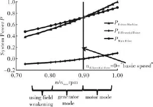
Figure 4 Speed and power ratios fora differentialstage[7]
By using an(integrated)pre-stage gear,any speed required can be achieved for the driven machine and thus the use of multi-pole drive motors can beavoided for stepping down speed.
Efficiency Com parison
Based on the fact that the losses from the differential stage are insignificantly low,the efficiency lim itations of the ASM(main drive) are decisive.In comparison the VFD system shows much lower efficiency,due to the losses from the frequency converter and auxiliary devices like filters,etc.At maximum speed the HDC shows comparable performance w ith the VFD system,but when operating speed deviates from the design point,the efficiency losses increase significantly.
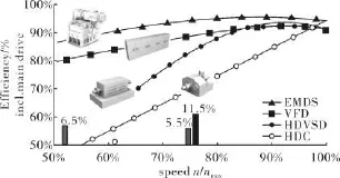
Figure 5 Totalefficiency comparison[5,9]

Figure 6 Total efficiency comparison by components[5,8,9]
Figure 6 shows in detail the efficiency of the individual components of various drive train concepts at maximum power.It is worth tomention,that only a maximal of approximately 10%of the power flows through the differential drives's power path in this case,leading to minimum losses of the whole system for the EMDG.
Life Cycle Costs
Figure 8 shows an example of the resultant LCC w ith respect to the common variable speed drive systems.The example compares 3 MW variable drive systems(EMDG,VFD,HDC) w ith the LCC of a fixed speed drive.The basis for this assessment is the efficiency comparison of the drive systems(Figure 6)and an assumed speed distribution for a compressor,as shown in Figure 7.

Figure7 Assumed speed and powerdistribution fora compressor peryear
Taking a 3MW VFD system as an example, the additional energy losses result in total costs of€50 000 per year-taking into account typical speed and power distribution,an electricity rate of€60/MW,and 8 500 operating hours per year.
W ith a net discount rate of 3%per year.this adds up to a total net present value(NPV)of€1 100 000 overa life cycle of 30 years.
Comparing the calculation of all drive systems(Figure 9),it becomes obvious that the investment costs of a fixed speed drive are the lowest ones.However,by taking the energy losses into account,the fixed speed system shows the highest LCC.Consequently,both the investment costs and the energy losses are reduced to a m inimum by using an EMDG system.The typical return on investment(ROI) compared to a fixed speed system is between one and two years only.
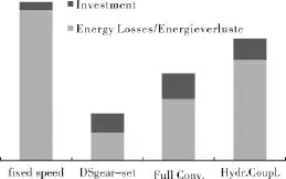
Figure 8 Comparison of life cycle costs
EMDG for a 4.1 MW boiler feed pum p at PCK site in Germany
The EMDG system points the way ahead for the entire industry sector.Sulzer Pumpen (Deutschland)GmbH awarded SET GmbH a contract to install its EMDG system at the PCK refinery in Schwedt(Germany).The EMDG w ill replace the existing direct drive system in order to meet future challenges in terms of sustainability and life cycle costs(LCC).The EMDG emerged as the best technology ahead of the competition in view of its speed variability range,efficiency,and robustness.
The installed system has to provide a rated power of 4 100kW for a boiler feedwater pump,which is essential for the refinery processesat the site.
In this flagship project the operating companies expect the EMDG to ensure high cost savings,maximum reliability and efficiency.Conditions
1)4.3MW ELINmotor-main drive
2)Max.torque 13.2 kNm atoutputshaft
3)Speed rangeoutputshaft2460~2980r/m in
4)Power rangeoutputshaft2.3~4.1MW
5)Soft-Star capability
System Specifications
1)System design according to customer's requirementsand building codesatsite.
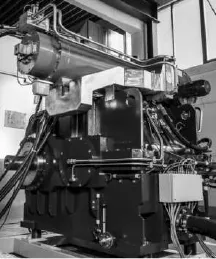
Figure 9 4.1MW EMDG
2)Development and analytical calculation (FEM,MBS,etc.)of gear box.
3)Selection and specification of the sub-assembliesas:
differentialdrive300kW
low voltage frequency converter300kW
lubrication unit
and controlsystem(DSControl)
Assembling
Testing at testbench
Commissioning atPCK site

Figure10 Set-up configuration atPCK refinery in Schwedt,Germany[10]
Conclusion
The industry demandspowerfulsystems in the future,and at the same time these systems should becomemore efficient.Common systems like the VFD or theHDC do notmeet the requirementsw ith respect to LCC.The EMDG isa drive train concept which showshigh potential forvariablespeed drives in industrial applications.The directly grid connectedmain drive and the smallelectronic parts forspeed and torque controlenableboth investment costs and losses to be reduced to am inimum.This results in a highly efficient variable speed drive system.Them inimum effort for power electronics for controlling the drive,the simple design of the differential drive and a well-known gearbox concept guarantee the highest possible reliability. Industry requirements concerning startup,grid losses etc.can be fulfilled by modifying the EMDG'sdesign.Long-term operationw illprove,if this approach does satisfy the industry's high demands.
Reference
[1]SiemensAg.Energieeffizienz in Bewegung[R].Dispostelle 21511,2014.
[2]Bundestag D..Position der Bundesregierung zu den Vorschlägen der Europäischen Komm ission zu den europäischen Klima-und Energiezielen 2030[R]. Berlin:H.Heenemann GmbH,2014.
[3]Normung D.I.f..Eco design for power drive systems,motor starters,power electronics&their driven applications-Part2: Energy efficiency indicators for power drive systems and motor starters[M].Berlin:Beuth Verlag GmbH,2013.
[4]Jenk J.Voltage Frequency Converter Basics in Simplified Design of Voltage:Frequency Converters[C].Woburn: Butterworth-Heinemann,1997.
[5]Voith Turbo.Hydrodynam ic Couplings,Principles Features Benefits.Voith Turbo GmbH&Co.KG,[19.02.2015].http:// voith.com/en/1614_e_cr394_en_hydrodynamic-fluidcouplings_principles-features-benefits.pdf.
[6]Senty S.Motor Control[M].New York:Delma,2013.
[7]VDMA.Highly efficientspeed regulation for centrifugal pumps.Klaus Löffler,Dirk Küllmey[e-magazine].http:// www.3d-zeitschrift.de/p/6g7IlykacpMSx/Pumps_and_ Compressors for_the_World_Market_2016.htm l?page=1.
[8]ElinMotorenGmbH.Lastprüfung:DSgear-set,10.08.2015, Weiz.
[9]TMEIC Corporation.Slection variable Speed Drives for Flow Control.http://www.tmeic.com/Repository/BrochuresSelecting_ VSDs_for_Flow_Control_Brochure-2011_low-res_ 1314113714.pdf.
[10]Sulzer.VölligneuartigeDrehzahlregulierung fürKesselspese-Pumpen[J].Delta P,2016(1):41.
Maxim ilian Hehenberger/SETSustainable Energy TechnologiesGmbH
机电差速齿轮;驱动机构;电机;变速;低压变频器of EMDS including a detailed efficiency comparison.Additionally,a case of practical application isdemonstrated.
TH133.3;TK05
A
1006-8155(2016)03-0078-06
10.16492/j.fjjs.2016.03.0027
Received date:2015-03-19 Klagenfurt Austria 9020