Methodology for predicting optical system performance when subjected to static stresses
2016-12-12ALLAHAMRadwanMOUSSELLYMhdFawazNAIMMamoun
AL-LAHAM Radwan, MOUSSELLY Mhd.Fawaz, NAIM Mamoun
(Higher Institute for Applied Sciences and Technology,Damascus,Syria)*Corresponding author, E-mail:eng.rad.laham@gmail.com
Methodology for predicting optical system performance when subjected to static stresses
AL-LAHAM Radwan*, MOUSSELLY Mhd.Fawaz, NAIM Mamoun
(HigherInstituteforAppliedSciencesandTechnology,Damascus,Syria)*Correspondingauthor,E-mail:eng.rad.laham@gmail.com
High performance optical systems are characterized by high sensitivity to assembly procedure of the system and to any sensible change in environmental conditions. This sensitivity issue is handled in this paper through a methodology allowing a computational prediction of optical performance when the opto-mechanical system is subject to some external factors. This paper explains the methodology through an example of an optical objective of excellent performance undergoing static mechanical stresses which degrade the performance expressed by an MTF diagram. Then the objective is manufactured, assembled, and an optical interferometer is used to test the objective when stress is retained; and the experimental results of degraded MTF are compared to the analytical MTF. The excellent matching between the two sets of results confirms the validity of the proposed methodology.
predicting optical performance;assembly of optical system;tensile torque;MTF;objective;Ansys;Matlab
1 Introduction
Optical systems are essential components in astronomy, scientific devices, medical instruments, and military equipments. Therefore, there has been a considerable research effort dedicated to designing and optimizing optical systems, and to evaluating their performances. This evaluation has been traditionally based on optical criteria developed during the twentieth century such as the PSF or MTF resulting from the numerical analysis of optical designs[1]. But this evaluation remains practically incomplete unless it includes an analytical study on the effect of static and dynamic mechanical stress resulting from the effect of fixing optical elements within their mountings(i.e. assembly of optical systems), the expansion of the optical elements in an environment with variable temperature, or the exposure to shockwaves or vibration[3].
In all cases, the various types of stresses adversely affect the quality of the image formed by the optical system, and the system may completely fail to accomplish its function if these stresses exceed certain limits related to opto-mechanical design. For example, tension of an optical element with a retainer leads to surface deformation and generates stresses within this element, and these stresses depend on the shape of the contact contour between the element and the metallic mounting(sharp corner-torodial contact-tangential contact-circular contact-…[4]). If these stresses exceed 345 MPa as a compression stresses, the optical element will breakdown[1,4-5].
The available scientific articles do not offer enough information about how the optical system performances could be analytically evaluated under various environmental conditions(stresses-pressure-temperature-…). The only significant work is presented under the form of the program “SIGFIT”. This software converts finite elements analysis(FEA) thermal and structural results obtained using the program ANSYS(or NASTRAN), into any of the well-known optical analysis programs such CODE V, ZEMAX, or OSLO[6].
The accessible publications in this field include the research presented by Victor Genberg, Gregory Michels, and Keith Doyle who studied the effect of both temperature and stresses on the refractive index of glass materials using the finite elements method and its effect on the optical path difference[6-8]. They also investigated the behavior of adaptive optics and provided the obtained results under a form appropriate for optical design programs[9]. Furthermore, their research included a comprehensive study on the resulted birefringence[10-11]. However, the validity of the mentioned results depends on the correctness of the software SIGFIT which has not been thoroughly tested by independent institutions.
Available publications also include the work of Martin Booth and his colleagues who developed two methods to characterize membrane deformable mirrors that were used in adaptive optical systems. One of these two methods utilizes a simple interferometer, and the deformable mirror is inserted in one arms of the interferometer and then they analyzed the fringes resulted from the mirror deformation[12].
In this paper, we present a detailed study on the effect of static stresses on optical elements, specifically in the case of optical systems of very high performances, such as projective microlithography devices and space telescopes[4]. In such systems the stresses effects are not negligible compared to optical aberrations, and they may cause the optical system to fall short of fulfilling its intended functions. Therefore, a high performance objective lens has been designed for the sake of this study, and the methodology shown in Fig.1 was adopted in order to investigate the effective optical performance of this objective under static stresses. Practical confirmation of this methodology is illustrated in Fig.2 where an interferometer with double-pass auto-collimation was used.

Fig.1 General scheme for predicting optical performance through the static structural analysis[3]

Fig.2 Verification of optical system performance using a double-pass auto-collimation interferometer
2 Optical design of the objective
The current work included the application of the proposed methodology to predict the optical performance of a variety of objectives and eyepieces of telescopes that operate in the visible, and typically have a resolution less than 100 lp/mm. The results assert that the mechanical tension has no effect on the optical performance because the optical aberrations are much higher than the degradation caused by the tensile even when increased up to the break point of the glass material of the optical element. Therefore, it is necessary to apply the suggested methodology to an optical system of high performance so that a practical confirmation could be clearly observed and quantified.
The well-known optical design program ZEMAX was used to design an objective with a very high resolution reaching 625 lp/mm atλ=628.3 nm and for an on-axis object point. Tab.1 shows the parameters of the designed objective, and Fig.3 displays its diffraction limit performance with a cutoff frequency 625 lp/mm.

Fig.3 Optical performance of the designed objective
Additionally, the tolerances analysis within ZEMAX confirms that this objective has low sensitivity to inevitable tilts and decenter errors of its lenses. Therefore, when applying mechanical tension to the optical elements of the objective, any decrease of optical performance will be originated only from the tension.
3 Applying the prediction methodology of optical performance
The modeling of stresses and tensions is generally realized by “finite elements method” with any from a set of approaches relating all parameters of the case study:geometric form, downloading method, retaining method, the behavior of materials,etc. The modeling is commonly done within one of the specialized programs such as ANSYS or NASTRAN.
This modeling by ANSYS was applied to the opto-mechanical objective formerly designed, with suitable conditions and restrictions(retaining force-temperature-…) governing the system. Next, the problem was resolved for the first lens of the objective and the deformations were presented. The following parameters and criteria were applied in the modeling:
(a)Because the lens has circular symmetry in its mounting, the 3D shape had been reduced to only one quarter with restrictions on all nodes plans (a,b) in horizontal direction(levels XY-ZY)(Fig.4).
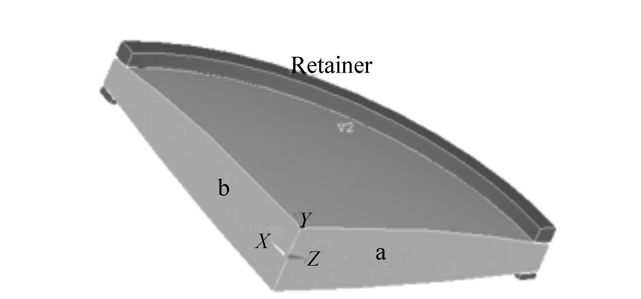
Fig.4 One quarter of the lens
(b)The used element for 3D structure modeling is Solid186 which consists of 20 nodes, and every node has three degrees of freedom.
(c)The behavior of glass is “linear elastic” within the “safe use” range, and Tab.2 presents the characteristic values of glass material of the current element. As for the behavior of the mounting material(aluminum alloy), it is nonlinear elasto-palstic, and its values shown in Tab.2 have been based on the stress-strain curve obtained from the static tension experiment carried out using a standard sample made from the alloy(Fig.5).
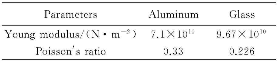
Tab.2 Characteristics of the materials used in the modeling

Fig.5 Stress-strain curve for aluminum material
(d)With respect to the modeling of contact surfaces between the optical element and both of the mounting and retainer metal, the modeling has been represented by a “contact model” available in Ansys. The used element(Targe169-Conta172) consists of three nodes in addition to the coefficients of friction associated with them. The values of these coefficients of friction between glass and aluminum are 0.6 as it is given in Ref.[15].
(e)The forces generated by the retainer on the optical element have been represented as “compressed transitions” along the vertical axis(the optical axis), and this is equivalent to applying a torque of 3 to 6 N·m.
(f)The number of elements is 15 328, and the number of nodes is 251 221 nodes.
Once the problem has been resolved, and the resulting deformation on surfaces nodes has been calculated(Fig.6), the translations(xi+Δxi,yi+Δyi,zi+Δzi) are stored in an Excel file.

Fig.6 Original surface deformation as a result of applied tension
Taking in calculations that the diameter of retainer(Torsion couple) is 60 mm, it is possible to numerically represent-Tab.3-the torque as a function of displacements of retainer.

Tab.3 Tensile torques values as a function of retainer displacement
Fig.7 illustrates the values generated within the
optical element due to a torque of 5 N·m along the optical axis(y-axis in the current example). Note that the maximum of compression stress 36.3 MPa is much lower than the stress of 345 MPa provoking a glass failure.

Fig.7 Generated stresses due to a torque of 5 N m along y-axis
After obtaining and storing the displacements of all nodes, they were mathematically processed within the the software MATLAB so they could define a new surface according to the following equation (1)[14]:
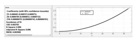
Fig.8 Expansion of deformed surface as a function of Zernike polynomials
the spherical surface;c=1/Ris the curvature at the summit; and (Z1,Z9,Z16) are Zernike polynomial coefficients. Since the tension has circularly symmetric effect, and then the meaningful terms are those related to spherical aberrations, in addition to a piston term representing a constant phase. Fig.8 shows the perfect matching between the deformed surface and the surface defined to be the previous equation with suitable coefficients. These results were obtained for a 3 N·m torque applied to the first surface within a confidence bounds of 95%.
Tab.4 shows Zernike polynomial coefficients at each surface of the lens for a set of tensile torques.
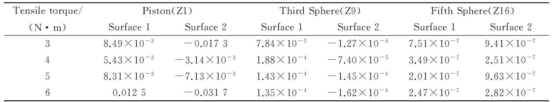
Tab.4 Zernike coefficients for a set of tensile torques
The next step involves inputting Zernike polynomial of the deformed surface into ZEMAX. These coefficients-Tab.4-were used to define a surface of the type “Zernike fringe sag surfaces”. Fig.9 shows the objective MTF under the influence of a set tensile torques.

Fig.9 Using Zemax to output MTF as a function of tensile torque
4 The practical investigation of the mechanical tension effect
The practical part involved the use of the following:
(1)Torque tool:This tool(Fig.10) is used to fasten the retainer by a certain torque whose value is in the range of 3-11 N·m. This tool was calibrated to an accuracy of 0.05 N·m.
(2)Adapter of steel:it is an intermediate piece(Fig.10) between the torque tool and the retainer of the optical element.
(3)Fizeau-Interferometer with an accuracy ofλ/50.

Fig.10 Torque tool and adapter of steel used in experiments
Firstly, all the optical and mechanical elements of the objective have been manufactured according the optical design previously presented in this paper. Then, all the elements were assembled without applying any mechanical tension on the first lens which has been selected to be subjected to the variable mechanical tension. The optical system is fixed on a movable stage with two degrees of freedom(horizontal and vertical) and facing an interferometer according to the adopted methodology.
The stage is adjusted in both directions to minimize various optical aberrations, as seen in Fig.11(a). Good adjustment leads to straight fringes, as seen in Fig.11(b), and that affirms the excellent quality of the objective whose P-V fringes error is ΔN=0.08λ.

Fig.11 (a)Measuring setup using an interferometer; (b)resulted fringes when no tension was applied to the optical element
In the next phase, the tension was gradually increased using the steel adapter and the torque tool,seen in Fig.12. The tension was varied within the range from 3 N·m to only 6 N·m because the deformation became very large and thus immeasurable by the interferometer. Fig.13 presents diagrams of fringes errors for several values of the applied tensile torque to the optical element.

Fig.12 Applying a tension on the optical element
All diagrams of Fig.13 comprise some astigmatism, and it is directly measurable by the interferometer. The origin of this aberration is the tolerated tilt between the lens surfaces during manufacture. This tilt was within the allowed tolerance, and the third order spherical aberrations was always the dominant aberration.

Fig.13 Diagrams of fringes errors of the optical system under test for several values of tensile torque

6N·m5N·m4N·m3N·mSpatialfrequencyMTF(computation)MTF(experiment)MTF(computation)MTF(experiment)MTF(computation)MTF(experiment)MTF(computation)MTF(experiment)01.0001.0001.0001.0001.0001.0001.0001.00062.50.7390.7910.6570.7170.6230.6580.5950.6141250.5100.5200.4090.4080.3550.4100.3120.278187.50.3640.3100.2760.2510.2250.2090.1860.1302500.3040.2680.2250.1920.1840.1600.1540.081312.50.2750.2510.2260.1890.1990.1400.1760.1153750.2310.2390.2100.1840.1970.1650.1870.179437.50.1360.1530.1170.1350.1060.0910.0990.1255000.0570.0710.0390.0660.0300.0540.0220.037562.50.0060.0150.0170.0170.0410.0220.0120.0176250.0000.0000.0000.0000.0000.0020.0000.002
Tab.5 shows the MTF values for the previous tensile torques, and Fig.14 shows the MTF diagram in two cases(computation-experiment) for the previous tensile torques and with deviation(2σ), since the tangential and sagittal MTF(for computational and experimental) are very close so the MTF has no significant astigmatism aberration.
The result gives the excellent match between the analytical and measured MTF for several values of tensile torques. This match validates the reliability of the methodology presented in this paper. More significantly, it confirms the possibility of a computational prediction of the functional performance of this kind of optical systems undergoing static mechanical stresses before actually manufacturing any element of the opto-mechanical system.
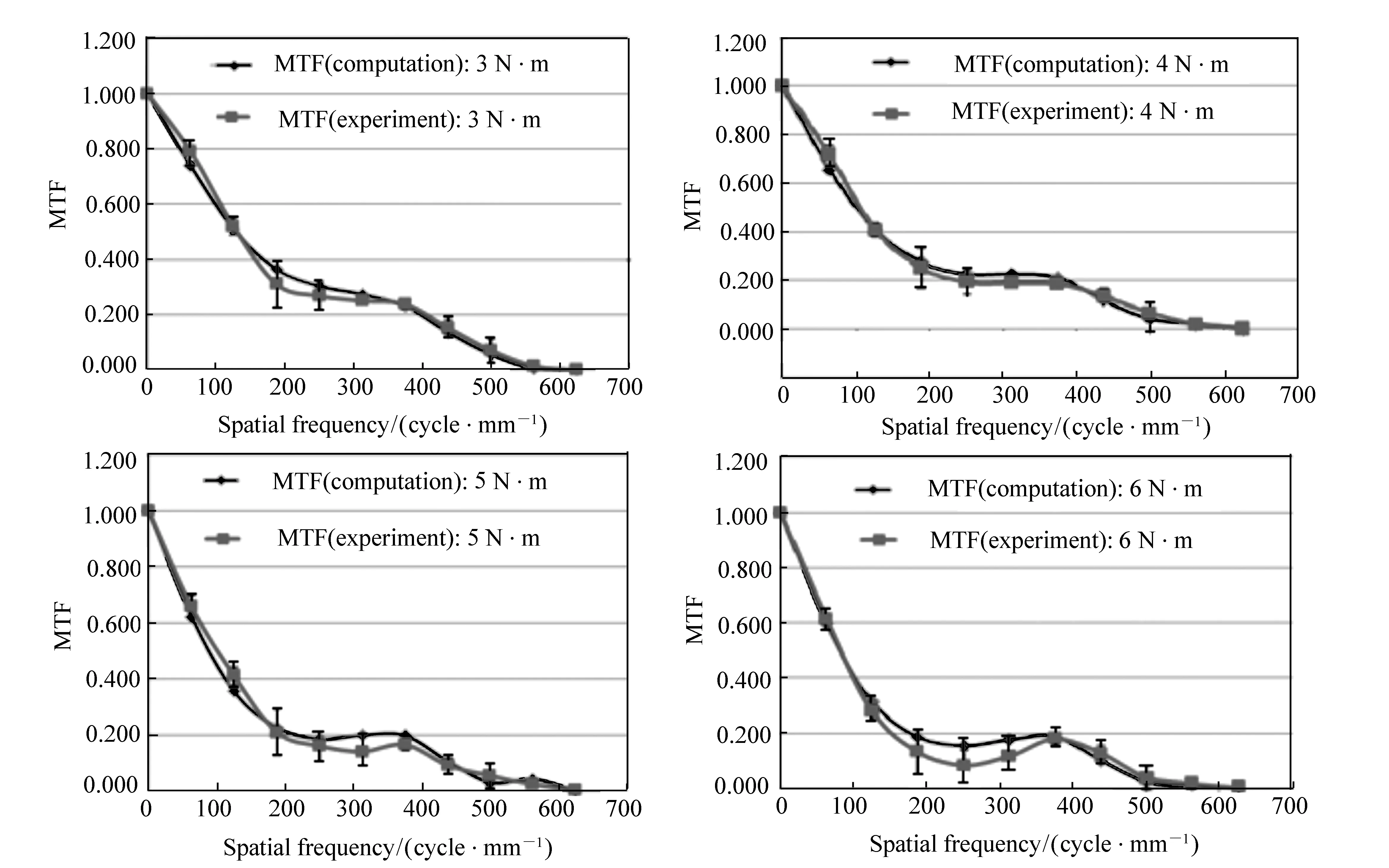
Fig.14 Computed MTF as function of tensile torque(solid circle); experimental MTF as function of tensile torque with deviation 2σ(solid rectangle)
5 Conclusion
This paper presented a detailed methodology capable of predicting the optical performance undergoing static tension applied to the lenses of an opto-mechanical system of high performance. The manuscript also showed the adopted setup used to demonstrate the validity of the methodology using an optical interferometer. Comparison between the computed numerical results and the experimental results assert the exactness of this methodology.
[1] KASUNIC K J.OptomechanicalSystemsEngineering[M]. New Jersey:John Wiley & Sons,Inc.,Hoboken,2015.
[2] SCHWERTZ K,BURGE H.FieldGuidetoOptomechanicalDesignandAnalysis[M] , Bellingham:SPIE Press,2012.
[3] DOYLE K B,GENBERG V L,MICHELSS G J.IntegratedOptomechanicalAnalysis(2nd Edition)[M]. Bellingham:SPIE Press,2012.
[4] KASUNIC K J,BURGE J,YODER P.MountingofOpticalComponents[M]. Bellingham:SPIE Press,2013.
[5] YODER P R. Parametric Investigations of Mounting-Induced Axial Contact Stresses in Individual Lens Elements[J].SPIE,1993,1998:8-20.
[6] SigFit is a product of Sigmadyne,Inc.,Rochester,New York[EB/OL]. http://www.sigmadyne.com.
[7] GENBERG V,DOYLE K,MICHELS G. Making FEA results useful in optical analysis[J].SPIE,2002,4769:24-33.
[8] GENBERG V,DOYLE K,MICHELS G. Opto-Mechanical I/F for ANSYS[R].SigmadyneCompany,2004:TT58.
[9] DOYLE K B,GENBERG V L,MICHELS G J. Integrated optomechanical analysis of adaptive optical systems[J].SPIE,2004,5178:20-25.
[10] DOYLE K B,HOFFMAN J M,GENBERG V L,etal.. Stress Birefringence Modeling for Lens Design and Photonics[J].SPIE,2002,4832:436-447.
[11] DOYLE K,GENBERG V,MICHELS G,etal.. Numerical methods to compute optical errors due to stress birefringenc[J].SPIE,2002,4769:34-42.
[12] BOOTH M,WILSON T,SUN H B,etal.. Methods for the characterization of deformable membrane mirrors[J].AppliedOptics,2005,44(24):5131-5139.
[13] GENBERG V,MICHELS G,DOYLE K. Orthogonality of zernike polynomials[J].SPIE,2002,4771:33-40.
[14]ZemaxManual:OpticalDesignProgramUser′sGuide9-6-2009[M]. ZEMAX Development Corporation.
[15] BUCKLEY-LEWIS D H. Friction behavior of glass and metals in contact with glass in various environments[R],Nasa Technical Note,1973,Nasa TN 0-7529.
Author biographies:
2016-06-16;
2016-07-19
2095-1531(2016)06-0678-09
静态应力作用下预测光学系统性能的计算方法
AL-LAHAM Radwan*, MOUSSELLY Mhd.Fawaz, NAIM Mamoun
(叙利亚应用科学与技术高等学校,大马士革 31983)
本文通过计算预测光学性能的方法表征在光学系统组装和外界环境因素影响下的光学系统灵敏度。该方法即通过调制传递函数来表征静态机械应力对光学物镜性能的影响。采用光学干涉仪对经过加工、组装且存在机械应力的光学物镜进行测试,并比较实验调制传递函数与计算模拟分析的调制传递函数。结果表明,计算结果与实验结果相符,证实了本文方法的有效性。
光学性能预测;光学系统组装;张力转矩;调制传递函数;物镜;Ansys;Matlab
O438
A

AL-LAHAM Radwan(1976—), Master degree. His research interests are on optical design and optical metrology. E-mail:eng.rad.laham@gmail.com
10.3788/CO.20160906.0678