Experimental investigation of influence of strake wings on self-induced roll motion at high angles of attack
2016-11-23GengXiShiZhiweiChengKeming
Geng Xi,Shi Zhiwei,Cheng Keming
College of Aerospace Engineering,Nanjing University of Aeronautics and Astronautics,Nanjing 210016,China
Experimental investigation of influence of strake wings on self-induced roll motion at high angles of attack
Geng Xi,Shi Zhiwei*,Cheng Keming
College of Aerospace Engineering,Nanjing University of Aeronautics and Astronautics,Nanjing 210016,China
The modern high performance air vehicles are required to have extreme maneuverability,which includes the ability of controlled maneuvers at high angle of attack.However,the nonlinear and unsteady aerodynamic phenomena,such as flow separation,vortices interaction,and vortices breaking down,will occur during the flight at high angle of attack,which could induce the uncommanded motions for the air vehicles.For the high maneuverable and agile air missile,the nonlinear roll motions would occur at the high angle of attack.The present work is focused on the selfinduced nonlinear roll motion for a missile configuration and discusses the influence of the strake wings on the roll motion according to the results from free-to-roll test and PIV measurement using the models assembled with different strake wings at α =60°.The free-to-roll results show that the model with whole strake wings(baseline),the model assembled with three strake wings(Case A)and the model assembled with two opposite strake wings(Case C)experience the spinning,while the model assembled with two adjacent strake wings(Case B),the model assembled with one strake wing(Case D)and the model with no strake wing(Case E)trim or slightly vibrate at a certain ‘×”rolling angle,which mean that the rolling stability can be improved by dismantling certain strake wings.The flow field results from PIV measurement show that the leeward asymmetric vortices are induced by the windward strake wings.The vortices would interact the strake wings and induce crossflow on the downstream fins to degrade the rolling stability of the model.This could be the main reason for the self-induced roll motion of the model at α =60°.
1.Introduction
High angle of attack flight capability can extend an aircraft’s aspects of mission performance.The well-known post-stall maneuver technology also requires an air vehicle to achieve controlled maneuvers in the high angle of attack region to increase its agility and maneuverability.However,when flying at high angles of attack,the characteristics of the flow field surrounding the air vehicle are highly unsteady and nonlinear.The unsteady flow phenomena,such as flow separation,vortices formation and breaking down,and asymmetrical shedding of vortices,can induce unsteady aerodynamic loads which would generate the uncommanded motions including wing drop,heavy wing,nose slice and wing rock1for an aircraft.Besides,a missile may experience nonlinear roll motions at high angles of attack too,which was described by Nicolaides.2
One of the most hazardous unwanted motions is the wing rock,which is a self-excited,large-amplitude,limit-cycle oscillation in roll.This unsteady aerodynamic phenomenon was observed in different fighters,such as F-183–5,F-355and X-31.6The wing rock for these aircrafts was generated by the interaction offorebody vortices with strake vortices3or canard vortices.6Ericsson demonstrated that the reason of the wing rock for a slender ogive-cylinder body was the asymmetrical separation switching of the forebody vortices under the ‘moving wall”effect and the wing rock caused by the asymmetric forebody vortices was more severe than that for a slender delta wing.7–9The wing rock for a slender delta wing was experimentally studied by Nguyen et al.for the first time.10According to the experimental results,Ericsson suggested that the leadingedge vortex affected the maximum amplitude of wing rock.11The leading-edge vortex asymmetry could be the source driving the limit cycle oscillations,which was referred in Katz’s review.12It was believed that the wing rock could only be observed for the slender delta wings with sweep angles larger than 75°until the self-induced roll oscillation was captured for a 45°delta wing with round edge by Ueno et al.13–15And the nonzero trim rolling angles were also observed for the nonslender delta wing.The experimental investigation of McClain et al.16demonstrated that the self-induced roll oscillations were observed for not only the thick nonslender delta wing with round leading-edge but also the thin wing with sharp leading-edge.The reattachment lines were suggested to cause these oscillations and the hysteresis of vortices strength was the mechanism to drive the roll oscillations.17Gresham et al.18found that the increase in the slenderness ratio of the wings would suppress the roll asymmetries and oscillations even though the sweep angles were the same.Besides the delta wings,the other planforms of wings,such as rectangular,elliptical and Zimmerman,would generate the self-induced roll oscillations.19–21The particle image velocimetry(PIV)results suggested that the three-dimensional separation bubble may cause the unstable roll at low angles of attack and the loss of reattachment induced the large amplitude roll oscillations at high angles of attack for the rectangular wings with round leading-edge.In general,the forebody vortices,shape of the wing planforms,and shape of the leading-edge profiles could affect the characteristics of the wing rock.Moreover,different orientations of the vertical tail attitude,upright or inverted,could cause different results,which were demonstrated by Johnson and Lind.22
As the demands of close-in air-to-air combat in future,the extreme maneuverability is required for the next-generation air-to-air missiles,which would not avoid the flight in high angle of attack region.At high angles of attack,a cruciformfinned missile could experience nonlinear roll motions,which could in fluence the expected flight trajectory and degrade the hit rate of targets.Compared with the roll motions for wings or aircrafts,there is much less reference focused on missiles though it is important for high maneuverable missiles.The modeling analysis suggested that the rolling moment coeff icient consisted of nonlinear higher order components.23Even the missile was in the symmetrical position,a large rolling moment could be induced by the body vortices or the flow separation on the fins,which was indicated by Meyer.24Recently,a limit-cycle roll oscillation similar to wing rock was observed for a missile with strake wings.25,26The simulation result of Balasubramanian et al.suggested that the asymmetry vortices induced by the wings generated large rolling moment on the fins,which induced the roll27for the missile.
In our previous work,the nonlinear roll motions were observed during the free-to-roll experiments.Both the selfinduced limit-cycle roll oscillation and spinning could occur depending on the angles of attack.28The present work focuses on the unsteady rolling motion occurring at high angle of attack,and the influence of the strake wings is experimentally investigated by dismantling strake wings at V∞=25 m/s in order to better understand the flow physics of the selfinduced roll motions for the cruciform-finned missile with strake wings.Though the wind velocity is much lower than the normal speed of Ma=2–4,the aerodynamic characteristics are still required for extremely maneuverable air-to-air missiles29,and some work was conducted at subsonic velocity.25,29What’s more,some simulation results demonstrated that the velocity of the missile is also within the subsonic range when its angle of attack is higher than α =40°30–32undergoing the post-stall maneuver.The flow structure should be similar if the free stream velocity is under the subsonic velocity.So the present work is meaningful and valuable.
2.Experimental setup
2.1.Wind tunnel and model support system
The experiments were conducted in the Unsteady Wind Tunnel at Nanjing University of Aeronautics and Astronautics.It is a low-speed open-circuit wind tunnel which can operate at speeds from 3 to 30 m/s.The turbulence intensity of the free stream is less than 0.07%.The dimensions of the test section are 1.0 m high,1.5 m wide and 1.7 m long.
A dynamic test system,the five-degree-of-freedom dynamic test mechanism,33was used to support the model for the present experiment.The test mechanism consists of a forced roll test sting which is used for force measurement,and a free-toroll test sting which is used to observe and record the roll motions in time history.These stings can be exchanged for different experiments.
2.2.Model
The model used in the present experiment was a cruciformfinned missile with in-line strake wings.Each of the strake wings can be assembled independently.The length of the model is l=500 mm,and the diameter is Dia=30 mm.The detailed geometries of the baseline model are shown in Fig.1(a).In order to study the influence of the strake wings on the roll motions at high angles of attack,the models assembled with different numbers of strake wings were tested in this paper.Fig.1(b)–(g)presents the different cases of models.All cases of the models are presented at the front view and φ =0°.The baseline model consists of total four strake wings.Case A dismantles the up vertical strake wing,Case B dismantles the up vertical strake wing and the right horizontal strake wing,Case C dismantles the two vertical strake wings,Case D only assembles the right horizontal strake wing,and Case E dismantles all the strake wings.

Fig.1 Geometries of model and models with strake wings dismantled.
2.3.PIV system
The quantitative results of the flow field were obtained by a two-component PIV system.Images were acquired and processed using a LaVision PIV system.A Beamtech Vlite 200 Nd:YAG double-pulse laser was used to form a thin light sheet for PIV measurement.The wavelength of the laser was 532 nm.The images were captured by a LaVision 2048×2048 pixel Imager Pro-X charge-coupled-device(CCD)camera equipped with a Nikon Nikkor AF 50 mm f1.8D lens.Each image pair was divided into a decreasing interrogation window size of 642-322pixel2multipass processing with 50%overlap and processed with a cross-correlation algorithm using DaVis 7.2 software.Then,postprocessing was used to remove spurious vectors using an allowable vector range and median filter for the resulting velocity fields.A 3×3 Gaussian smoothing filter was also applied to the velocity fields’calculation.The PIV system setup is shown in Fig.2(a).The measurement planes were perpendicular to the longitude axis and above the leeward side of the models,where the locations were X=220 mm,X=290 mm,X=340 mm,X=400 mm and X=480 mm measured from the apex of the model for all the cases(Fig.2(b)).All the results from PIV measurement were static and averaged using 100 pairs of images in the present paper.
3.Results and discussion

Fig.2 Sketch of PIV setup and measurement planes.
As being captured in the previous work,the baseline model generated nonlinear roll motions.Increasing the angle of attack from low to high,the model experienced trimming at‘‘+” shaped equilibrium positions,trimming at ‘×” shaped equilibrium positions,self-induced oscillation and spinning in the experimental free-to-roll conditions.The present work focuses on the self-induced spinning at α=60°and discusses the influence of the strake wings on the roll motion depending on the flow patterns.The freestream velocity maintained at V∞=25 m/s and the angle of attack maintained at α =60°for all the tests.
3.1.Free-to-roll test
The variations of rolling angle in time history of different cases are presented in Fig.3.For the baseline as shown in Fig.3(a),the model spins immediately after being released rolling free from the ‘+” shaped position of φ =0°(black curve).If being released from the ‘×” shaped position of φ =45°(red curve),the model begins to generate the oscillation about φ =45°and the amplitude of the oscillation continues to increase.Subsequently the oscillation develops into spinning.For Case A,the roll motions are similar to the baseline.When being released from the ‘+” position(black curve),the model begins to spin immediately.When being released from the ‘×”position(red curve),the oscillation is induced firstly.Then the motion develops into the spinning as the result of increase in the oscillation amplitude(Fig.3(b)).For Case B,only two adjacent strake wings are assembled.Being released from φ =0°(black curve),the model generates the damping oscillation about φ=-140°immediately.Astheamplitude decreases to zero,the model trims at φ =-140°where the two adjacent strake wings are on the leeward side of the model.If being released from φ =45°(red curve),the model trims at the initial rolling angle,where the two strake wings are on the windward side of the model(Fig.3(c)).The simplified geometry of the equilibrium positions is also presented in Fig.3(c).However,the spinning is generated after the model is released rolling free when two strake wings are mounted on the opposite sides for Case C(Fig.3(d)).For Case D,the model vibrates slightly at φ ≈ -135°after being released from φ =0°(black curve)or φ =45°(red curve),and the simplified geometry of the equilibrium positions is shown in Fig.3(e).For Case E,as can be observed in Fig.3(f),the model oscillates and amplitude decreases after being released from the‘‘+” position of φ =0°(black curve)and vibrates slightly at φ =-135°at last.If the model is released from the ‘×”position of φ =-45°(red curve),the model vibrates slightly at the initial rolling angle and cannot generate the large amplitude oscillation.The simplified geometry of the equilibrium positions is also presented in Fig.3(f).
The free rolling results in Fig.3 have shown that the spinning is generated at α =60°for Case A and Case C besides the baseline.The rolling stability is not be improved for Case A and Case C.For Case B,Case D and Case E,it seems that the model’s rolling stability is improved because the model trims or vibrates slightly at a certain ‘×”position rolling angle and no oscillation or spinning is generated.The different roll motions for different cases indicate that the strake wings affect the rolling stability of the model significantly.An interesting phenomenon is that the model is assembled with two strake wings for both Case B and Case C but in the different locations.For Case B,the two strake wings are adjacent,and for Case C,the strake wings are opposite.Because of the different locations where the strake wings are mounted,different roll motions are observed for the two cases.This suggests that the positions of the strake wings could influence the rolling stability of the model.
3.2.Flow field
The roll motions of different cases were observed,and in order to better understand the in fluence of the strake wings in flow physics,the PIV measurement was conducted to obtain the flow pattern at different rolling angles for each case.The static PIV results are discussed in this paper.In this paper ωXrepresents the vorticity.

Fig.3 Rolling angle in time history for different cases.
Fig.4 shows the streamlines and normalized vorticity for baseline at φ =0°and φ =45°.A pair of vortices are observed above the leeward surface of the strake wings on the two sides of the model at the position of X=220 mm and φ =0°.The right(view from the front of the model)vortex is better formed and is larger in size than the left one.At X=290 mm,there is a small vortex above the leeward surface of the right strake wing.At X=340 mm,only a vortex is observed above the left leeward side of the model and it almost sheds from the model.The vortices are induced by the strake wings and they are asymmetric though the model is in a symmetrical position.At X=400 mm,the crossflow can be indicated by the streamlines above the leeward side of the model,which could be induced by the upstream asymmetric vortices.At downstream location X=480 mm,the streamlines indicate that there is cross flow on the fins,which could also be induced by the upstream asymmetric vortices.And the stability efficiency of the fins seems to decrease as the flow separates on the leeward surface of the fins at high angle of attack.In general,the flow field above the leeward side of the model is highly asymmetric at φ =0°which is the ‘+” position.As a result,rolling moment could be generated on the strake wings and fins,which makes the model’s rolling unstable at the position.At the ‘×” position of φ =45°,there are two strake wings on the windward side of the model and two on the leeward side of the model.Above the leeward strake wings,the flow field mainly consists of a pair of vortices and the two vortices are asymmetric.It seems that the vortices in each cross section arenewlyformedatX=220 mm,X=290 mm and X=340 mm.The vortices would shed from the body and new ones would be generated above the downstream leeward strake wings,which affects the downstream flow field asymmetrically above the strake wings.Because of the asymmetric and unstable vortices induced by the strake wings,the rolling moment could be generated to make the model unstable in the free rolling condition.Though the stability efficiency of the fins seems to be more efficient than the one at φ =0°,it may be still too low to keep the model stable as the vortices do not form well(Fig.4(b)).Consequently,the model cannot trim at the ‘×”position of φ =45°and roll motion is induced.As shown in Fig.4,the vortices induced by the strake wings are asymmetric at both the symmetric position φ =0°and φ =45°.As a result,the unsteady roll motion,which is spinning,is induced at α =60°for baseline.
The flow fields for Case A at different rolling angles are presented in Fig.5.At φ =0°,asymmetric vortices are seen above the leeward side of the model and the vortices shed from the body easily.The crossflow can be seen above the leeward side ofthemodelatX=400 mm andabovethefinsat X=480 mm,which is similar to the baseline.Compared with Fig.4(a),the flow pattern of Case A is quite similar to the baseline at the measured planes generally.So the model cannot keep stable at this rolling angle.As shown in Fig.5(b),the flow pattern is similar to the baseline at φ =45°despite the negligible difference too.Though a strake wing is dismantled from the left leeward side of the model at φ =45°,it does not affect the flow field significantly.More details can be observed in Fig.5(b)that there are two small but strong vortices beside the model separately at X=290 mm.The left vortex increases in the size when it develops at X=340 mm and it is still strong.The right vortex does not get as strong as the left one at X=340 mm and its core’s position is lower than the left one.This could be affected by the leeward strake wing on the right side of the model.When the model rolls to φ =90°,there is no strake wing on the left side of the model(Fig.5(c)).At this rolling angle,the flow field is much more asymmetric than the one at φ =0°or φ =45°because of the asymmetric geometry.There are vortices above the leeward surface of the right strake wing which may be induced by the strake wing.In the left part of the model,no vortex can be observed evidently,which is different from the situation in Fig.4(a)or Fig.5(a).However,the streamlines at X=480 mm are similar to those in Fig.4(a)or Fig.5(a).This flow pattern indicates the cross flow above the fins and the decrease in the stability efficiency of the fins.The asymmetric vortices above strake wings and the cross flow above the fins would generate the rolling moment that makes the model roll.According to the results from Case A,it can be inferred that the vortices above the leeward side of the model could be induced by the windward strake wings.
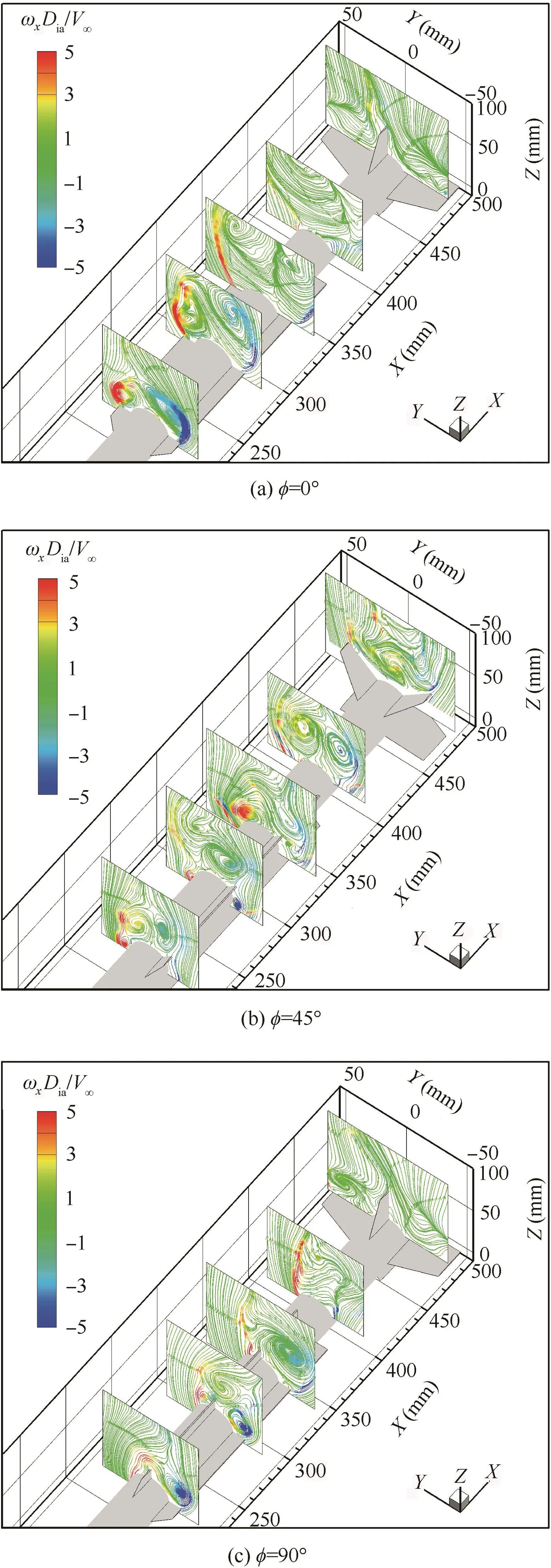
Fig.5 Normalized vorticity and streamlines for Case A at different rolling angles.
Fig.6 shows the flow field results for Case B at different rolling angles.For Case B,there are two adjacent strake wings assembled on the model.At φ =0°shown in Fig.6(a),a strake wing is on the windward side of the model,and the other one is on the left side.The left strake wing induces the vortices above its leeward surface,which can be observed at X=220 mm,X=290 mm and X=340 mm.Though there is no strake wing on the right side of the model,the vortices are formed above the model leeward.And the vortices on the right side are not as strong as the vortices on the left side,which can be observed at X=220 mm and X=290 mm.The right vortices may be induced by the model’s cylinder body.At X=480 mm,the streamlines also indicate the cross flow on the fins.The flow field is highly asymmetric at φ =0°for Case B.Consequently the model cannot trim at φ =0°when released rolling free.If comparing Fig.6(a)with Fig.5(c),we can see that the flow pattern in Case B at φ =0°is converse to the one in Case A at φ =90°approximately.The obvious difference is that there is a vortex above the model’s leeward side at X=220 mm in Case B but none in Case A.The difference may be because of the suppression of the strake wing on the leeward side of the model in Case A.Fig.6(b)shows the flow pattern at φ =45°for Case B.At this rolling angle,both the two adjacent strake wings are on the windward side of the model.At X=290 mm,there is one small strong vortex to form above the leeward side of each strake wing.It can be inferred that the vortices above the leeward side of the model may be induced by the windward strake wings.Though the model is at a symmetrical position,the vortices above the leeward side are asymmetric.However,the free rolling result in Fig.3(c)shows that the model trims at φ =45°.There different motion phenomena may be because of different con figurations.For Case B at φ =45°,there is no strake wings on the leeward side of the model for the asymmetric vortices to generate rolling moment.Besides,the stability efficiency of the‘×” fins is better than the ‘+” fins because they have smaller effective angle of attack to generate smaller flow separation region at high angle of attack,which can be inferred from the flow field.These two factors could be the reason why the model can trim at φ =45°.The other rolling angle the model can trim at is φ =-135°and Fig.6(c)shows the flow pattern at the angle.At φ =-135°,the two adjacent strake wings are on the leeward side of the model.A pair of vortices can be observed above the leeward strake wings at X=220 mm,X=290 mm,X=340 mm and X=400 mm.These leeward vortices are much more symmetrical than the baseline and it seems that they do not induce cross flow on the leeward fins’flow field downstream.Because of the approximately symmetrical vortices above the leeward strake wings,the model can trim at φ =-135°after being released rolling free.

Fig.6 Normalized vorticity and streamlines for Case B at different rolling angles.

Fig.7 Normalized vorticity and streamlines for Case C at different rolling angles.
The flow field results at different rolling angles for Case C are shown in Fig.7.In this case,the two strake wings are at the opposite positions on the model.As Fig.7(a)shows the flow pattern when the model is at φ =0°,the asymmetric vortices are induced above the leeward surfaces of the strake wings.Because of the in fluence of the upstream vortices,the obvious cross flow can be seen at the measured plane at X=400 mm and above the fins at X=480 mm.The flow field shown in Fig.7(a)is quite similar to the one shown in Fig.4(a)though there is no strake wing in the vertical position on the model for Case C.Also,it is similar to the flow pattern in Case A at φ =0°shown in Fig.5(a).It is inferred from the comparison that the vortices may be induced by the strake wings on the two sides of the model and they are generated above the leeward surfaces of the strake wings.It seems that the vertical strake wing on the neither windward nor leeward side of the model has little contribution to the formation of the vortices.Because of the similar flow field to baseline and Case A,the model cannot trim at φ =0°in Case C.The flow pattern for Case C at φ =45°is presented in Fig.7(b).At this rolling angle,a strake wing is on the windward side of the model and the other is on the leeward side.The windward strake wing induces the vortices on the left leeward side of the model,which is similar to the flow pattern shown in Fig.5(b).On the right leeward side of the model,there are vortices which can be observed above the strake wing.The vortices would generate unstable rolling moment on the leeward surface of the strake wing.As a result,the model cannot trim at φ =45°.Fig.7(c)shows the flow pattern for Case C at φ =90°where the two opposite strake wings are on the vertical position.At this rolling angle,the asymmetric vortices can beobserved abovetheleeward sideofthemodelat X=220 mm,X=290 mm,X=340 mm and X=400 mm.The vortices may be induced by the model body because there is no strake wing on the two sides of the model,which is different from the situation at φ =0°.At X=480 mm,though no evident cross flow is observed,the flow separation occurs on the leeward side of the fins,which decreases the stability efficiency of the fins.Consequently,the model is unstable in the rolling direction at φ =90°too.
Fig.8 presents the flow field results at different rolling angles for Case D.In this case,there is only one strake wing assembled on the model.At φ =0°,the only one strake wing is on the right side of the model.The vortices form above the leeward surface of the strake wing,which is similar to the Case A at φ =90°(Fig.5(c)).There are vortices which can be seen on the right leeward side of the model.It may be the model’s body that generates these vortices.Being affected by the upstream asymmetric vortices,the cross flow is induced on the leeward fins,which is similar to the other cases and makes the model unstable at φ =0°.At φ =45°,the strake wing is on the right leeward side of the model.The asymmetric vortices may be induced by the model’s body too(Fig.8(b)).Because there is a strake wing on the right leeward side of the model,the vortices would generate rolling moment on the strake wing,which breaks the rolling stable state at φ =45°.Consequently,the model cannot trim at φ=45°after being released from this rolling angle(Fig.3(e)).When the model is at φ =90°,the strake wing is vertical on the leeward model.The asymmetric vortices can still be observed in the flow field.It may be the model’s cylinder body that induces these asymmetric vortices(Fig.8(c)).Different from the situation shown in Fig.8(a),the asymmetric vortices do not induce the cross flow on the leeward fins.However,the unsteady flow separation occurs on the leeward surface of the fins,which degrades their stability efficiency.Consequently,φ =90°is not an equilibrium position for the model in this situation.At φ =-135°(Fig.8(d)),which is an equilibrium position that has been demonstrated in Fig.3(e),the strake wing is on the left windward side of the model.Though the asymmetric vortices are induced on the leeward side of the model,there is no strake wing on the leeward side for the asymmetric vortices to generate the rolling moment.For the ‘×” fins,the flow separation region is smaller than that of the ‘+” fins at high angle of attack.And the fins’effective angle of attack is smaller when the fins are ‘×” shaped,which means the better efficiency of the fins at high angle of attack.So the ‘×” fins are more stable than the ‘+” fins.That is why the model can trim at φ =-135°rather than φ =90°.
Fig.8 Normalized vorticity and streamlines for Case D at different rolling angles.
The flow fields for Case E without strake wing are shown in Fig.9.In this case,the asymmetric vortices are observed on the leeward model too.There are mainly two vortices on each measured plane at X=220 mm,X=290 mm,X=340 mm and X=400 mm.It can be inferred that the vortices are induced by the model’s cylinder body instead of strake wings.The flow patterns above the leeward model at the rolling angles of φ =0°and φ =45°are similar to each other because of the same geometry of the model’s body.At X=480 mm,where the measurement plane is above the leeward fins,the obvious difference can be found between the two rolling angles.At φ =0°,flow separation occurs on the leeward surface of the fins.Though the flow separation also occurs on the leeward fins at φ =45°,the separation range is smaller than that at φ =0°.Besides,the ‘×” fins with smaller effective angle of attack has better stability efficiency at high angle of attack.That may be the reason why the ‘×” rolling angles are the equilibrium positions in Case E.What’s more,if we compare Fig.9(a)with Fig.8(c),the vortices in Case E form better than those above the strake wing in Case D.The difference may be caused by the vertical leeward strake wing in Case D where the vertical leeward strake wing may suppress the vortices.
Figs.4–9 present the flow fields mainly above the leeward after body of the model for the different cases and different rolling angles at α =60°.Demonstrated in these flow patterns,the roll motion is related to the asymmetric vortices induced by the strake wings.As a conjecture,the shear layer shedding from the windward strake wings which have efficient angle of attack between the free streams,rolls to the leeward side of the model to generate the vortices.This can be inferred by the approximately similar flow pattern shown in Fig.4(a),Fig.5(a)and Fig.7(a),Fig.4(b)and Fig.5(b),Fig.5(c)and Fig.8(a),and Fig.8(b)and Fig.9(b).The approximately converse flow pattern,shown in Fig.5(c)and Fig.6(a),and Fig.6(a)and Fig.8(a),can also indicate that the vortices may be mainly induced by the windward strake wings.However,the vortices are asymmetric during the development and may impact the leeward strakewingstogeneratetheunstablerollingmomentonthesurfacesoftheleewardstrakewings,whichcanbeinferredfromthe similar leeward flow field but different free rolling phenomena between Case D and Case E at φ =45°.The induced rolling moment could break the equilibrium state of the model in rolling.Besides the induced rolling moment,the crossflow induced by the upstream asymmetric vortices impacts fins,which may makethemodelroll.Inaddition,thelargeregionoftheflowseparation occurring on the leeward surfaces of the fins degrades the rolling stable efficiency of the fins at high angle of attack,especially for the ‘+” fins,which is indicated by the difference offlow pattern between Fig.9(a)and(b).To summarize,the asymmetric vortices induced by the strake wings may be the mainreasonforthemodel togeneratetheunsteadyrollmotions at high angle of attack.It can be inferred that the roll motions can be suppressed by weakening the influence of the vortices induced by the strake wings on the downstream fins or modifyingtheflowfieldabovetheleewardsideofthestrakewingstobe symmetric.

Fig.9 Normalized vorticity and streamlines for Case E at different rolling angles.
The flow patterns shown in the present paper are all static results.The static flow field illustrates the basic aerodynamic characteristics of the model.There is no doubt that the steady flow field is different from the unsteady one.However,it should be similar to each other.The difference in the unsteady flow field is the hysteresis,which is the structure’s development lag in time and space.At the beginning of the unsteady motion or the moment when model is released free,the flow field can be treated as steady or quasi-steady.When the model trims at a certain rolling angle or vibrates,the flow field can also be treated as steady.So the static results can be used to discuss the reason why the model begins to roll or trims at a certain rolling angle.
4.Conclusions
The influence of the strake wings on the unsteady roll motion,the spinning,was investigated using free-to-roll test and PIV measurement focusing on a missile configuration model at α=60°in the present work.The free-to-roll test of the different cases of the model assembled with different strake wings demonstrates that the baseline,Case A and Case C would generate spinning in the free rolling condition,while Case B,Case D and Case E would trim or slightly vibrate at a certain ‘×”rolling angle.The flow field results from PIV measurement show that the flow field mainly consists of asymmetric vortices which may be induced by the windward strake wings.The asymmetric vortices would in fluence the leeward strake wings to generate the rolling moment and induce the cross flow on the downstream fins to degrade the stability efficiency of the fins.Also,the flow separation occurring on the fins would degrade the stability efficiency.
The interaction between the strake wings and surrounded flow field seems to be the main reason to induce the unsteady roll motion for the missile at high angle of attack.This should be carefully considered in the aerodynamic design of the highly maneuverable missile to avoid the unwanted roll motions at high angle of attack.The present work only discusses the static flow field of the model.The details of the dynamic development of the flow field during the roll motion should be obtained to better understand the flow physics of the unsteady motions in the future.
1.Nelson RC,Pelletier A.The unsteady aerodynamics of slender wings and aircraft undergoing large amplitude maneuvers.Prog Aerosp Sci 2003;39(2–3):185–248.
2.Nicolaides JD.Missile flight and aerodynamics.Washington,DC:Bureau of Naval Weapons;1961,Report No.:TN-100-A.
3.Quast T,Nelson RC,Fisher DF.A study of high alpha dynamics and flow visualization for a 2.5%model of the F-18 HARV undergoing wing rock.Reston:AIAA;1991,Report No.:AIAA-91-3267.
4.Owens DB,Capone FJ,Hall RM,Brandon JM,Cunningham K,Chambers JR.Free-to-roll analysis of abrupt wing stall on military aircraft at transonic speeds.Reston:AIAA;2003,Report No.:AIAA-2003-0750.
5.Owens DB,McConnell JK,Brandon JM,Hall RM.Transonic free-to-roll analysis of the F/A-18E and F-35 configurations.Reston:AIAA;2004,Report No.:AIAA-2004-5053.
6.Williams II DL,Nelson RC,Fisher DF.An investigation of X-31 roll characteristics at high angle-of-attack through subscale model testing.Reston:AIAA;1994,Report No.:AIAA-94-0806.
7.Ericsson LE.Wing rock generated by forebody vortices.J Aircraft 1989;26(2):110–6.
8.Ericsson LE.Further analysis of wing rock generated by forebody vortices.J Aircraft 1989;26(12):1098–104.
9.Ericsson LE,Mendenhall MR,Perkins Jr SC.Review offorebodyinduced wing rock.J Aircraft 1996;33(2):253–9.
10.Nguyen LT,Yip L,Chambers JR.Self-induced wing rock of slender delta wings.Reston:AIAA;1981,Report No.:AIAA-81-1883.
11.Ericsson LE.Wing rock analysis of slender delta wings,review and extension.J Aircraft 1995;32(6):1221–6.
12.Katz J.Wing/vortex interactions and wing rock.Prog Aerosp Sci 1999;35(7):727–50.
13.Ueno M,Matsuno T,Nakamura Y.Unsteady aerodynamics of rolling thick delta wing with high aspect ratio.Reston:AIAA;1998,Report No.:AIAA-98-2520.
14.Matsuno T,Nakamura Y.Self-induced roll oscillation of 45 degree delta wings.Reston:AIAA;2000,Report No.:AIAA-2000-650.
15.Matsuno T,Yokouchi S,Nakamura Y.The effect of leading-edge profile on self-induced oscillation of 45-degree delta wings.Reston:AIAA;2000,Report No.:AIAA-2000-4004.
16.McClain A,Wang Z,Vardaki E,Gursul I.Unsteady aerodynamics offree-to-roll nonslender delta wings.Reston:AIAA;2007,Report No.:AIAA-2007-1074.
17.Gresham NT,Wang Z,Gursul I.Vortex dynamics offree-toroll slender and nonslender delta wings.J Aircraft 2010;47(1):292–302.
18.Gresham NT,Wang Z,Gursul I.Effect of slenderness ratio on free-to-roll wing aerodynamics.J Aircraft 2011;48(3):1112–5.
19.Gresham NT,Wang Z,Gursul I.Aerodynamics offree-to-roll low aspect ratio wings.Reston:AIAA;2009,Report No.:AIAA-2009-543.
20.Gresham NT,Wang Z,Gursul I.Self-induced roll oscillations of nonslender wings.AIAA J 2009;47(3):481–3.
21.Gresham NT,Wang Z,Gursul I.Low Reynolds number aerodynamics offree-to-roll low aspect ratio wings.Exp Fluids 2010;49(1):11–25.
22.Johnson B,Lind R.Characterizing wing rock with variations in size and configuration of vertical tail.J Aircraft 2010;47(2):567–76.
23.Cohen CJ,Clare TA,Stevens FL.Analysis of the nonlinear rolling motion offinned missiles.AIAA J 1974;12(3):303–9.
24.Meyer J.Effects of the roll angle on cruciform wing-body configurations at high incidences.J Spacecraft Rockets 1994;31(1):113–22.
25.Da XY,Zhao ZL,Tao Y,Yang HY.Experimental investigation on free-to-roll motion of strake missile.J Exp Fluid Mech 2012;26(6):40–3[Chinese].
26.Da XY,Tao Y,Zhao ZL.Numerical simulation of virtual flight based on prediction-correction coupling method and chimera grid.Acta Aeronautica et Astronautica Sinica 2012;33(6):977–83[Chinese].
27.Balasubramanian R,Shah V,Arora K,Krishnamurthy K,Chakraborty D.Numerical investigations of lateral characteristics of an air-to-air missile.J Aircraft 2013;50(1):88–95.
28.Geng X,Shi ZW,Cheng KM,Gong Z,Liu C.Rolling stability analysis of missile with strake wing.Acta Aeronautica et Astronautica Sinica 2015;25(10):3241–8[Chinese].
29.Honkanen T,Tuisku T,Pankkonen A.CFD simulations and wind tunnel experiments of a generic split-canard air-to-air missile at high angles of attack in turbulent subsonic flow.Reston:AIAA;2011,Report No.:AIAA-2011-6335.
30.Kim K,Kang S,Kim HJ,Lee CH,Tahk MJ.Realtime agile-turn guidance and control for an air-to-air missile.Reston:AIAA;2010,Report No.:AIAA-2010-7745.
31.Yan L,Ma KM,DongJ P,Zhang JP.Design of over-the-shoulder launch control for air-to-air missiles with lateral jets.Aero Weaponry 2013;06:3–8[Chinese].
32.Ma Y,Guo J,Tang S.High angle of attack command generation technique and tracking control for agile missiles.Aerosp Sci Technol 2015;45:324–34.
33.Geng X,Shi Z,Cheng K,Li L.A new hybrid mechanism for dynamic wind tunnel test of high maneuverable air vehicle.Proc Inst Mech Eng,Part G:J Aerospace Eng[Online].
Geng Xi is a Ph.D.student at College of Aerospace Engineering,Nanjing University of Aeronautics and Astronautics.He received his B.S.degree from the same university in 2009.His main research interests are experimental aerodynamics,unsteady aerodynamics,and flow control.
Shi Zhiwei is a professor and Ph.D.supervisor at College of Aerospace Engineering,Nanjing University of Aeronautics and Astronautics.He received his B.S.,M.S.and Ph.D.degrees from the same university.His current research interests are unsteady aerodynamics, flow control with plasma actuators,and micro aerial vehicles.
Cheng Keming is a professor and Ph.D.supervisor at College of Aerospace Engineering,Nanjing University of Aeronautics and Astronautics.His current research interests are high speed aerodynamics and flow control.
22 December 2015;revised 28 March 2016;accepted 9 May 2016
Available online 24 October 2016
Cruciform fins;
High angle of attack;
PIV;
Roll motion;
Strake wing
Ⓒ2016 Chinese Society of Aeronautics and Astronautics.Production and hosting by Elsevier Ltd.This is anopenaccessarticleundertheCCBY-NC-NDlicense(http://creativecommons.org/licenses/by-nc-nd/4.0/).
*Corresponding author.
E-mail addresses:greatgengxi@hotmail.com(X.Geng),szwam@nuaa.edu.cn(Z.Shi),cheng.km@nuaa.edu.cn(K.Cheng).
Peer review under responsibility of Editorial Committee of CJA.
Production and hosting by Elsevier
http://dx.doi.org/10.1016/j.cja.2016.09.008
1000-9361Ⓒ2016 Chinese Society of Aeronautics and Astronautics.Production and hosting by Elsevier Ltd.
This is an open access article under the CC BY-NC-ND license(http://creativecommons.org/licenses/by-nc-nd/4.0/).
杂志排行

CHINESE JOURNAL OF AERONAUTICS的其它文章
- Analysis of swirling flow eff ects on the characteristics of unsteady hot-streak migration
- Implicit discontinuous Galerkin method on agglomerated high-order grids for 3D simulations
- Design and implementation of rigid-flexible coupling for a half-flexible single jack nozzle
- Dynamic simulation of aerial towed decoy system based on tension recurrence algorithm
- A quasi-one-dimensional model for hypersonic reactive flow along the stagnation streamline
- An experimental investigation on static directional stability