Simulative technology for auxiliary fuel tank separation in a wind tunnel
2016-11-23MaXinLiuWeiChenLingLiXiaoJiaZhenyuanShangZhiliang
Ma Xin,Liu Wei,Chen Ling,Li Xiao,Jia Zhenyuan,Shang Zhiliang
Key Laboratory for Precision and Non-traditional Machining Technology of the Ministry of Education,Dalian University of Technology,Dalian 116024,China
Simulative technology for auxiliary fuel tank separation in a wind tunnel
Ma Xin,Liu Wei*,Chen Ling,Li Xiao,Jia Zhenyuan,Shang Zhiliang
Key Laboratory for Precision and Non-traditional Machining Technology of the Ministry of Education,Dalian University of Technology,Dalian 116024,China
In this paper,we propose a simulative experimental system in wind tunnel conditions for the separation of auxiliary fuel tanks from an aircraft.The experimental system consists of a simulative release mechanism,a scaled model and a pose measuring system.A new release mechanism was designed to ensure stability of the separation.Scaled models of the auxiliary fuel tank were designed and their moment of inertia was adjusted by installing counterweights inside the model.Pose parameters of the scaled model were measured and calculated by a binocular vision system.Additionally,in order to achieve high brightness and high signal-to-noise ratio of the images in the dark enclosed wind tunnel,a new high-speed image acquisition method based on miniature self-emitting units was presented.Accuracy of the pose measurement system and repeatability of the separation mechanism were verified in the laboratory.Results show that the position precision of the pose measurement system can reach 0.1 mm,the precision of the pitch and yaw angles is less than 0.1°and that of the roll angle can be up to 0.3°.Besides,repeatability errors of models' velocity and angular velocity controlled by the release mechanism remain small,satisfying the measurement requirements.Finally,experiments for the separation of auxiliary fuel tanks were conducted in the laboratory.
1.Introduction
It is an important capability for military aircraft in flight to release external stores such as weapons and auxiliary fuel tankswhen necessary.However,due to the interaction between the aerodynamic environment and dynamical characteristics of the external stores,the released store may collide into the aircraft,threatening the regular performance of the aircraft and the safety of the pilot.Therefore,it is of great significance to conduct safety research for the separation of external stores during the design and service process of the aircraft.The commonly-used captive trajectory simulation(CTS)system is used to simulate the trajectory of external stores(such as missiles bombs and auxiliary fuel tanks)after they are separated from an aircraft,which helps to guide the proper arrangement of stores on the plane,as well as the control of stores' release parameters.1Among many research methods,the free drop method is one of the most typical experimental methods for store separation simulations in wind tunnels.The free drop method,with which the external store is ejected from the aircraft,falls down freely,and the trajectory of the external store is captured by high-speed cameras,has been widely used in simulative experiments for flight testing.
Traditionally,the free drop experiment system for store separation in wind tunnel mainly includes a separation system and a high-speed measuring system.Currently,the simulative separation system mainly consists of a suspending mechanism and an ejection mechanism.In 2008,Johnson proposed a separation system for external stores using an explosive bolt to ensure suspension and a double-spring loading device to provide the load.2When the ejection signal came,the explosive bolt ruptures by being energized.Meanwhile,the store was ejected by the ejection load provided by the springs.With this strategy,the initial kinematic parameters of the store could be adjusted by changing the preload of the springs,thus pose characteristics of the store were under control.However,since the ejection load came from springs,constraints would occur because the characteristics of the springs such as the elastic coefficient were limited to a small range.
In 2009,Murray et al.in the University of Mississippi presented an ejection system based on double-cylinder loading and ball brake suspending.3The store model was firstly retained on the pylon by the ball brake,then it would be ejected by the double-cylinder loading device triggered by the releasing signal.The system provided adjustable release force as well as velocity with intense adjustment,and was highly repeatable.However,it was difficult to control the two cylinders simultaneously and the system maintenance would be a tough job with its complex configuration.The EDO Corporation developed a vertical ejection device with a multi-linkage mechanism and a cylinder as the power producer.4Making the best of the precisely calculated and optimized linkages,the system was capable of controlling parameters such as the initial systemic velocity,acceleration,angle and angular velocity of the store at a given air pressure and flow.Unfortunately,the system was mainly designed for the ejection of buried stores instead of external stores,because the pylon under the wing was too small to contain a multi-linkage mechanism during the separation experiment in the wind tunnel.Additionally,some of the linkages were likely to extend outside the plane,affecting the air flow field of the test section,which might cause errors in the result.Guan and Cai indicated that spoilers are capable of controlling the flow pattern inside the plane cabin,which helps to guide the control of yaw angles of buried stores.5However,the study does not cover all the release characteristics(both the position and attitude)of the store,which is difficult to meet the measurement requirements discussed in this paper.
When it comes to pose measurement of aircraft stores,high-speed cameras are usually applied to capturing the 2D images of the target and pose parameters can be obtained by analyzing those images.In the early 1960 s,the dynamic similitude method was firstly utilized to study the separation characteristics of stores.It mainly adopted a multiple-exposure method to record the pose and trajectory of the target in the same film and subsequent analysis was based on that film.The scheme is widely used owing to its simplicity and less refits to the original wind tunnel facilities.The method presents a simple method for qualitative observations and store separation studies.But large errors may occur when it comes to quantitative analysis due to the insufficient information in one single image.A video model deformation(VMD)method has been developed and applied by NASA on the basis of model deformation measurement.6–9VMD was based upon digital photogrammetry using recorded and processed digitized video images from a CCD camera.A single-camera,single-view photogrammetry was applied to determining object plane coordinates and angles corresponding to retro-reflective markers placed at known locations.10Though the method helps to achieve a non-contact,flexible and real-time measurement of the model,wind tunnels with small space are not able to conduct the experiment since a high-power light source is required for the retro-reflective markers.The commercially available OptotrakTMsystem measuring the aeroelastic deformation and the angle of attack of planes was produced by Northern Digital Incorporated(NDI)of Ontario,Canada.11Small infrared emitting diodes(IREDs),instead of reflective markers,are employed as markers which are mounted rigidly in or on the object to be measured.Then high-speed cameras are employed to capture the images of the target.Using the OptotrakTMsystem,wind tunnels with low brightness are also capable of conducting the measurement and a light source was no longer required.Disadvantages lie in the inability to measure the over-all parameters except for aeroelastic deformation and angle of attack.Other methods employ cooperating markers attached to the model surface to serve as feature points,such as the single camera method proposed by Martinez et al.12and the pose measurement for high-speed rolling targets proposed by Jia et al.13Retro-reflective targets and a high-power light source were used in their experiment.Both of the above methods have achieved efficient pose measurement of the targets.However,the quality and signal to noise ratio(SNR)of the images were decreased due to the strong light reflection from the observation window.
Here,we design a simulative separation and measurement system for the free drop experiment of external stores in a transonic wind tunnel.This paper is organized as follows:Section 2 introduces the simulated release mechanism of an auxiliary fuel tank and the scaled model according to the geometric and dynamic characteristics of an actual auxiliary fuel tank whose type is highly classified.The dynamic characteristics of the auxiliary fuel tank are then measured and adjusted utilizing a binocular-vision system.Section 3 outlines the acquisition method of high-speed image sequence in dark wind tunnels based upon miniature self-emitting units.In Section 4,we detail the measuring process for the pose parameters of the released model using the binocular vision system developed in this paper.Moreover,experiments are conducted to verify the precision of the measuring system as well as the stability of the simulative separation mechanism.Finally,the conclusion is given in Section 5.
2.Design of release mechanism and scaled model
Since both the simulative release mechanism and scaled model determine the reliability of the experimental results,we mainly introduce the design of those two elements in this section.
2.1.Design of release mechanism
Many studies have been done on simulative release mechanisms for buried stores in wind tunnels,while there are few studies on controlled simulative release mechanism for external stores.It generally requires a suspension mechanism and an ejection mechanism to complete the task of separating a store from an air-craft.The main parameters of the release mechanism are the initial velocity,angle and angular velocity.The desired functional requirements of the release mechanism are listed below:(A)a stable suspension of the model must be guaranteed under supersonic circumstance;(B)parameters such as the initial velocity,angle and angular velocity of the model right after it separates from the plane should be under control;(C)the mechanism must be retained in a steady condition when the separation is carried out.Given those requirements,this paper presents a release mechanism utilizing an explosive bolt to provide suspension,a single cylinder to produce the ejection load and a rail-mounted mechanism to ensure a stable separation.The design of the store release mechanism is shown in Fig.1.
As shown in Fig.2,the application of an explosive bolt guarantees a stable suspension of the model,which is placed outside the plane before separation.Additionally,a near instantaneous release is enabled thanks to the explosive bolt.The pose characteristics during the separation are under control using the rail-mounted hook at the end of the model.Besides,the rail-mounted hook is capable of ensuring the stability and repeatability of the model's initial velocity,angle and angular velocity.The loading mechanism of the whole mechanism mainly involves a cylinder,controlling the initial velocity and angular velocity of the model.
2.2.Design of scaled model
Fig.1 Design of store release mechanism.

Fig.2 Simulative release mechanism.
Since the accuracy of the geometric parameters and dynamic parameters of the model significantly impact the release process and experimental results,the accuracy of the aerodynamic shape and parameters of the model such as mass and moment of inertia is of great significance.However,because of the restrictions(such as machining precision and the separation requirements)caused by different models,the centroid position,mass,and moment of inertia of the external model should be adjustable to meet experimental requirement.Besides,the model should be kept in a stable fixation before separation and the stability of the separation process must be sustained.Moreover,the design of the scaled model must take into account the installation of markers on the model surface.To satisfy the above requirements,a segment-based con figuration is proposed.The model consists of six component sections which will be connected via screws with their neighboring sections.By combining the sections with different materials,the model's mass can be adjustable.Moreover,the position of the model's centroid and moment of inertia are also adjustable by changing the position of the counterweight inside the model.In order to obtain the high-speed acquisition of the image sequence during the separation process,miniature selfemitting units are installed inside the model and the light will flash out through the corresponding holes on the model surface.Fig.3 shows the con figuration of the model.
The centroid position of the model was calculated by the suspension line method and the model's moment of inertia was measured by a binocular vision measurement system.It has been proved that by measuring the deflection period of an object with compound pendulum movement with a binocular vision measurement system,the moment of inertia of the model can be easily obtained.Therefore,we firstly design a clamping device for the complex-shaped model to ensure the feasibility of the compound pendulum movement within a small angle.Then,the high-speed vision measurement system is employed to capture the image sequence of the self emitting unit on the model,recording the trajectory of the model.Afterwards,the trajectory of the compound pendulum is processed using the plane fitting method based on the method of eigenvalue.Then,the moving trajectory which the center of the compound pendulum forms is obtained by a curve-fitting method considering air damping and structural damping.In the end,the moment of inertia of the model is computed according to the principle of compound pendulum movement.14The calculating process for the model's moment of inertia will be described in detail.

Fig.3 Configuration of model.
With the period of oscillation known by analyzing the image sequence of the compound pendulum,the model's moment of inertia can be calculated from the pendulum equation given by
where Jcis the moment of inertia of the combination of the clamping device and a standard stick whose moment of inertia is already known,Tcthe period of oscillation,mcthe total mass of the clamping device and the standard stick,and lcthe length between the component's center-of-gravity and the horizontal axis.By changing lcintoand measuring the corresponding period in each condition,lcand Jccan be calculated by the solving equations based on Eq.(1).
Then,pendulum movement is made with the store model fixed on the compound pendulum mechanism.The model's moment of inertia relative to its center-of-gravity can be calculated from the pendulum equation given by
where mmis the mass of the store model,lmthe length between the model's center-of-gravity and the horizontal axis,and Tmthe period of oscillation with the model installed on the mechanism.Therefore,Jmcan be calculated after Tmis measured.
Fig.4 shows the experimental setup for measuring the model's moment of inertia.Experiments to measure the moment of inertia of models with complex shapes have been conducted using the proposed system.Results indicate that the measurement of the moment of inertia with high efficiency and high precision can be achieved.The proposed system satisfies the practical requirement of measuring the moment of inertia of complex-shaped objects with a measurement accuracy of 1.1%.
3.Experiments for models' pose measurement
3.1.Pose measurement schemes
Fig.4 Experimental setup for measuring the model's moment of inertia.
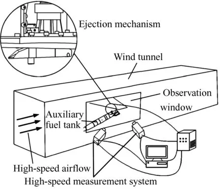
Fig.5 Measurement principle of the pose measurement method.
Fig.5 shows the principle of the pose measurement method.A high-speed measuring method based on white self-emitting units was designed to solve the problems caused by strong light reflection in measuring fuel tank models.With this method,the self-emitting units were firstly distributed at known spots on the surface of the model.Resins were then used to glue the holes which contained the self-emitting units to reduce effects to the aerodynamic shape of the model.Before dropping the model,a calibration method considering image distortions was employed to calibrate the cameras.Therefore,the internal and external parameters as well as the distortion coefficients of the cameras can be obtained.When performing the experiment,the auxiliary fuel tank was ejected when the free stream became steady.Meanwhile,the high-speed monodrome cameras were triggered to capture images of the released model with self-emitting units as recognizing targets.Constraints of spatial distances and extremities were employed to process the matching of targets in corresponding images from the two cameras.Finally,the 3D coordinates of the targets were reconstructed and pose information of the model was computed by coordinate conversion from those targets.
3.2.Image acquisition method for high-speed models
The complexity of wind tunnel environment has led to the following difficulties for the image acquisition method for high speed models.
(1)In order to meet the requirement of high-speed measurement,cameras with ultra-high speed frame frequency are employed to capture the image sequence of the model.However,the shortened exposure time caused by high speed frame frequencies will consequently affect the image brightness.Besides,in the dark environment of wind tunnels,image acquisition of models was even difficult due to the extremely low brightness.
(2)To avoid interference from the internal flow field of the wind tunnel,high-speed cameras and light source can only be arranged in a small space out of the observation window.Meanwhile,to ensure the accessibility of capturing the target motion,the two cameras should be installed at a slant angle against the observation window.Unfortunately,light would be easily reflected to cameras' lenses by the optical glass under such condition of installation,affecting the quality of image sequence.
(3)As is the case with the real auxiliary fuel tank,the scaled model is a small model with complex shape.However,in our experiment,components used to adjust the model's moment of inertia are installed inside the model.Thus,its inner space must be greatly narrowed.Therefore,reasonable installation and processing of markers on the model surface has become a barrier of image acquisition with the requirements of not affecting the aerodynamic shape of the model.
To solve those problems,colored self-emitting units were usually recommended to for image acquisition.15However,with the increasing shooting speed of cameras,the brightness of colored self-emitting units is too low to meet the requirement of image quality.Instead,we proposed a high-speed image acquisition method based on white self-emitting units.Differed from traditional reflective markers,the white self emitting units were stronger in brightness and stability,providing more high-brightness feature points for computer recognition.16Moreover,an external light source is no longer necessary for self-emitting markers,solving the problems of the low intensity of illuminations in the wind tunnel and light reflections between the external light source and the observation window.Another advantage of self-emitting units is small-sized.It is easy to install them on small scaled models.Power suppliers are miniature batteries wired inside the model body,avoid interaction of components inside the model.Using the proposed method,effects of the complex wind tunnel environment on the image acquisition were effectively reduced.And the quality of the image acquisition was improved.One of the images taken in the experiment is shown in Fig.6.
3.3.Automatic dynamic calibration
Camera calibration is required for quantitative image-based measurements to determine the camera interior and exterior orientation parameters,as well as the lens distortion parameters which supplement the collinearity equations.We employ a compound target consisting of a cross-shape target frame and a planar target for the cameras' calibration,which effectively solves the problems of the large space of wind tunnels and the high costs of traditional calibration targets.The compound target used in this paper is shown in Fig.7.Moreover,problems in traditional calibration involve the small number of features on the target,the lack of automaticity in calibration,and the long period of the calibration process,thus a dynamic calibration method is proposed in this paper.The compound target is placed in the measuring space and then moves all over the space as the cameras capture the real-time images of the target.Encoded markers are attached onto the cross-shape target frame,so that an automatic and high-speed recognition of the markers on the compound target can be realized,which effectively save the time for camera calibration.Besides,by moving the compound target all over the space,we are able to the increase the data for cameras' calibration and optimize the calibration precision as well,which helps to obtain more robust calibration results.
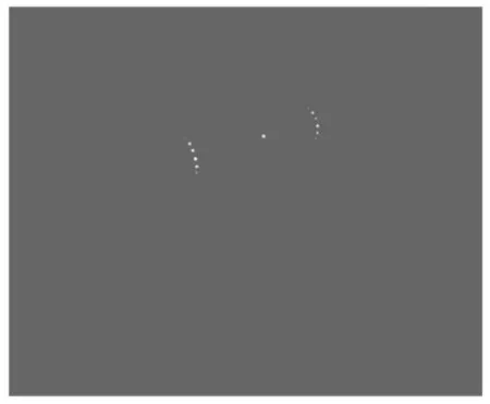
Fig.6 Image of self-emitting makers captured by high-speed image acquisition system.
The image and the world coordinate system are related through sequential rotational transformations,17that is

where(X,Y,Z)denotes the 3D coordinate of a particular point in the world coordinate system,(Xc,Yc,Zc)the coordinate of the perspective center in the world coordinate system,(x,y)the 2D coordinate of the corresponding point in the image plane,c the camera principal distance and(xp,yp)the photogrammetric principal-point location. δx and δy denote the shifts of the image point from its 'ideal' position on the image plane;λ is the scaling factor and the rotation matrices are defined as
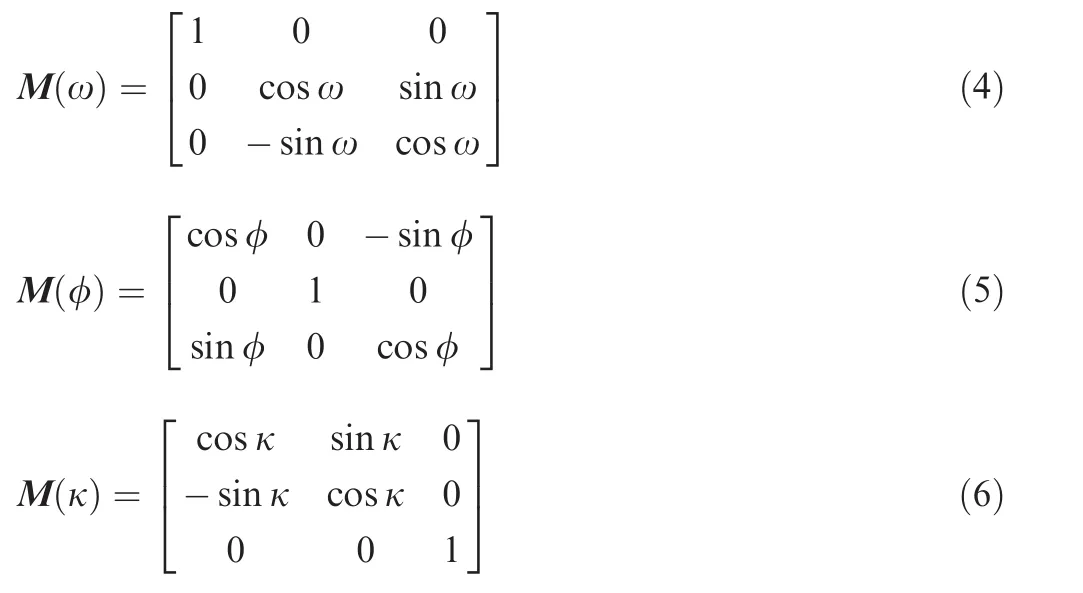
where ω,φ,and κ are the Euler orientation angles between the two coordinates.
The orientation angles(ω, φ, κ)are approximately the pitch,yaw and roll angles of a camera in an established coordinate system.The image coordinate shifts δx and δy can be modeled by a sum of the radial and decentering distortions18,19

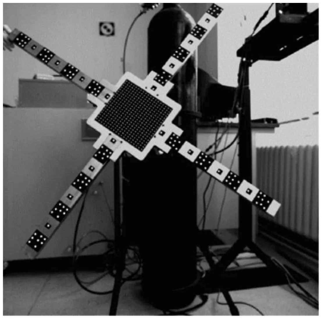
Fig.7 Compound target used for cameras' calibration.
where
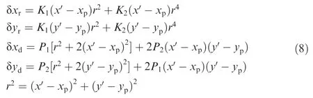
where K1and K2are the radial distortion parameters,P1and P2are the decentering distortion parameters,and x′and y′are the undistorted coordinates in the image plane.
3.4.Matching and division method for markers
The marker matching method here employs the distance constraint between markers to avoid mismatching.First,epipolar constraint of the image was used to conduct the marker matching.However,mismatching usually occurred when using the matching method based on limitation constraints.Thus the accuracy of pose measurement was affected.To avoid mismatching,relationship of distance constraints h1and h2between markers was firmly decided during machining so that markers' matching was conducted according to the constraints on distance between them to avoid mismatching(see Fig.8).In this case,the stability of the whole measurement system can be guaranteed.
The specific process of weeding out mismatch is as follows:(A)three groups of markers are placed at three sections of the model in circumferential direction with equal intervals in each group;(B)markers are initially matched using a limitconstraint method;(C)the 3D coordinates of markers are then reconstructed after the initial matching so that mismatched markers can be weeded out based on the fact that distances between the neighboring markers in the same group are fixed.
3.5.Measurement of pose parameters
The method of coordinate transformation was adopted in this paper.20Two coordinate systems-the initial reference coordinate system(IRCS)and local reference coordinate system(LRCS),were established.The IRCS and LRCS mean the reference coordinate systems were set up at the first frame and the frame of the measurement position,respectively.Then the position and attitude information of the models was computed through the coordinate transformation between the two coordinate systems(see Fig.9).The specific conversion relations are as follows

Fig.8 Specific layout of markers.
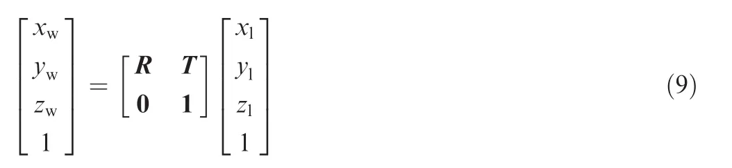
where T(the translation matrix)and R(the rotation matrix)depict the translation and rotation parameters of the model,respectively;(xl, yl, zl)denotes the coordinate of a particular point in the local coordinate system;(xw, yw, zw)is the coordinate of the corresponding point in the world coordinate system.The translation matrix T is written as

where xp,yp,zpare defined as the translation parameters of the model in x,y,z axis,respectively.The rotation matrixes of the new coordinate relative to the z,x and y axis are written as
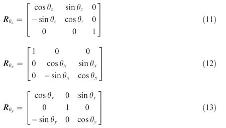
Thus the entire rotation matrix R can be written as

where θz,θx,θyrepresent the yaw angle,pitching angle and roll angle of the target,respectively.Finally,the position and attitude parameters can be computed according to the unity of the two coordinate systems.
4.Experimental process and results
4.1.Simulative separation system for external cargoes

Fig.9 Conversion relation between two coordinate systems.
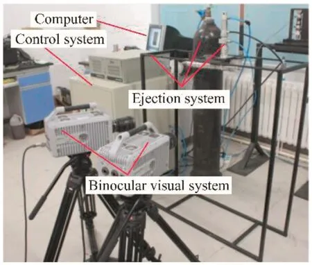
Fig.10 Simulative platform for separation experiments.
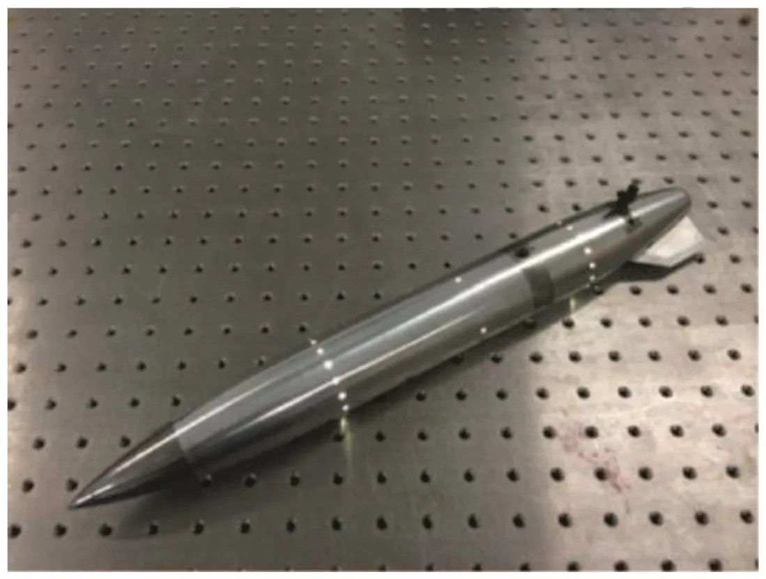
Fig.11 Scaled model of auxiliary fuel tank.
As shown in Fig.10,the simulative separation system for external stores we designed consists of an ejection mechanism,a control system,a pose measuring system and a computer processing terminal.Among those,the control system includes a pneumatic control system and a circuit control system.The pneumatic control system is responsible for store ejection,while the circuit control system energizes the rupture of the explosive bolt.When the simulative separation system finishes the release,an instantaneous image capturing process using the high-speed image acquisition system starts due to the signal from a proximity switch.Finally,the computer processing terminal achieves a fast and accurate measurement of pose parameters of the release model by analyzing the collected data.Fig.11 shows the scaled model for separation experiments.
4.2.Measurement experiments for auxiliary fuel tank models
Experiments were conducted in the laboratory which simulate the dark environment of wind tunnels using the measuring system mentioned in Section 4.1.The distance between the model plane and the cameras is 600 mm and the measuring field of view is 1000 mmX1000 mm.To finish the experiment,the cameras are firstly calibrated;the model is then ejected out of the mechanism by the controlling system which triggers the air cylinder and the explosive bolt.Simultaneously,the binocular vision system is triggered to capture the image sequence of the model and its pose parameters are obtained by analyzing those images.Fig.12 shows the results of position measurement and Fig.13,the results of attitude measurement.
It can be seen from the results that the model starts to be accelerated by the ejection mechanism 0.009 s after the cameras are triggered;and the release process finishes in 0.053 s,Fig.13 shows that the model's release angle is 12.5°,showing excellent performance of the system according to the practical requirement of the experiment.
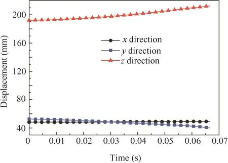
Fig.12 Results of position measurement.
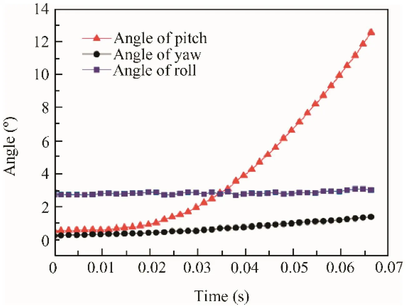
Fig.13 Results of attitude measurement.
4.3.Repeatability experiments for the system
The repeatability of a mechanism has a significant influence on the experimental results.On the one hand,the mechanism should guarantee a stable separation;on the other hand,repeatable results in many test runs are also required.Therefore,several experiments in the same condition were conducted in this paper.Moreover,the optical tracking method was used to test the repeatability of the store drop mechanism.The model was dropped 8 times to test the consistency of the ejection velocity and angular velocity,results of which are shown in Table 1.
It can be analyzed from Table 1 that the variance of the model's velocity and angular velocity the moment it ejects from the aircraft are 2 and 4.637,respectively,indicating excellent repeatability of the mechanism system.
4.4.Verification experiments
As shown in Fig.14,a highly accurate electronic platform has been employed to carry out the verification experiment.The scaled model was firstly mounted to the electronic platform through a special fixture.Then the electronic platform was controlled with designed translation(10 mm)and corner movement(5°)with high accuracy.Meanwhile,pose information of the model would be measured by the proposed measuring system.So the precision of the measuring system can becalculated through the comparison between the actual pose information of the electronic platform and the measured results.
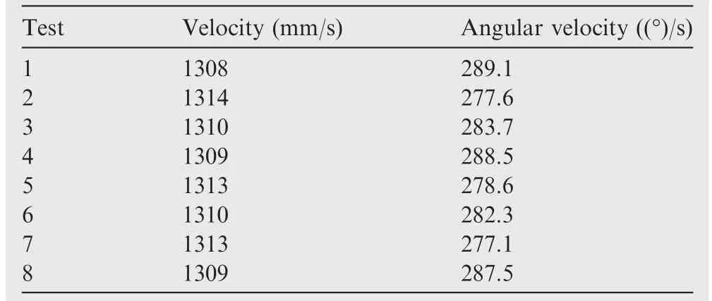
Table 1 Repeatability experiment of mechanism system.

Fig.14 Experimental setup for precision verification.
According to Table 2,the maximum deviation of displacement in x direction is 0.1 mm and the value in y direction is 0.12 mm;in z direction,it is 0.1 mm.Compared to the results of the measurement system based on color images,15the displacement precision of the measurement system is higher,owing to the high brightness of white self-emitting markers.
Results in Table 3 shows that the maximum deviation of the pitch angle is 0.1°,while that of the yaw angle is 0.12°,and the roll angle 0.34°.It can be noticed that the angular precision of the measurement system is higher compared to results of the measurement system based on color images,15thanks to the high brightness of white self-emitting markers.
5.Conclusion
(1)A simulative experimental system for external stores in wind tunnel environment has been presented in this paper.Through experiments,the system proves capable of achieving the release simulation and pose measurement for external stores.
(2)A simulative release mechanism has been designed so that the stable and controlled initial model velocity,angle and angularvelocity after ejection can beachieved.Besides,a scaled model of the original auxiliary fuel tank for experiments is designed and its moment of inertia is adjusted utilizing a vision system.

Table 2 Displacement precision of measurement system.

Table 3 Angular precision of measurement system.
(3)We propose a high-speed image acquisition scheme based on miniature self-emitting units,reducing the effects of the poor lighting condition,light reflection and high-speed movement of models.What's more,a binocular vision measurement system is established as well to measure the pose parameters of the model and results are of high accuracy.
(4)Several tests have been conducted in the laboratory to verify the repeatability of the measurement system,which indicates that the system meets the requirements of practical tests in wind tunnels.Future experiments will be conducted in real wind tunnel environment and improvements to the acquisition precision of markers would be studied.
Acknowledgements
This study was co-supported by the National Natural Science Foundation of China(Nos.51375075,51227004),the Special Funds of the National Natural Science Foundation of China(No.51227004),the National Basic Research Program of China(No.2014CB046504),the Fundamental Research Funds for the Central Universities of China,and the Science Fund for Creative Research Groups of China(No.51321004).
1.Zhou R,Huang XH,Zhang ZY,Li P.A captive trajectory system using double closed-loop velocity control.Acta Aeronaut Astronaut Sin 2014;35(6):1522–9[Chinese].
2.Johnson RA,Stanek MJ,Grove JE.Store separation trajectory deviations due to unsteady weapons bay aerodynamics.Reston:AIAA;2008.Report No.:AIAA-2008-0188.
3.Murray NE,Jansen BJ,Gui L.Measurements of store separation dynamics.Reston:AIAA;2009.Report No.:AIAA-2009-0105.
4.Scott Keen K,Morgret CH,Frank Langham T,Baker,Jr,WB.Trajectory simulations should match flight tests and other lessons learned in 30 years of store-separation analysis.Reston:AIAA;2009.Report No.:AIAA-2009-0099.
5.Guan DY,Cai WM.Spoiler's effect on the yawing attitude angle of the missile in the bay.Acta Aeronaut Astronaut Sin 2014;35(4):942–7[Chinese].
6.Burner AW.Model deformation measurements at NASA Langley Research Center.Proceedings of AGARD 81st fluid dynamics panel symposium on advanced aerodynamic measurement technology.Paris:AGARD;1997.
7.Burner AW,Liu TS.Videogrammetric model deformation measurement technique.Journal of Aircraft 2001;38(4):745–54.
8.Jones TW,Lunsford CB.Design and development of a real-time model attitude measurement system for hypersonic facilities.Reston:AIAA;2005.Report No.:AIAA-2005-1411.
9.Jones TW,Lunsford CB.A photogrammetric system for model attitude measurement in hypersonic wind tunnels.Reston:AIAA;2007.Report No.:AIAA-2007-1164.
10.Burner AW,Fleming GA,Hoppe JC.Comparison of three optical methods for measuring model deformation.Reston:AIAA;2008.Report No.:AIAA-2000-0835.
11.Watzlavick RL,Crowder JP,Wright FL.Comparison of model attitude systems:active target photogrammetry,precision accelerometer,and laser interferometer.Reston:AIAA;1996.Report No.:AIAA-1996-2252.
12.Martinez B,Bastide M,Wey P.Free flight measurement technique in shock tunnel.30th AIAA aerodynamic measurement technology and ground testing conference.Reston:AIAA;2014.p.16-20.
13.Jia ZY,Ma X,Liu W,Lu WB,Li X,Chen L,et al.Pose measurement method and experiments for high-speed rolling targets in a wind tunnel.Sensors 2014;14(12):23933–53.
14.Liu W,Zhang Y,Ma X.Measurement method for moment of inertia based on binocular vision.Chinese Journal of Scientific Instrument 2014;35(9):1972–8[Chinese].
15.Liu W,Shang ZL,Ma X.Position and attitude measuring method of auxiliary tank based on color-coding method in wind tunnel environment.Chin J Aeronaut 2015;28(4):1121–30[Chinese].
16.Liu W,Zhang Y,Shang ZL,Ma X.An image acquiring method for position and pose measurement of high-speed target in wind tunnel.Sensorsamp;Transducers journal 2013;160(12):635–44.
17.Liu TS,Burner AW,Jones TW,Barrows DA.Photogrammetric techniques for aerospace applications. Prog Aerosp Sci 2012;54:1–58.
18.Fraser CS.Photogrammetric camera component calibration-A review of analytical techniques.Washington,D.C.:International Society of Photogrammetryamp;Remote Sensing;1992.
19.Fryer JG.Camera calibration in non-topographic photogrammetry.In:Karara HM,editor.Non-topographic photogrammetry.2nd ed.Falls Church,VA:American Society for Photogrammetry and Remote Sensing;1989.p.59–69.
20.Liu SJ.Research on pose and position measurement method for high speed motion model dissertation.Dalian:Dalian University of Technology;2012.
Liu Weireceived his B.S.degree in 2001 from North China Electric Power University and Ph.D.degree in 2007 from Dalian University of Technology.Now he is an associate professor and Ph.D.supervisor at Dalian University of Technology.
22 May 2015;revised 22 July 2015;accepted 6 September 2015
Available online 9 May 2016
Aircraft auxiliary equipment;
Binocular vision;
Position and attitude measurement;
Release mechanism;
Simulation experiment
Ⓒ2016 Production and hosting by Elsevier Ltd.on behalf of Chinese Society of Aeronautics and Astronautics.This is an open access article under the CC BY-NC-ND license(http://creativecommons.org/licenses/by-nc-nd/4.0/).
*Corresponding author.Tel.:+86 411 84708159.
E-mail address:lw2007@dlut.edu.cn(W.Liu).
Peer review under responsibility of Editorial Committee of CJA.
杂志排行

CHINESE JOURNAL OF AERONAUTICS的其它文章
- Optimization on cooperative feed strategy for radial–axial ring rolling process of Inco718 alloy by RSM and FEM
- Measuring reliability under epistemic uncertainty:Review on non-probabilistic reliability metrics
- Optimum blade loading for a powered rotor in descent
- Experimental study of ice accretion effects on aerodynamic performance of an NACA 23012 airfoil
- Parachute dynamics and perturbation analysis of precision airdrop system
- Large-eddy simulation of shock-wave/turbulent boundary layer interaction with and without SparkJet control