Analysis of the Effect of the Equivalent Parallel Resistor of theComb Capacitive Accelerometer*
2016-11-08QUHaoPENGBeiZENGJianZHOUWuYUHuijun
QU Hao,PENG Bei,ZENG Jian,ZHOU Wu,YU Huijun
(Department of Mechatronics Engineering,University of Electronic Science and Technology of China,Chengdu 611731,China)
Analysis of the Effect of the Equivalent Parallel Resistor of theComb Capacitive Accelerometer*
QU Hao,PENG Bei*,ZENG Jian,ZHOU Wu,YU Huijun
(Department of Mechatronics Engineering,University of Electronic Science and Technology of China,Chengdu 611731,China)
Measurement of the sensing capacitance among the structure of the comb accelerometer could be affected by the equivalent electrical parameters besides the sensing capacitance.Equivalent electrical parameters of Multilayer Ceramic Capacitance(MLCC)have been studied,since the structure of the comb accelerometer is similar to Multilayer Ceramic Capacitance(MLCC),the equivalent electrical parameters of the comb accelerometer could be analyzed in the same way.This paper will introduce the model of the sensing capacitance with equivalent electrical parameters and analyzes the effect of these parameters on the measurement result.
MEMS;comb capacitive accelerometer;pspice circuit simulation;charge amplify circuit;equivalent parallel resistor
EEACC:7320E;7230doi:10.3969/j.issn.1004-1699.2016.10.003
MEMS capacitive sensor is widely used in navigation,measurement and other fields.Comb capacitive accelerometer is one typical MEMS capacitive sensor that transforms acceleration into capacitance and generates voltage signal[1].Measurement of sensing capacitance is an essential procedure for the capacitive accelerometer.Measurement result could be affected by the ambient temperature or the circuit parameters.The effect of temperature is discussed in[2-3].In this paper,the effect of the equivalent parallel resistor of the comb capacitive accelerometer will be discussed.Charge amplify circuit is widely used for its simple construction,high resolution and low power consumption[4-8].Basic schematic of the charge amplify circuit is shown in Fig.1.Cxis the unknown capacitance,Cfis the feed back capacitance.S1,S2and S3are switches and φ1,φ2are control signals[9].If there are other electrical parameters besides sensing capacitances connected to the input of the charge amplify circuit,measurement results might be affected.The sensing structure is similar to the Multilayer Ceramic Capacitance(MLCC),with the gaps between the electrodes are filled with dielectrics.Since the equivalent electrical parameters is commonly used in the model of MLCC,sensing structure of the accelerometer can be modeled as sensing capacitance with equivalent electrical parameters.The measurement result of the detecting system is determined by all electrical parameters of the sensing structure.This paper willintroduce the model of the sensing capacitance with equivalent electrical parameters and analyzes the effect of these parameters on the measurement result.
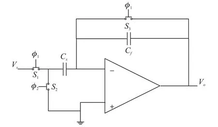
Fig.1 Basic schematic of the charge amplify circuit
1 Model of the Multilayer Ceramic Capacitance
The structure of Multilayer Ceramic Capacitance(MLCC)is shown in Fig.2.In the structure,Sn,Ni and Cu are the connect termination that connected to the circuit.The dielectric is ceramic and the electrodes are Pb[10-11].These parallel capacitances consist the total value of the ceramic capacitance.The equivalent circuit model of the MLCC is shown in Fig.3.

Fig.2 Circuit model of MLCC
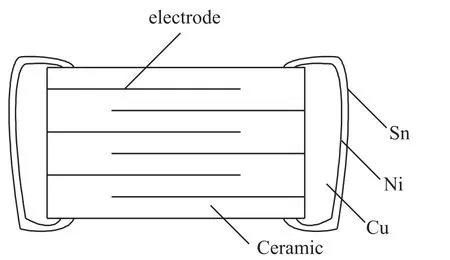
Fig.3 Structure of MLCC
Resis the equivalent series resistor,Lesis the equivalent series conductance,and Rdis the parallel resistror.The equivalent series resistor comes from the resistor of the electrode conductor material and is very small.Rdis result from the leakage current between different electrodes through the ceramic.Thus,Rdis very large.The total impedance of the capacitance is

According to Jeffrey Cain[12],ceramic capacitance has a Self-Resonant Frequency.When the circuit frequency equals to this frequency,Lesωs=1/(Cωs),the total impedance is Res.The ceramic capacitance degrades to a resistor.
The gaps between the electrodes of the accelerometer are filled with Nitrogen,besides sensing capacitance,Res,Lesand Rdmay also exist.However,the conductivity of the doped silicon is similar to conductor,and the Self-Resonant Frequency is larger than 1MHz,which is much higer than the circuit frequency of the charge amplify circuit,thus,Resand Lescan be ignored,only the parallel resistor should be considered.
2 The Sensing Structure Model with Parallel Resistors and Simulation Results
Sensing structure of the accelerometer is shown in Fig.4,and the equivalent circuit with parallel resistors is shown in Fig.5.
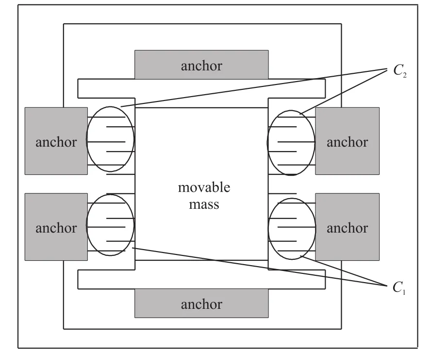
Fig.4 Sensing structure
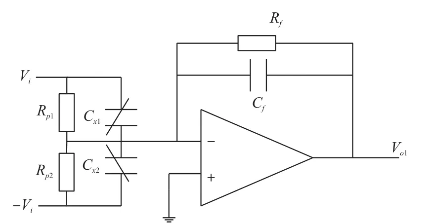
Fig.5 Equivalent circuit
Without the parallel resistors,output voltage is derived as:

When the parallel resistors are taken into consid-eration,the input impedance will change,denote the impedances XⅠ=1/(1/Rp1+jωCx1)=Rp1/(1+jωRp1Cx1),XⅡ= 1/(1/Rp2+jωCx2)=Rp2/(1+jωRp2Cx2),and let XⅢ=Rf/(1+ jωRfCf),we can derive the output voltage as:

From equation(3),we can see that if the parallel resistor Rp1and Rp2are very large,the second parts of equation(3)is near to zero,the effect of the parallel resistors can be ignored.The simulation is carried out with Pspice.Output voltages without and with parallel resistors are shown in Fig.6 and Fig.7.
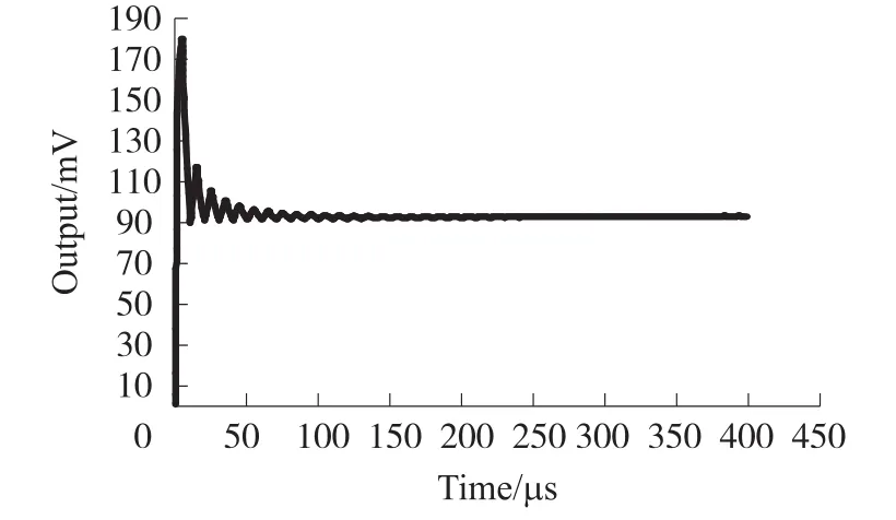
Fig.6 Output without parallel resistors
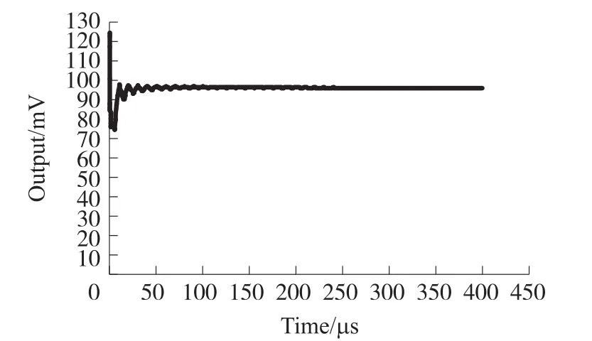
Fig.7 Output with parallel resistors
The simulation results show that stable outputs with and without parallel resistors are very close.
3 Conclusion
When the equivalent parallel resistor is introduced to the model of sensing capacitance,a new transform function of the detecting system is developed.From the new transform function of the detecting system,we can see that,if the equivalent parallel resistor is rather large,the measurement result will not be affected.
[1]Stephen B,Graham E,Michael K N W.MEMS Mechanical Sensors[M].Artech House,2004.
[2]He J,Xie J,He X,et al.Semi-Analytical M odel for Scale Factor Thermal Drift of Capacitive Microaccelerometers[J].Chinese Journal of Sensor and Actuators,2016,29(1):45-50.
[3]Zheng C,Chen J.Study of A Novel Method of Temperature Compensation for MEMS Accelerometer[J].Chinese Journal of Sensor and Actuators,2015,28(1):39-42.
[4]Arfah N,Zahirul Alam A H M,Khan S.Capacitance-to-voltage Converter for Capacitance Measuring System[C]//Mechatronics(ICOM),2011 4th International Conference on IEEE,2011:1-4.
[5]Zahirul Alam A H M,Arfah N,Sheroz K,Rafiqul I.Design of Capacitance to Voltage Converter for Capacitive Sensor Transducer[J].Journal of Applied Sciences on American,2010,7(10):1353-1357.
[6]Arfah N,Zahirul Alam A H M,Sheroz K.Design of Capacitive Measuring Systems for High Frequency Band Sensor Transducer[C]//2010 International Conference on Computer and Communication Engineering(ICCCE).IEEE,2010.
[7]Joost C Lötters,Wouter Olthuis,Peter H Veltink.A Sensitive Differential Capacitance to Voltage Converter for Sensor Applications[J].IEEE Transactions on Instrumentation and Measurement,1999,48(1):89-96.
[8]Huang S M,Stott A L,Green R G,et al.Electronic Transducers for Industrial Measurement of Low Value Capacitances[J].Journal of Physics E Scientific Instruments,2000,21(3):242-250.
[9]Stephen D.Senturia,Microsystem Design[M].New York:,2001.
[10]Kim M G,Lee B H,Yun T Y.Equivalent-Circuit Model for High-Capacitance MLCC Based on Transmission-Line Theory[J].IEEE Transactions on Components Packaging&Manufacturing Technology,2012,2(6):1012-1020.
[11]Du S.Equivalent-Circuit Modeling for Multilayer Capacitors Based on Coupled Transmission Line Theory[J].IEEE Transactions on Components Packaging&Manufacturing Technology,2011,1(5):731-741.
[12]Cain B J,Parasitic Inductance of Multilayer Ceramic Capacitors[R].AVX corporation.

曲昊(1988-),男,博士研究生,2011年获得电子科技大学学士学位,2011年起攻读电子科技大学硕士学位,2013年起攻读电子科技大学博士学位,主要从事MEMS惯性器件检测电路设计,微小电容检测电路设计与测试方面的研究,708382@163.com;

彭倍(1977-)男,教授,博士生导师,1999年获得北京航空航天大学学士学位,2008年获得美国西北大学博士学位,主要从事薄膜特性,MEMS/NEMS材料特性等方面的研究,beipeng@uestc.edu.cn。
梳齿式电容加速度传感器等效并联电阻对器件输出产生的影响*
曲昊,彭倍*,曾建,周吴,于慧君
(电子科技大学机械电子工程学院,成都611731)
梳齿式电容加速度传感器检测电容的测量结果会受到除感应电容之外的其他等效电路参数的影响。梳齿式电容加速度传感器的结构与多层瓷片电容(MLCC)的结构类似,因此可以借鉴多层瓷片电容中等效电路参数的研究方法对电容加速度传感器中的等效电路参数进行研究。本文将对梳齿式电容加速度传感器检测结构中的等效电路参数进行建模,并分析这些等效电路参数对测试结果产生的影响。
MEMS;梳齿式电容加速度传感器;Pspice电路仿真;电荷放大电路;等效并联电阻
TH824.4
A
1004-1699(2016)10-1483-03
2016-04-28修改日期:2016-06-08
项目来源:This work was supported in part by NSAF(U1530132);National Natural Science Foundation of China(51505068,51575090)
