Mixing of two different electrolyte solutions in electromagnetic rectangular mixers*
2016-09-29MeimeiWENChangNyungKIMYueYAN
Meimei WEN,Chang Nyung KIM, Yue YAN
Mixing of two different electrolyte solutions in electromagnetic rectangular mixers*
Meimei WEN1,Chang Nyung KIM2, Yue YAN1
1. Department of Mechanical Engineering, Graduate School, Kyung Hee University, Yongin, Korea, E-mail: 402233603@qq.com 2. Department of Mechanical Engineering, College of Engineering, Kyung Hee University, Yongin, Korea (Received January 14, 2015, Revised April 24, 2015)
This study proposes a new electromagnetic rectangular mixer, and numerically examines the mixing characteristics of two different electrolyte solutions in the device under a uniform magnetic field. The mixer consists of a conduit with electrodes equipped on its top and bottom walls. The difference in the electric potentials applied to the sets of electrodes induces the current. The combi- nation of the induced current and magnetic field yields Lorentz force, resulting in the fluid motion for pumping and mixing of the two different fluids. The numerical simulation is carried out with the use of commercial software CFX. The present numerical model is validated by an existing numerical work. The effect of different variables on mixing efficiency is investigated in many different cases with two different heights of the duct and various input voltages of the electrodes. The current simulation results indicate that the mixing performance can be enhanced by using multiple sets of electrodes and applying higher input voltages (absolute values) to the electrodes.
CFX, electrolyte solution, Lorentz force, mixer, mixing efficiency
Introduction
In recent years, there has been a growing interest in microfluidic devices, which are widely used in bio- detection, biotechnology, chemical reactors, medical and environmental monitors. In order to facilitate che- mical and biological reactions, the mixing and pumpi- ng of various reagents and chemicals are often nece- ssary. Since the characteristic length of microdevices is usually very small, the effective mixing is too slow to be achieved with low diffusivity. Meanwhile, the Reynolds number of liquid flows in such micro-cha- nnels is usually very small, thus turbulence that may enhance mixing is not available[1]. Therefore, more ef- ficient microdevice is required for higher mixing effi- ciency.
Generally speaking, microfluidic mixers can be categorized as passive or active micromixers. The pa- ssive microfluidic mixers perform the mixing by in- creasing the contact area and contact time of the mi- xing species[2]. Many investigators have performed various researches on passive microfluidic mixers. For example, Buchegger et al.[3]presented a multi-lamina- tion micromixer with four wedge-shaped inlet channe- ls for fast and highly uniform fluid mixing in the low- millisecond range. The four-layer laminar flow was created by a fluidic distribution network. Due to the optimized wedge-shaped inlet channels, this micro- mixer could be applicable in a situation with very low flow rate and could reduce reagent consumption. Liu et al.[4]fabricated a three-dimensional serpentine mi- crochannel with a “C-shaped” repeating unit in silicon wafer, where the mixing was enhanced passively by implementing chaotic advection. Yi and Bau[5]desi- gned a two-dimensional serpentine conduit in low- temperature co-fired ceramic tapes. They took advan- tage of bend-induced vortices to stir the fluids and en- hance the mixing process. Wang and Lin[6]constru- cted a passive chaotic micromixer with helical micro- channels, which achieved higher mixing efficiency compared to those of straight and serpentine micro- channels when Reynolds number was low. Wang et al.[7]numerically investigated the electromagnetic fea- tures and mixing performance of diffusing species in the passive micromixer embedded with barriers. They found that the specially embedded periodic barriers could shift the flow pattern and produce blinking flow, which could facilitate the mixing process.
The active microfluidic mixers enhance the mi- xing performance by applying some external forces to accelerate the transport process[8]. Typically, active mixers use acoustic (or ultrasonic), dielectrophoretic, electrokinetic time-pulse, pressure perturbation, ele- ctro-hydrodynamic, magnetic and thermal techni- ques[2]. The magneto-hydrodynamic (MHD) effect has been used by many researchers to realize active mi- cromixers. For example, Bau et al.[9]designed an acti- ve micromixer equipped with arrays of electrodes on the conduit's bottom wall. By applying alternating po- tential differences across the pairs of electrodes, the current was induced. In the presence of a magnetic field, the combination of the current and magnetic field induced Lorentz force, which could be used for mixing. Yi et al.[10]developed a micromixer which consisted of a circular cavity. An electrode (denoted by C) was deposited on the side wall of the cavity, and two copper-wire electrodes (denoted by A and B) were placed eccentrically inside the cavity. By alter- nately activating two pairs of electrodes AC and BC over a period, the complicated fluid motions could be generated. In addition, the complexity of the motion increased with the increasing of the alternation period. La et al.[11]designed an MHD mixer, in which a pair of electrodes (for pumping) were positioned on the side walls and many pairs (for mixing) on the bottom wall repeatedly. The Lorentz force, a driving force for the flow, could be variously induced in the micro- channel by changing the applied voltages of the ele- ctrodes. Three-dimensional CFD simulations under steady-state condition were carried out to examine the mixing performance of the device.
The Lorentz force can be used not only for mi- xing, but also for pumping. In previous studies about microfluidic systems, Jang and Lee[12]presented a mi- cropump where pumping mechanism was based upon MHD principles. Lorentz force was used as the pum- ping source of the micropump. The performance of the micropump was obtained by measuring the pressu- re head difference and flow rate with different volta- ges. Lemoff and Lee[13]constructed an AC MHD mi- cropump in which the Lorentz force was used to pro- pel the electrolyte solutions. The micropump produced a continuous (not pulsatile) flow and was compatible with solutions containing biological specimens. Their results demonstrated that multiple, independently-con- trolled pumps could be integrated on a single chip th- rough the design of the AC MHD micropump. Zhong et al.[14]fabricated a micropump with co-fired ceramic tapes at low temperature. The shape of the conduit in the device was of a toroidal loop with the rectangular cross-section. They showed that the Lorentz force could be utilized to propel liquids such as saline solu- tion and deionized water in minute conduits. Bau et al.[15]presented the feasibility of the use of Lorentz force to control fluid flow in microfluidic networks. By prescribing either the potential or the current acro- ss electrode pairs, the liquid flow could be controlled in a programmable way, without the need for mecha- nical pumps or stirrers.
In view of the above-mentioned previous works, several studies[9-11]have been performed for MHD mi- xers, but numerical works on MHD mixers have rarely been conducted. Bau et al.[9]presented the theoretical and experimental investigation of the electrolyte solu- tions in a rectangular MHD micromixer. Here, the ele- ctrodes positioned on the bottom wall of the micro- channel can be used for mixing only. But, in the pre- sent study, the electrodes positioned on the top and bottom walls of the microchannel can be used for si- multaneous mixing and pumping, thus the time for well mixing can be shortened. A two-dimensional, time-periodic flow of saline solutions in a circular MHD mixer is theoretically and experimentally stu- died by Yi et al.[10], while a three-dimensional, steady- state, incompressible, constant-property, laminar flow of electrolyte solutions in a rectangular MHD mixer is numerically considered in this study. In the works of Bau et al.[9]and Yi et al.[10], the mixers have the fun- ction of mixing only. Though the microdevice in La’s work[11]can serve both as a pump and a mixer, a pair of side-walled electrodes for pumping and many pairs of bottom-walled electrodes for mixing are used.
In the present study, a new electromagnetic recta- ngular mixer for electrolyte solutions with pumping function is proposed. An arrangement of electrodes quite different from those of Refs.[9-11] is devised, so that an electrode can be used for generating the curre- nt flow for simultaneous pumping and mixing. By applying different electric potentials to different ele- ctrodes, the Lorentz force with different intensity is generated, which induces the fluid motion. In the pre- sent work, many different cases with two different heights of the duct and various electrode voltages are numerically investigated for the comparison of the mi- xing performance, which are rarely studied in Refs.[9- 11]. The detailed information of current density, velo- city distribution, and mass fraction of one fluid, toge- ther with the value of mixing index, is obtained.
1. Problem formulation
1.1
In the current study, the flow fields with one set,two sets, three sets and four sets of electrodes are in- vestigated. Since the duct geometries with three and four electrode sets are similar to that of two electrode sets, the geometries of the duct with three and four electrode sets are not to be displayed. The duct geo- metries with one set and two sets of electrodes are de- picted in Fig.1. Two different electrolyte solutions are denoted by Fluid A and Fluid B, respectively. In Fig.1(a), eight electrodes are positioned on the walls of the conduit as one set. Four electrodes are on the top wall, denoted by,,and, respe- ctively, the other four are on the bottom wall, denoted by,,,, respectively. The size of each electrode is 1 mm×1 mm. The distancebetween any two adjacent electrodes in one set (i.e., the dista- nce betweenandin Fig.1(a)) is 1 mm. Figure 1(b) shows the duct geometry in a situation with two sets of electrodes, and the distance between the two different electrode sets (i.e., the distance be- tween the first and second set) is 8 mm.
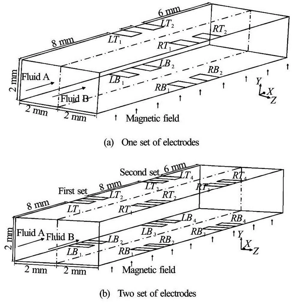
Fig.1 Duct geometries for different number of the electrode sets, and the coordinate system (These geometries are for Case 1)
Two cases (Case 1 and Case 2) with different as- pect ratios of the cross-section are considered in this study to investigate the mixing performance. Figure 2 shows the schematic of the cross-sections in the two cases, wheremeans the height of the conduit. Here, the aspect ratio is 2 in Case 1 (width of 4 mm, height of 2 mm), and is 1 in Case 2 (width of 4 mm, height of 4 mm), respectively. In each of Case 1 and Case 2, three subcases with different combinations of input voltage of the electrodes are considered, as shown in Table 1. The situations with different number of the electrode set (one-set, two-sets, three-sets and four- sets) are investigated in each subcase. A uniform mag- netic field (0.2 Tesla) is applied in thedirection in all cases.
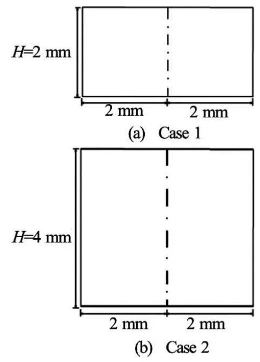
Fig.2 Schematic of the cross-sections in Case 1 and Case 2

Table 1 Input voltages of the electrodes in different cases (V)
By applying different potentials to different ele- ctrodes, current can be induced. The combination of the induced current and magnetic field yields Lorentz force, creating the fluid motion for pumping and mi- xing, dispensing with the need of mechanical pumps or stirrers. Figure 3 presents the schematic diagrams of the induced current and the corresponding Lorentz force in the fluid region near the top wall. As can be seen in Fig.3(a), the currentflows fromto, and fromto, which induces thedi- rectional Lorentz forceused for mixing. In Fig.3(b), the currentis in the negativedire- ction, which yields thedirectional Lorentz forceused for pumping. The combination of thedi- rectional Lorentz force and thedirectional Lorentz force yields the simultaneous mixing and pumping of the fluids. Also, the current can flow fromto. And, with the combination of this current anddire- ctional magnetic field, the Lorentz force havingdi- rectional anddirectional components is induced. Thedirectional component of Lorentz force can enhance the mixing effect, while thedirectional component of Lorentz force can enhance the pumping effect, just as shown in Fig.3(a) and Fig.3(b). Ifis large, the mixing performance of the fluids will be st- rong, ifis strong, the effect of pumping will be strong, which may force the fluids to move fast in the main flow direction, and may not allow the flow to have enough time for mixing. Therefore, the magnitu- de of the two forces should be well allocated. The ar- rangement of the electrodes on the bottom wall is the same as that on the top wall (see Fig.3), so that the fluid motion observed in the fluid region near the top wall can be seen in the fluid region near the bottom wall.
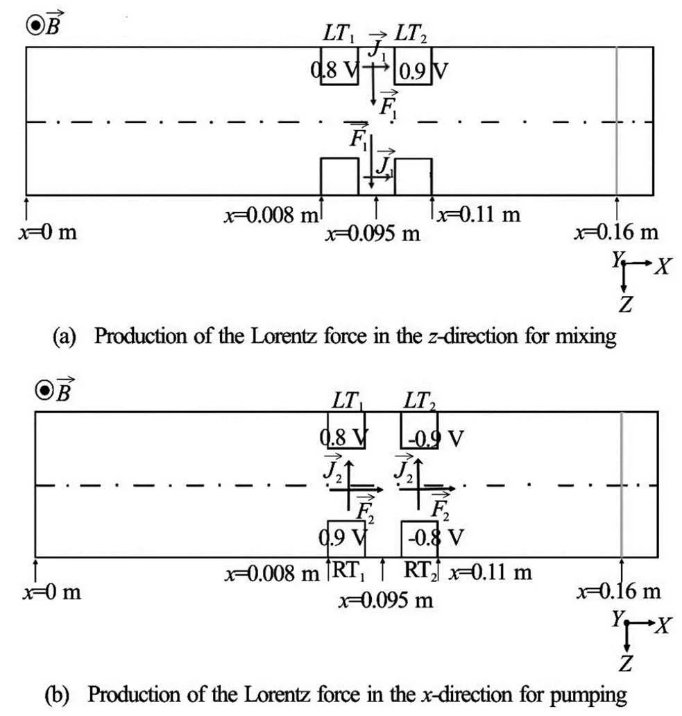
Fig.3 Schematic diagrams of the induced current , the co- rresponding Lorentz force in fluid region near the top and bottom walls in the situation with one set of ele- ctrodes, and illustration of the position (grey) for displa- ying the mixing performance
Phosphate buffered solution (abbreviated PBS) is a water-based salt solution, which contains sodium phosphate, potassium chloride and potassium pho- sphate. It is commonly used as the medium for the fi- xation of protein in biological research. In this study, PBS is chosen as the working fluid of the proposed microdevice, whose properties are given in Table 2.

Table 2 Properties of PBS solution
1.2
A steady-state, incompressible, constant-property, laminar flow of an electrically conducting fluid under a uniform magnetic field is considered. To consider the MHD effect, the continuity equation for fluid, equation of motion, continuity equation for electric charge, and Ohm’s law are applied. The system of go- verning equations can be written as follows:
Conservation of mass
Equation of motion
Conservation of the charge
Ohm’s law
Substituting Eq.(4) into Eq.(3) gives the followi- ng equation for the electric potential, where the ele- ctrical potential has an elliptic behavior with a source term of the electromotive forces
Equations (1), (2) and (5) are to be solved for velocity, pressure, and electric potential of the flow. The con- centration distribution inside the whole duct can be described by the following convective-diffusion equa- tion
1.3
No slip condition is applied at the liquid-wall in- terface. At the inlet and outlet of the duct, the pressure is prescribed to be zero, and the variables (except for the pressure) do not change in the main flow direction. It is considered that there is no normal current at the inlet, outlet, and liquid-wall interface (except at the electrodes), yielding the insulating boundary condition for the electricity, whereis the unit ve- ctor outer normal to the side wall.
The boundary condition for the concentrationsat the side wall is, which follows from the assumption that the wall boundary prohibits the diffusion in the fluids. In this study, two kinds of electrolyte solutions are referred to as Fluid A and Fluid B, whose concentrations before entering the inlet are 1 and 0, respectively.
1.4
Four important dimensionless parameters in fluid mechanics (Reynolds number, Hartmann number, Peclet number and magnetic Reynolds number) are in- troduced to characterize the flow in the system.
The Peclet number for mass transferis the ratio of the characteristic time of diffusive effect to the characteristic time of inertial effect, which is calcula- ted by
In this study, the value of binary diffusion coeffi- cient is[16]. Thus, the typical value ofis around 104, underlining that the typical diffu- sion time scale is much larger than the convective time scale. As a consequence, the convective transport dominates diffusive transport when the Peclet number is large, and the dispersion of the fluids in the flow field can be greatly enhanced by effectively promoting the convective transport. Therefore, a new micromixer is designed to enhance the convection in order to im- prove the mixing in the present study.
The magnetic Reynolds numbergives an estimate of the effect of magnetic advection to magne- tic diffusion, which is typically defined by
1.5
After a series of grid independence tests, a stru- ctured grid system is chosen in the present study. In the current simulation, the number of grids for the flow fields with one set, two sets, three sets and four sets of electrodes in Case 1 is around 17 000, 28 000, 39 000 and 50 000, respectively. In Case 2, the num- ber of grids for the flow fields with one set, two sets, three sets and four sets of electrodes is around 34 000, 56 000, 78 000 and 100 000, respectively. The Multi- grid-accelerated Incomplete Lower Upper Factoriza- tion technique[17,18]is used to solve the discretized equations. For the solution method of coupled gove- rning equations, under-relaxation is utilized in the ite- ration procedure. The second-order upwind scheme is used to discretize the convection terms and the central difference scheme is used for the diffusion terms.
2. Validation
Numerical simulations of three types of MHD flows generated in a micro-channel for pumping and/ or mixing are carried out to validate the accuracy and reliability of the present numerical model by the nu- merical results of La[11]In the study of La[11], PBS so- lution is used as the working fluid. Figure 4(a) shows the duct geometry, where the magnetic field is applied in thedirection with the intensity of 18.7 mT. A pair of electrodes (for pumping) are positioned on the two side walls and many pairs of electrodes (for mi- xing) are arranged periodically on the bottom wall. The voltage imposed on the side-walled electrodes are denoted byand. On the bottom wall, the vol- tages ofandare periodically applied on the electrodes. By changing the applied-voltage conditio-ns of the patterned electrodes (,,and) inside the microchannel, the Lorentz force can be in- duced in various directions and magnitudes. Three di- fferent types of MHD flows (axial, sinusoidal, and multi-vortical flows) created by the above-mentioned Lorentz force are discussed. The applied voltage con- ditions for the three types of the MHD flow conside- red in La’s simulations[11]are as follows: Firstly, for the axial flow (for pumping only), the voltages applied to the electrodes areV,V and there is no current betweenand(that is,). Secondly, for the sinusoidal flow (for pumping and mixing), the voltages applied to the ele- ctrodes areand. Thirdly, for the multi-vortical flow (for pumping and mixing), the voltages applied to the electrodes are,and.
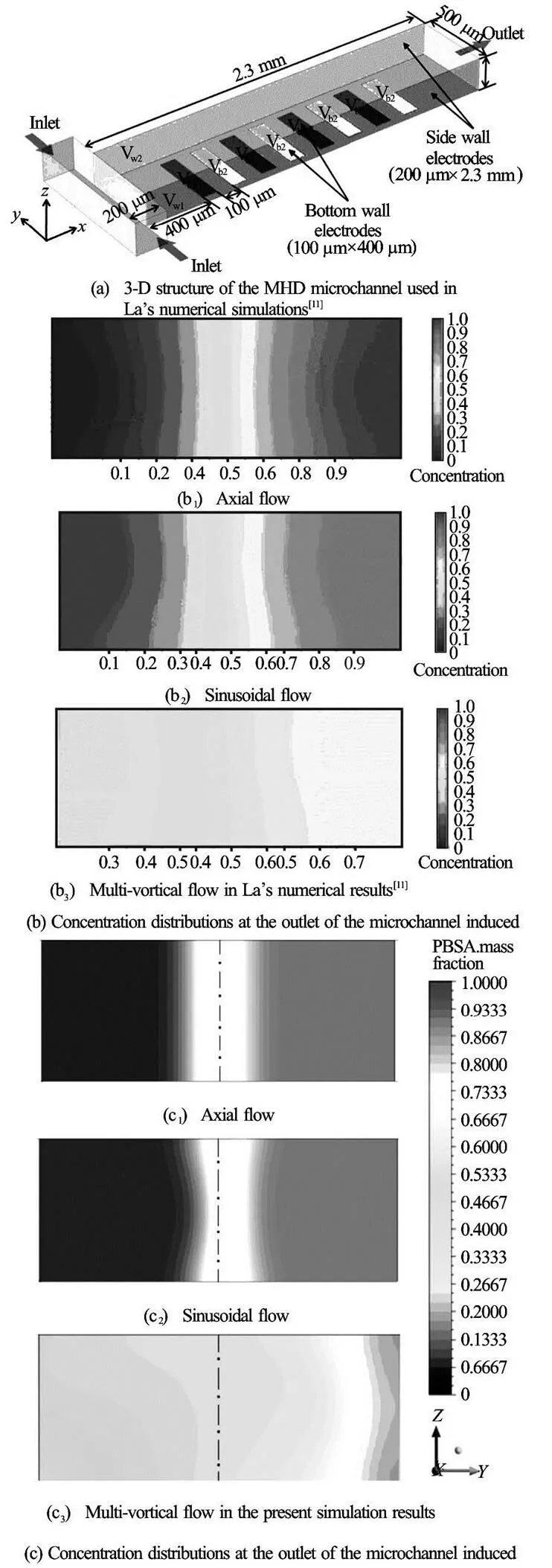
Fig.4 Validation of the present numerical model
The comparison of the concentration distribution at the exit of the microchannel between La’s numeri- cal results[11]and the present simulation results for (b1), (c1) axial flow, (b2), (c2) sinusoidal flow, and (b3), (c3) multi-vortical flow are shown in Figs.4(b) and 4(c), respectively, which demonstrates a good agreement. The standard deviations of the cross-sectional concen- tration values for the cases of the axial, sinusoidal, and multi-voritcal flows in La’s numerical results are re- ported to be 0.343, 0.293, and 0.096, respectively. Meanwhile, these values in the present simulation re- sults are 0.367, 0.312, and 0.098, respectively. The di- fferences in the standard deviation between La’s nu- merical results and the present simulation results are 6.9%, 6.5% and 2.1%, respectively. With smaller di- fferences shown above, the present numerical model is validated.
3. Results and discussions
3.1
Figure 5 shows the three-dimensional velocity st- reamlines in the situation with one set of electrodes in Case 1-1 (,). In Fig.5, the fluids are sucked at the inlet, then form one clockwise circu- lation in the region nearby,,and, and another counter-clockwise circulation in the re- gion nearby,,and, and finally, flow out at the outlet. Figure 6(a) depicts the distribu- tion of the electric potential in the midplanein the situation with one electrode set in Case 1-1. Note that the boundary condition for the ele- ctric potential is such that the walls, inlet and outlet are electrically insulated. The electric potential in the fluid region near,is higher than that near,, causing the current to flow fromto, and fromtoapproximately in thedirection, as depicted in Fig.6(b). Thus, thedire- ctional Lorentz force is induced in the region near,,and, driving the fluids to flow in thedirection, which can be seen in Fig.6(c). Figure 6(d) presents the plane velocity in the midplane, where a clockwise fluid circulation (near,) and an anticlockwise fluid circulation (near,) are observed, which are induced by the Lorentz force. Figure 6(e) shows the pressure distribu- tion in the midplane, where higher pressure is witnessed in the fluid region nearand. The Lorentz force, which generates the fluid flow shown in Fig. 6(d), is, in part, balanced by the pressure force.
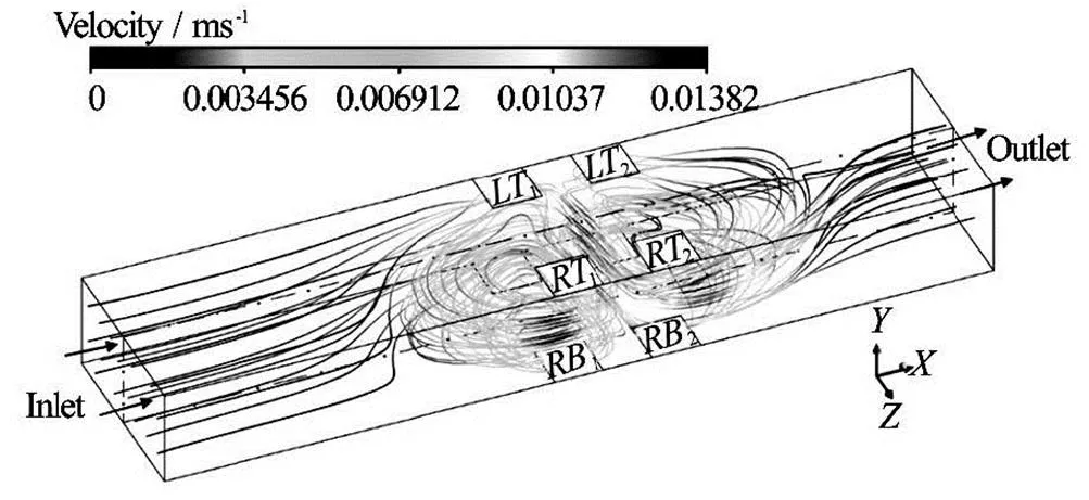
Fig.5 Three-dimensional streamlines of the velocity in the si- tuation with one set of electrodes in Case 1-1 ( 2 mm)
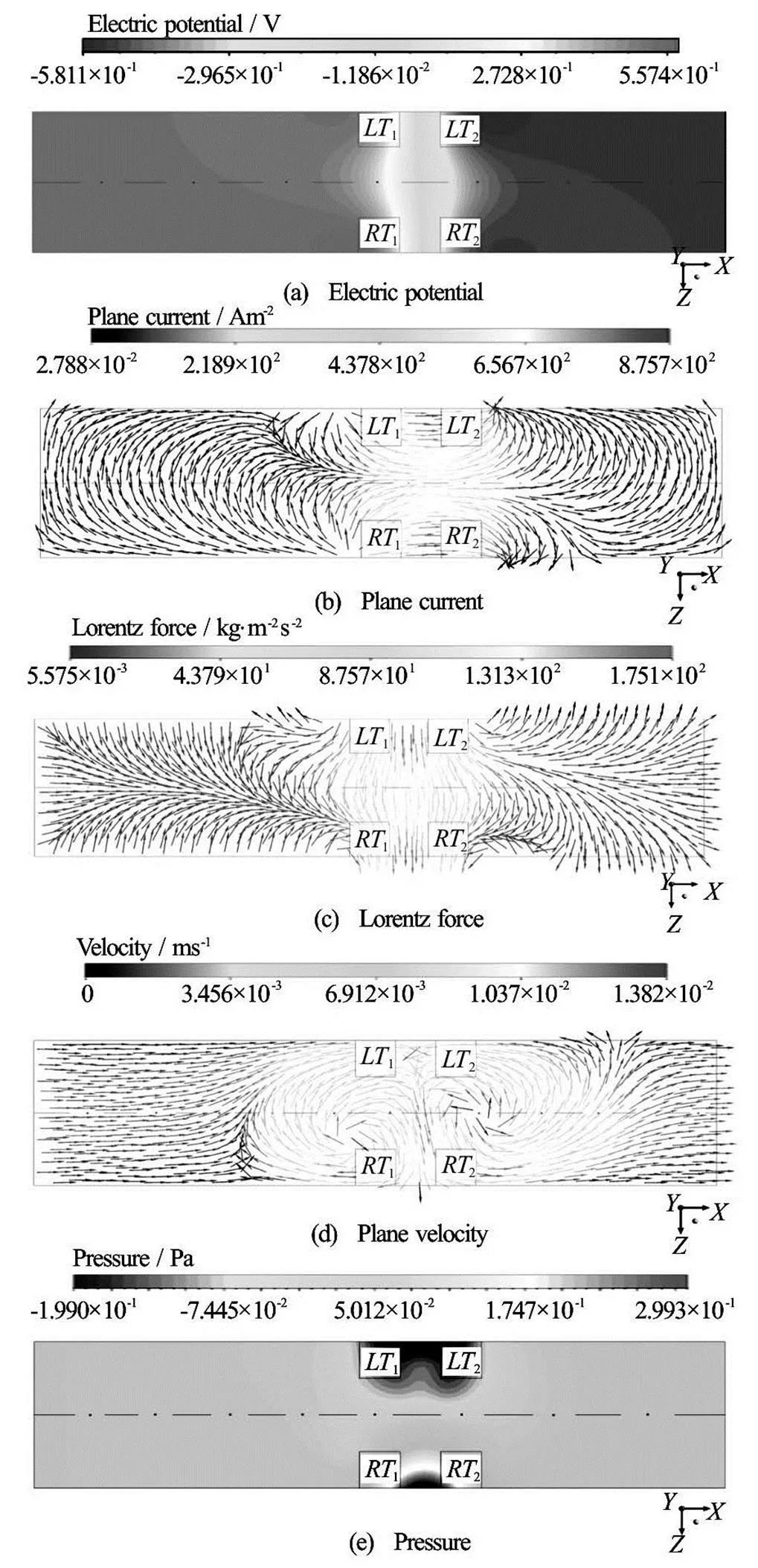
Fig.6 Distributions of electric potential, plane current, Lorentz force, plane velocity and pressure in the mid plane () in the situation with one set of electrodes in Case 1-1
Figure 7(a) shows the distribution of the axial cu- rrent at(see Fig.3) in the situation with one set of electrodes in Case 1-1. Thedirectional component of current in the plane induces thedire- ctional Lorentz force shown in Fig.7(b), generatingdirectional velocity displayed in Fig.7(c), which is used for mixing. Figure 7(d) depicts the pressure dis- tribution in the same plane, and higher pressure is ob- served near the right vertical wall (parallel to thedirection).
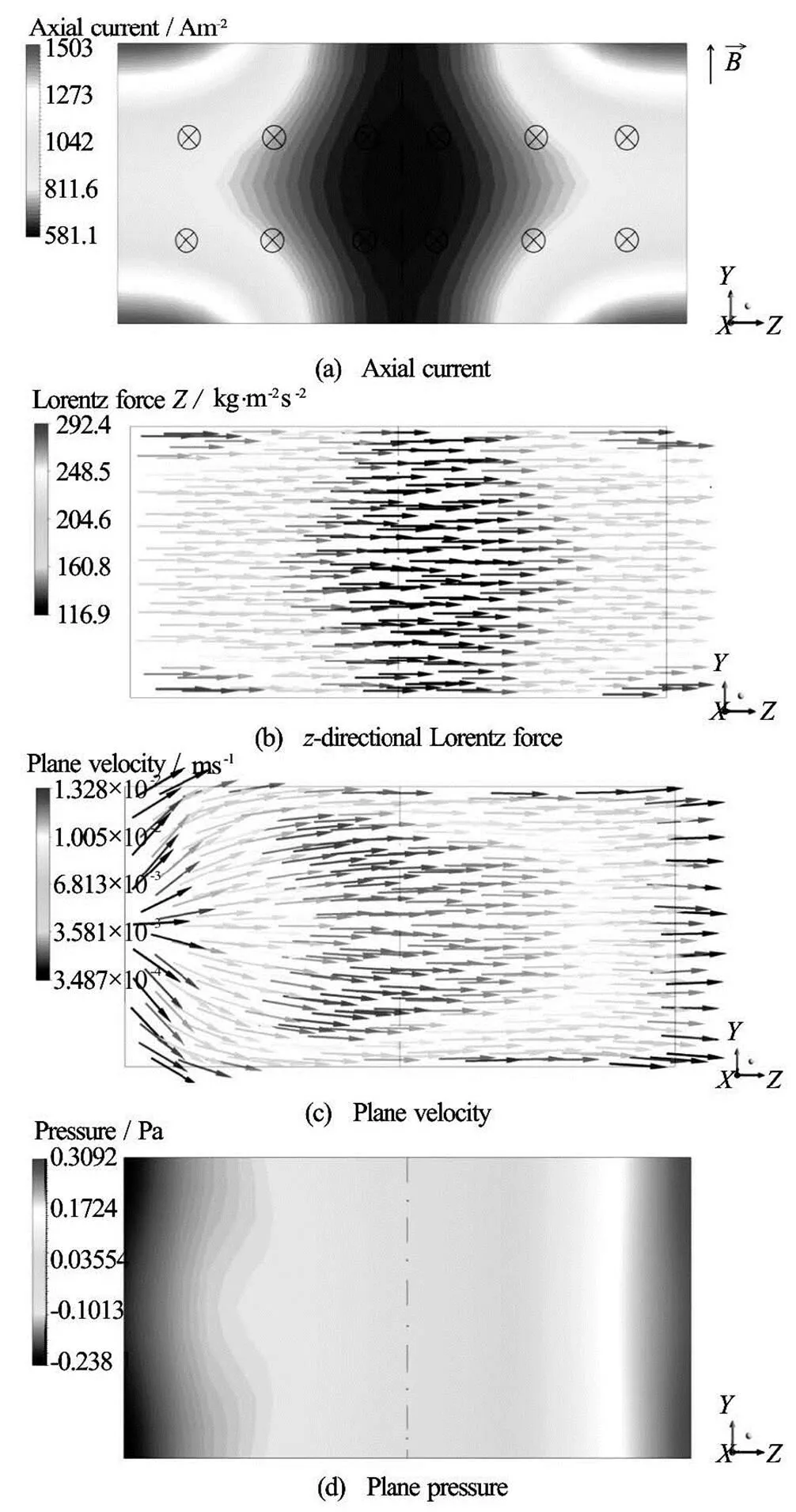
Fig.7 Distributions of axial current, directional Lorentz force, plane velocity and plane pressure at 0.0095 m in the situation with one set of electrodes in Case 1-1 , where means the positive dire- ction, means the negative direction
Figure 8(a) presents the plane current distribution at(see Fig.3) in the situation with one electrode set in Case 1-1, where the plane current flows almost in the negativedirection. Since the magnetic field is applied in thedirection, thedirectional component of Lorentz force depicted in Fig.8(b) is induced, which can be used for pumping. It is noted that the Lorentz force in the central fluid re- gion of the plane is much stronger in association with higher current density, than that in the fluid region near the walls parallel to the magnetic field (see Fig.8(b)). It is found that in Fig.6(d) the point of fluid reattachment is located at, and in Fig.6(e) the highest pressure in the bottom wall (para- llel to the magnetic field) is observed at0.0096 m. Thus, at, the axial velocity induced in the fluid region near the right vertical wall (parallel to thedirection) has a direction opposite to the main flow, as shown in Fig.8(c).
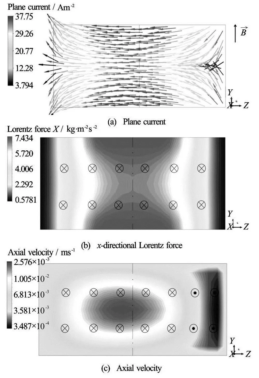
Fig.8 Distributions of plane current, directional Lorentz force and axial velocity at in the situa- tion with one set of electrodes in Case 1-1 (2 mm)
3.2
In this section, the effect of height of the duct on the mixing performance is to be considered. The hei- ght of the duct is 4 mm in Case 2, which is larger than that in Case 1. Since the fluid motion in Case 2 is similar to that of Case 1, the detailed descri- ption of the velocity in Case 2 is not displayed. With an increase in the height of the conduit, the current density decreases. Figure 9 depicts the current density distributions atfor the flow field with one electrode set in Case 1-1and in Case 2-1. In both cases, thedirectional components of current near the top and bottom walls are much higher, yielding strongerdirectional Lorentz forces (for mixing) therein, as shown in Fig.10. It can be obviously seen that thedirectional current atin Case 1-1 (see Fig.9(a)) is much higher than that of Case 2-1 (see Fig.9(b)). The- refore, the correspondingdirectional Lorentz force in the same plane in Case 1-1 (see Fig.10(a)) is stro- nger, resulting in better mixing performance.
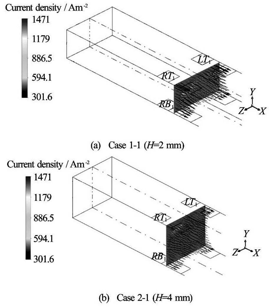
Fig.9 Distributions of the current density in the plane at 0.0095 m in the situation with one set of electrodes in Case 1-1 and Case 2-1 , where means the height of the conduit

Fig.10 Distributions of the Lorentz force at in the situation with one set of electrodes in Case 1-1 and Case 2-1
3.3
Two kinds of electrolyte solutions in the present study are referred to as Fluid A and Fluid B, whose concentrations before entering the inlet are 1 and 0, respectively. If the mixing result is perfect, the con- centration of the fluids after the mixing process will be 0.5. The concentrations of the flow field in differe- nt cases are investigated. Figure 11 shows the concen- trations in the situation with one set of electrodes in Case 1-1 and Case 2-1. Near the inlet, the two fluids are not practically mixed, so the concentration in the part of Fluid A is 1 and that in the part of Fluid B is 0. In the fluid region near the electrode set, the two flui- ds are somewhat mixed, as depicted in Fig.11. Here, the concentration at the outlet is nearly 0.5, showing that the mixing efficiency is high. Meanwhile, the cross-section for the mass-fraction (concentration) dis- play is chosen to be located 5 mm downstream from the trailing edge of the latest electrode (that is0.016 m, for the flow field with one set of electrodes), as shown in Fig.3. Figure 12 depicts the concentration atin the situation with one set of electro- des in Case 1-1 and Case 2-1. Witness that in the inner fluid region of the conduit, the mass fractions in Case 1-1 (see Fig.12(a)) and Case 2-1 (see Fig.12(b)) appear somewhat uniform, indicating that the high mi- xing performance is obtained.
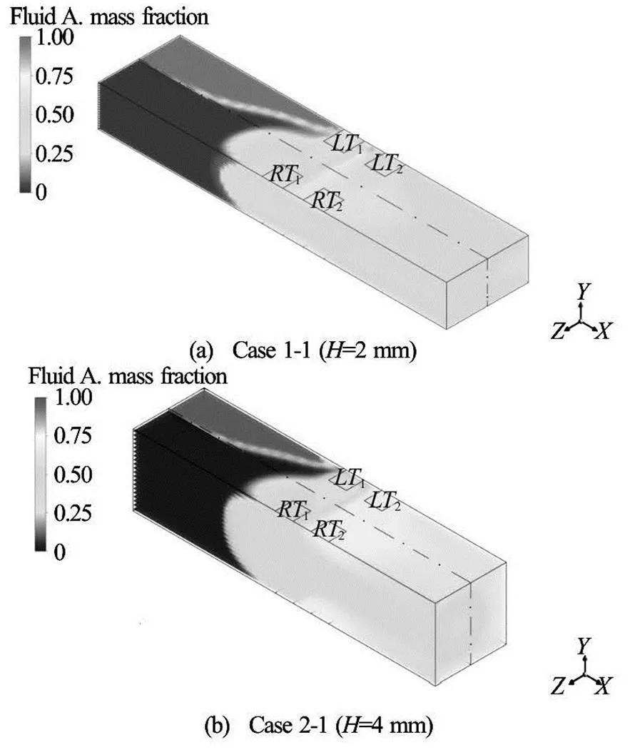
Fig.11 Mass fractions in the situation with one set of electrodes in Case 1-1 and Case 2-1
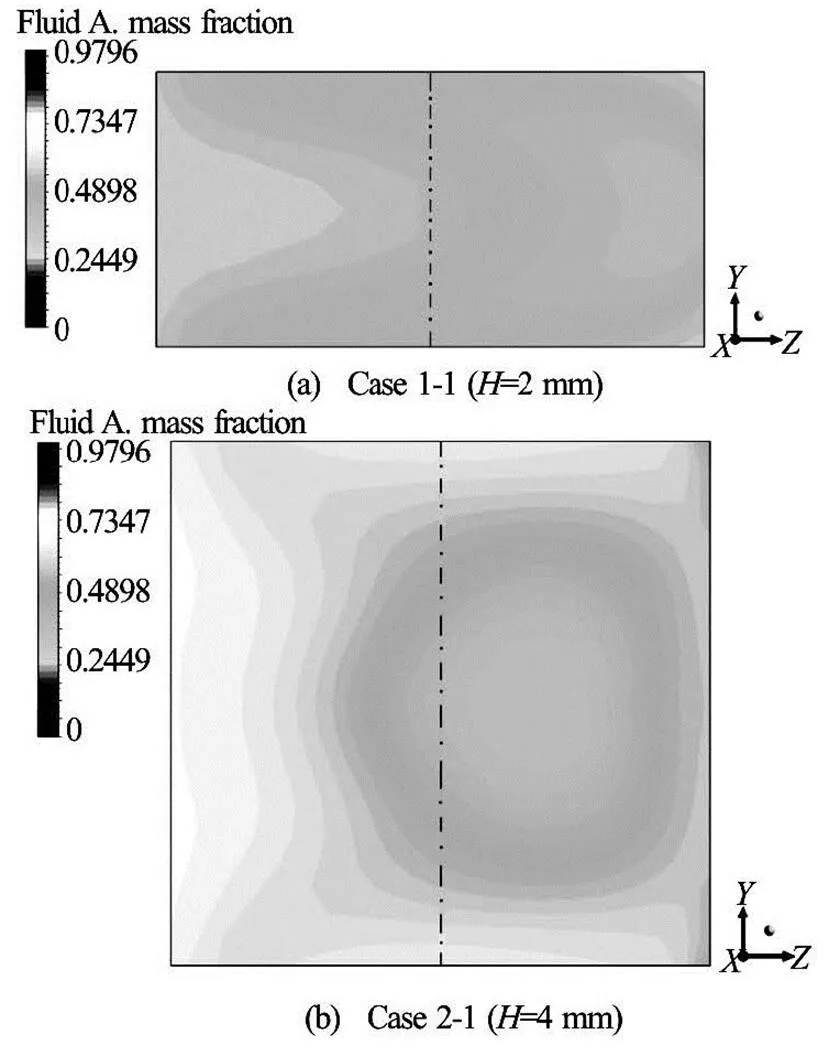
Fig.12 Mass fractions at in the situation with one set of electrodes in Case 1-1 and Case 2-1
3.4
3.4.1 Mixing Indices in Case 1 and Case 2
To quantify the mixer’s performance, the mixing indexcan be defined as follows
Table 3 shows the mixing indicesin Case 1. In each subcase, the mixing index increases with an increase in the number of the electrode set, indicating that the mixing performance can be enhanced by using multiple electrode sets. As depicted in Table 3, the mi- xing indices in the situation with four sets of electro- des are the highest, whose values are 0.99930, 0.99740, 0.98232 in Case1-1, Case 2-1, Case 3-1, re- spectively. When the number of electrode set used is the same, the mixing index increases as the applied electrode voltage (absolute value) increases. With hi- gher input voltage (absolute value) of the electrode, the velocity in the cross-section and the Lorentz force are stronger, yielding better mixing performance. Note that the voltage (absolute value) imposed on the ele- ctrode in Case 1-1 is higher than that in other subcases (Case 2-1, Case 3-1), as shown in Table 1. The mixing indices in Case 1-1 are also higher. Table 4 shows the mixing indicesin Case 2. The tendency of the mixing index observed in Case 1 is again presented in Case 2, where the mixing performance can be enha- nced by using the multiple electrode sets and higher electrode voltage (absolute value). Besides, the mi- xing indices in Case 1are higher than those of Case 2. It is caused by the fact that the Lorentz force in the cross-section in Case 1 is stronger than that of Case 2.
Table 3 Mixing indices in Case 1 1 set2 sets3 sets4 sets Case 1-10.928100.982520.996780.99930 Case 1-20.880580.964900.990440.99740 Case 1-30.782760.910100.959140.98232
Table 4 Mixing indices in Case 2

Table 3 Mixing indices in Case 1
1 set2 sets3 sets4 sets Case 2-10.841520.969180.995920.99844 Case 2-20.762800.913400.975140.98908 Case 2-30.622220.763380.864260.92092
3.4.2 Comparison of the mixing indices in Case 1 and Case 2
As the mixing indices in Case 1 are larger than those of Case 2, the change of the mixing indexcan be estimated by the following equations:
Table 5 shows the values of. It can be noted that the value ofdecreases with an increase in the number of the electrode set. In Table 5, the values ofare the smallest in the situation with four sets of electrodes. The mixing indices for the flow field with four electrode sets in the three subcases of Case 1 are higher by 0.09%, 0.8%, 6.7% than those of Case 2, re- spectively. In addition, the value ofincreases as the input voltage (absolute value) of the electrode de- creases (the number of the electrode set used is the same). It can be reminded that the input voltages (ab- solute value) of the electrode in Case 1-3 and Case 2-3 are the smallest (see Table 1). Here, the values ofare the largest (see Table 5), showing that the differe- nce in the mixing efficiency is the largest between Case 1 and Case 2 when the applied electrode voltage (absolute value) is the smallest.
Table 5 Values of
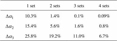
Table 5 Values of
1 set2 sets3 sets4 sets 10.3%1.4%0.1%0.09% 15.4%5.6%1.6%0.8% 25.8%19.2%11.0%6.7%
4. Conclusions
In this study, a new electromagnetic rectangular mirco-mixer with pumping function is devised, and is numerically investigated. Commercial software CFX is used to solve the governing equations. By applying different electric potentials to different electrode sets, the current can be induced. The combination of the in- duced current and magnetic field induces Lorentz force, which can be used for pumping as well as mi- xing.
In order to estimate the mixing performance, the mixing index is used in the present study. The effect of different variables on mixing efficiency is investi- gated in many different cases with two different hei- ghts of the duct and various input voltages of the ele- ctrodes. Meanwhile, the situations with one set, two sets, three sets, four sets of electrodes are considered in each subcase, respectively. The comparison of di- fferent cases leads to the following summaries: First- ly, the mixing index increases with an increase in the number of the electrode set used in each subcase, which means that the mixing performance can be en- hanced by using multiple sets of electrodes. Secondly, the mixing index is higher with higher input voltage (absolute value) of the electrode, indicating that the mixing result will be better if the applied voltage (ab- solute value) is higher. Furthermore, the mixing index is higher with larger aspect ratio of the cross-section.
In conclusion, the present study proposes a new electromagnetic rectangular mircomixer with pumping function, and numerically investigates the mixing cha- racteristics of two different electrolyte solutions in the device in a uniform magnetic field. The current nume- rical results show that high mixing performance can be achieved by the proposed microdevice.
Acknowledgement
This work was supported by the National Resea- rch and Development Program through the National Research Foundation of Korea (NRF) funded by the Ministry of Education, Science and Technology and Ministry of Knowledge Economy (Grant No. 2014045308).
References
[1] QIAN S., BAU H. H. Magneto-hydrodynamics based mi- crofluidics[J]. Mechanics Research Communications, 2009, 36(1): 10-21.
[2] LEE C. Y., CHANG C. L. and WANG Y. N. et al. Micro- fluidic Mixing: A review[J]. International Journal of Molecular Sciences, 2011, 12(5): 3263-3287.
[3] BUCHEGGER W., WAGNER C. and LENDL B. et al. A highly uniform lamination micromixer with wedge shaped inlet channels for time resolved infrared spectroscopy[J]. Microfluidics and Nanofluidics, 2011, 10(4): 889-897.
[4] LIU R. H., STREMLER M. A. and SHARP K. V. et al. Passive mixing in a three-dimensional serpentine micro- channel[J]. Journal of Microelectromechanical Systems, 2000, 9(2): 190-197.
[5] YI M., BAU H. H. The kinematics of bend-induced mi- xing in micro-conduits[J]. International Journal of Heat and Fluid Flow, 2003, 24(5): 645-656.
[6] WANG R., LIN J. Numerical analysis on a passive chaotic micromixer with helical microchannel[J]. Journal of Na- noscience and Nanotechnology, 2006, 6(1): 190-194.
[7] WANG R., LIN J. and LI H. Chaotic mixing on a micro- mixer with barriers embedded[J]. Chaos, Solitons and Fractals, 2007, 33(4): 1362-1366.
[8] MEIJER H. E. H., SINGH M. K. and KANG T. G. et al. Passive and active mixing in microfluidic devices[J]. Ma- cromolecular Symposia, 2009, 279(1): 201-209.
[9] BAU H. H., ZHONG J. and YI M. A minute magneto hy- drodynamic (MHD) mixer, Sens. Actuators B[J]. Sensors and Actuators B Chemical, 2001, 79(2-3): 207-215.
[10] YI M., QIAN S. and BAU H. H. A minute magneto hydro dynamic (MHD) chaotic stirrer[J]. Journal of Fluid Me- chanics, 2002, 468: 153-177.
[11] LA M., KIM W. and YANG W. et al. Design and numeri- cal simulation of complex flow generation in a microcha- nnel by magnetohydrodynamic (MHD) actuation[J]. In- ternational Journal of Precision Engineering and Ma- nufacturing, 2014, 15(3): 463-470.
[12] JANG J., LEE S. Theoretical and experimental study of magneto-hydrodynamic (MHD) micropump[J]. Sensors and Actuators A Physical, 2000, 80(1): 84-89.
[13] LEMOFF A. V., LEE A. P. An AC magneto-hydrodyna- mic micro-pump, Sens. Actuators B[J]. Sensors and Ac- tuators B Chemical, 2000, 63(3): 178-185.
[14] ZHONG J., YI M. and BAU H. H. Magneto-hydrodyna- mic (MHD) pump fabricated with ceramic tapes[J]. Sen- sors and Actuators A Physical, 2002, 96(1): 59-66.
[15] BAU H. H., ZHU J. and QIAN S. et al. A magneto-hydro- dynamically controlled fluidic network[J]. Sensors and Actuators B Chemical, 2003, 88(2): 205-216.
[16] FANG Y., YE Y. and SHEN R. et al. Mixing enhanceme- nt by simple periodic geometric features in microchanne- ls[J]. Chemical Engineering Journal, 2012, 187(2): 306- 310.
[17] HUTCHINSON B. R., RAITHBY G. D. A multigrid me- thod based on the additive correction strategy[J]. Numeri- cal Heat Transfer, 1986, 9(5): 511-537.
[18] RAW M. Robustness of coupled algebraic multigrid for the Navier-Stokes equations[C]. 34th Aerospace Sciences Meeting and Exhibit. Reno, Nevada, USA, 1996, 96- 0297.
* Biography: Meimei WEN (1991-), Female,Master Candidate
Corresponding author: Chang Nyung KIM, E-mail: cnkim@khu.ac.kr
10.1016/S1001-6058(16)60613-3 2016,28(1):114-124
杂志排行
水动力学研究与进展 B辑的其它文章
- Flow, thermal criticality and transition of a reactive third-grade fluid in a pipe with Reynoldsʼ model viscosity*
- Investigation of the effects of platform motion on the aerodynamics of a floating offshore wind turbine*
- A new biomimicry marine current turbine: Study of hydrodynamic performan- ce and wake using software OpenFOAM*
- Study of bedload transport in backwater flow*
- Experimental study of water and dissolved pollutant runoffs on impervious surfaces*
- A numerical model for pipelaying on nonlinear soil stiffness seabed*