气液分离强化传热多孔结构毛细上升特征
2016-08-06涂文斌
涂文斌,王 匀,汤 勇
气液分离强化传热多孔结构毛细上升特征
涂文斌1,王匀1,汤勇2
(1江苏大学机械工程学院,江苏 镇江 212013;2华南理工大学机械与汽车工程学院,广东省高校表面功能结构制造重点实验室,广东 广州 510640)
摘要:气液分离强化传热多孔结构,由于气体、液体在多孔壁面有着不同的力学行为,使得气液两相在多孔壁面发生分离,气体不能进入多孔壁面结构,液体则能自由进入,从而形成气体始终沿管壁运动,液体则在管中心流动这一高效传热流态。多孔壁面的毛细力对气液分离有着重要的影响。采用一种新颖的毛细力测试方法——红外热像测试法测试了多孔强化结构的毛细力。研究发现,多孔结构的毛细力与使用的粉末材料形状、颗粒尺寸及填充孔隙率有关。其中对毛细力影响最大的是粉末颗粒形状,颗粒尺寸次之,孔隙率最弱。
关键词:毛细力;烧结;多孔介质;传热;红外热像
引 言
强化传热技术可划分为被动式强化技术和主动式强化技术[1],被动式强化技术不需要外界动力,包括扩展表面、插入物、涡流发生器等;主动式强化技术则需要加入外部动力,包括机械振动、施加电场磁场、流体添加物等。管内强化通常有插入物、内翅片及扩展表面等[2-4]。这些传热强化技术的物理机制可归纳为:(1)壁面区和中心区流体的混合;(2)流体边界层减薄;(3)二次流形成、增强湍流强度[5-7]。气液分离强化传热是作者所在课题组2012年提出的一种新型强化传热方法[8-9],该方法利用气液两相在多孔壁面有着不同的力学行为,气液两相能够在多孔壁面发生分离,其中气体不能进入多孔壁面结构,液体则能自由进入,从而形成气体始终沿管壁运动,液体则在管中心流动这一高效传热流态。多孔壁面的毛细力对气液分离有着重要的影响。本文采用一种新颖的毛细力测试方法——红外热像测试法测试了多孔强化结构的毛细力,研究多孔结构使用的粉末材料形状、颗粒尺寸及填充孔隙率对毛细力的影响。
毛细力测试方法有气泡法、毛细上升法[10-11]。大多数研究人员一般采用毛细上升的方法进行测量[12-15],不同于一般毛细上升法,本项目团队[16-20]提出一种红外热像仪测试毛细高度的方法。该方法主要利用了不同物体的发射率不一样,在红外热像仪测温时,对特定的物体需设定其对应的发射率,否则测试出来的温度不是物体本身的温度,而是和发射率呈一个比例关系。这个特点可以用于多孔毛细力的测试。当毛细测试采用的工质其反射率同测试样品反射率相差非常大时,样品和工质的温度即使一样,它们在红外仪上的热像图将会产生巨大的差异,这种图像上的差异可以用来测试毛细上升的高度。该方法同其他方法相比,测试结果更加直观,其精度也非常高。

图1 烧结成品Fig.1 Picture of samples
1 测试样品准备
气液分离强化传热多孔结构采用铜质粉末固相烧结的方法制造,烧结设备为KBF16Q3,功率为8 kW,工作电压220 V,频率50 Hz,炉膛尺寸300 mm×200 mm×200 mm。样品有3组,第1组使用不同尺寸铜粉颗粒,第2组使用不同形状铜粉颗粒,第3组使用不同填充量即不同孔隙率,所有样品都是在气氛炉900℃环境下烧结1 h而成,烧制而成的样品如图1所示。
2 实验装置及测试方法
毛细多孔样品产生的上升压力可以表示为

式中,σ为液体的表面张力;θ为三相界面形成的浸润角;r为毛细孔径。
液体在毛细力的驱动下上升,上升的过程中将受到重力的作用,此外还受到运动过程中黏滞力的作用,其力学平衡方程为

方程右边第1项为重力产生的水力压头,第2项为流体通过多孔介质产生的压差,其数值由达西定理推导而出,μ为黏度,u为液体流速,ε为孔隙率,Kp为渗透率。因此,当测试时间足够长时,液体毛细上升高度可以表示毛细力的大小。
本文使用红外热像仪来测量样品的毛细上升高度。测试用的工质采用反射率同测试样品反射率相差非常大的甲醇,虽然样品和工质的温度一样,由于反射率相差巨大,它们在红外仪上的热像图差异巨大,这种图像上的差异可以方便地观测到工质毛细上升的高度。
毛细红外热像测试装置由观察室、红外热像仪、数据采集PC等3部分组成。由于红外热像仪具有高度的热敏感性,测试结果极容易受到环境的影响,空气流动、热源、光线反射、物体材质甚至人体等都会对结果参数产生不利影响,因此测试环境最好是封闭式防辐射环境。本文采用的观察室是半封闭式黑色箱体,箱体黑色表面用来消除四周的反射;为了便于观察及操作,封闭箱体开了一个小门。观察室内有一样品固定装置,样品固定在装置的水平横梁上,样品保持竖直。工质放在一个蒸发皿内,工质和样品接触由一水平升降台上下调节位置。测试过程首先连接好测试装置,固定好测试样品,一切准备就绪。先将蒸发皿倒满甲醇,然后关上箱体门,让甲醇在观察室内自由蒸发,20 min后,观察室甲醇蒸气饱和,开始进行测试。调节升降台,让样品浸入甲醇溶液,测试过程中人员和观察室保持一定距离,以免产生不利影响。测试时间为 10 min,采样时间3 min。红外仪测量精度为1%,长度测量误差为1.3%,毛细上升高度的测量不确定度为1.5%。
采样后的红外热像图如图 2所示。测试样品为圆柱状物体,蓝色部分为吸入样品中的甲醇,图中显示毛细高度清晰可辨,实验效果良好。但实验取样高度并不是通过图像目测测量而得,而是采用样品表面温度分析得到。首先在样品中心做一根温度采样线,图2中样品中间那根线即是温度采样线。
通过热像仪分析软件,可以获得这根采样线的温度分布。其温度分布如图3所示,其温度从低往高变化,毛细液弯位置应处在温度突变的地方,因此,图3温度曲线中垂直的地方(黑色框区域)即是毛细液弯处,温度曲线垂直的地方温度必然发生了突变。

图2 调控管红外毛细上升图Fig.2 IR thermal image of capillary rise of sample

图3 直线L1温度变化曲线Fig.3 Temperature curve of Line 1
3 结果分析
3.1 粉末颗粒尺寸的影响
3种不同直径颗粒枝状烧结棒作为测试样品,其颗粒尺寸分别为<25 μm、100~125 μm和>150 μm,颗粒尺寸采用分层筛子对铜粉进行分筛获得。样品孔隙率为0.76左右,所有样品在气氛炉900℃烧结1 h而成。测试样品参数、烧结工艺见表1。

表1 枝状毛细测试样品Table 1 Samples with branch shape
样品测试红外热像图如图4所示,上升曲线图见图5,采样时间为3 min。图4中的3根样品从左到右分别为Cu-Bran-25(枝状<25 μm),Cu-Bran-125(枝状 100~125 μm),Cu-Bran-150(枝状>150 μm)。0~40 s时,Cu-Bran-150(枝状>150 μm)表现最为优越,其上升速度最快,图4中前5幅图能明显看出最右侧样品毛细上升最高,Cu-Bran-25(枝状<25 μm)表现最差,上升高度最小。这主要是因为颗粒形状越小,颗粒间组成的空隙越小,此外,由于细小颗粒在烧结成型的过程中,其细小的末梢会融化,颗粒间的孔洞甚至闭合,样品空隙结构不十分理想,因此渗透率也就越小,流体上升的阻力就越大。
图6显示了Cu-Bran-25和Cu-Bran-150样品SEM图。图中显示Cu-Bran-25样品其铜粉颗粒末端几乎都成圆形,这是因为铜粉颗粒太小,在烧结的过程中极易发生融化迁移,由于表面张力的作用变成了圆形,此外颗粒间的空隙有发生融合变小的现象。图6(b)中Cu-Bran-150样品则没有发生这种现象,其孔洞仍然保持原貌,颗粒间的连接黏合在100 μm尺度中几乎看不见,孔洞分布比较均匀,有利于流体的运动。因此在毛细测试中,样品Cu-Bran-25表现较弱便在情理之中。
有意思的是,当时间大于 40 s时,样品Cu-Bran-125高度超越了样品Cu-Bran-150高度,70、 180 s时,红外热像图清楚地显示位于中间位置样品Cu-Bran-125毛细上升高度要高于其他两个样品。这是因为当时间大于40 s时,流体上升速度下降,流体运动产生的阻力减弱,此刻上升液体产生的压力差占据主要因素,由于毛细力的大小和当量孔径的大小呈正比,Cu-Bran-125样品由于颗粒较细,在烧结的过程中孔隙也没有破坏,因此其产生的毛细力要大于大径粒 Cu-Bran-150样品产生的毛细力,其上升的高度因此要优于其他样品。

图4 枝状铜粉调控管红外热像图Fig.4 IR thermal images of capillary rise of samples with branch shape

图5 枝状颗粒样品毛细上升曲线Fig.5 Capillary rise height over time of samples with branch shape
3.2 颗粒形状的影响
采用同尺度100~125 μm颗粒球形粉末和枝状粉末样品进行比较,球形粉末和枝状粉末大小虽然一致,但其孔隙率相差悬殊,球形为0.29,枝状为0.75。图7显示两种不同样品毛细上升曲线,图中显示两样品性能相差较大,无论是在毛细上升的初期,还是在毛细上升的末期,枝状粉末样品性能都优于球状粉末。25 s以后,枝状粉末样品明显要高于球状粉末样品,随着时间的延长,两者的高度有加大的趋势,但不太明显。虽然枝状粉末和球状粉末颗粒大小一样,但由于孔隙率相差悬殊,枝状粉末孔洞结构要大于球状粉末结构,且孔洞连接方式更加丰富,因此毛细性能较球状粉末优越,流动阻力也相对较低,因此在使用调控多孔结构时,枝状粉末要优于球形粉末。此外,枝状粉末填充量较小,几乎是同尺寸球状粉末的一半,非常节省材料,可降低制造成本。

图6 枝状颗粒烧结样品SEM图Fig.6 SEM picture of samples with branch shape

图7 不同颗粒形状样品毛细上升曲线Fig.7 Capillary rise height over time of samples with different shape
3.3 孔隙率的影响
对于孔隙率的影响,采用同尺度、不同厂家生产的枝状铜粉,所有样品采用900℃烧结1 h工艺烧结,其孔隙率分别为0.72、0.75和0.56,其参数见表2。其毛细上升曲线如图8所示,在80 s之前,三者毛细上升曲线几乎重合,3种样品性能很难区分出来;当时间大于80 s时,3条曲线开始分开。毛细上升高度和孔隙率呈一定的反比关系,孔隙率越高,其毛细上升高度越低。样品Cu-Bran-3125孔隙率最低为0.57,因此其当量毛细半径最小,产生的毛细压力最大,毛细上升高度最高。特别值得注意的是,三者毛细上升高度虽然有差别,但差别较小,同颗粒尺寸相比,孔隙率大小对毛细力的影响相对弱很多。
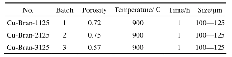
表3 枝状不同批次毛细测试样品Table 2 Samples with branch shape from different manufactories

图8 不同孔隙率枝状颗粒样品毛细上升曲线Fig.8 Capillary rise height over time for samples with branch shape
4 结 论
多孔金属调控结构的毛细特性受到粉末尺寸、孔隙率、粉末形状及烧结工艺参数的影响。其中粉末尺寸对毛细影响较大,在3个不同尺寸大小的枝状颗粒样品中(<25 μm,100~125 μm和>150 μm),其毛细特征不呈线性关系,最优值为颗粒尺寸100~125 μm样品,该样品毛细力极大,同时毛细上升流动阻力较小。粉末形状对毛细影响较大,球状粉末毛细特性表现优良,但由于流动阻力较大,其综合性能还是弱于枝状样品。孔隙率对毛细特性的影响较弱,远不如颗粒形状、颗粒尺寸。
References
[1] BERGLES A E. ExHFT for fourth generation heat transfer technology [J]. Experimental Thermal and Fluid Science, 2002, 26: 335-344.
[2] TU W B, TANG Y, ZHOU B, et al. Experimental studies on heat transfer and friction factor characteristics of turbulent flow through a circular tube with small pipe inserts [J]. International Communications in Heat and Mass Transfer, 2014, 56: 1-7.
[3] JI W T, ZHAO C Y, ZHANG D C, et al. Influence of condensate inundation on heat transfer of R134a condensing on three dimensional enhanced tubes and integral-fin tubes with high fin density [J]. Applied Thermal Engineering, 2012, 38: 151-159.
[4] 谭羽非, 陈家新. 新型不锈钢波纹管性能及强化传热的实验研究[J]. 热能动力工程, 2003, 18(1): 47-49.
TAN Y F, CHEN J X. Experimental study on the performance of a new type of stainless steel corrugated tube [J]. Journal of Engineering for Thermal Energy and Power, 2003, 18(1): 47-49.
[5] 过增元, 黄素逸. 场协同原理与强化传热新技术[M]. 北京: 中国电力出版社, 2004.
GUO Z Y, HUANG S Y. Principle of Cooperative Field and New Technology of Heat Transfer Enhancement [M]. Beijing: China Electric Power Press, 2004.
[6] 孟继安, 陈泽敬, 李志信, 等. 交叉缩放椭圆管换热与流阻实验研究及分析[J]. 工程热物理学报, 2004, 25(5): 813-815.
MENG J A, CHEN Z J, LI Z X, et al. Experimental study and analysis on heat transfer and flow resistance of elliptical tube with cross scaling [J]. Journal of Engineering Thermalphysics, 2004, 25(5): 813-815.
[7] WANG P, LIU D Y, XU C. Numerical study of heat transfer enhancement in the receiver tube of direct steam generation with parabolic trough by inserting metal foams [J]. Applied Energy, 2013, 102: 449-460.
[8] CHEN H X, XU J L, LI Z J, et al. Flow pattern modulation in a horizontal tube by the passive phase separation concept [J]. International Journal of Multiphase Flow, 2012, 45: 12-23.
[9] 陈宏霞, 徐进良, 李子衿, 等. 相分离概念调控水平管分层流流型[J]. 化工学报, 2012, 63(7): 2045-2050.
CHEN H X, XU J L, LI Z J, et al. Stratified flow pattern modulation by phase separation concept [J]. CIESC Journal, 2012, 63(7): 2045-2050.
[10] ADKINS D R., DYKHUIZEN R C. Procedures for measuring the properties of heat pipe wick materials [C]// Proceedings of the 28th Intersociety Energy Conversion Engineering Conference, 2010: 911-917.
[11] FREGGENS R A. Experimental determination of wick properties for heat pipe applications [C]// 4th Intersociety Energy Conference Engineering Conference. Washington, DC, 1969: 888-897.
[12] WEIBEL J A, GARIMELLA S V, NORTH M T. Characterization of evaporation and boiling from sintered powder wicks fed by capillary action [J]. International Journal Heat and Mass Transfer, 2010, 53(19/20): 4204-4215.
[13] HOLLEY B, FAGHRI A. Permeability and effective pore radius measurements for heat pipe and fuel cell applications [J]. Applied Thermal Engineering, 2006, 26(4): 448-462.
[14] HWANG G S, NAM Y, FLEMING E, et al. Multi-artery heat pipe spreader: experiment [J]. International Journal of Heat and Mass Transfer, 2010, 53(11/12): 2662-2669.
[15] BYON C, KIM S J. Capillary performance of bi-porous sintered metal wicks [J]. International Journal of Heat and Mass Transfer, 2012, 55(15/16): 4096-4103.
[16] 邓大祥. 微尺度热质输运强化槽道多孔结构制造及性能研究[D].广州: 华南理工大学, 2013.
DENG D X. Fabrication and properties of micro scale heat and mass transport through porous structure [D]. Guangzhou: South China University of Technology, 2013.
[17] DENG D X, TANG Y, ZENG J, et al. Characterization of capillary rise dynamics in parallel micro V-grooves [J]. International Journal of Heat and Mass Transfer, 2014, 77: 311-320.
[18] DENG D X, TANG Y, HUANG G H, et al. Characterization of capillary performance of composite wicks for two-phase heat transfer devices [J]. International Journal of Heat and Mass Transfer, 2013, 56: 283-293.
[19] TANG Y, DENG D X, HUANG G H, et al. Effect of fabrication parameters on capillary performance of composite wicks for two-phase heat transfer devices [J]. Energy Conversion and Management, 2013, 66: 66-76.
[20] TANG Y, DENG D X, LU L S, et al. Experimental investigation on capillary force of composite wick structure by IR thermal imaging camera [J]. Experimental Thermal and Fluid Science, 2010, 34: 190-196.
2015-09-10收到初稿,2016-04-06收到修改稿。
联系人及第一作者:涂文斌(1979—),男,博士,讲师。
Received date: 2015-09-10.
中图分类号:TB 657.5
文献标志码:A
文章编号:0438—1157(2016)07—2761—06
DOI:10.11949/j.issn.0438-1157.20151434
基金项目:国家自然科学基金项目(U0934005,51575245);国家重点基础研究发展计划项目(2011CB710703);江苏大学高级人才启动基金项目(15JDG151)。
Corresponding author:TU Wenbin, 13912145@qq.com supported by the National Natural Science Foundation of China (U0934005,51575245), the National Basic Research Program of China(2011CB710703) and the Jiangsu University Scientific Research Foundation for Advanced Talents (15JDG151).
Capillary performance of metal porous media for heat transfer enhancement
TU Wenbin1, WANG Yun1, TANG Yong2
(1School of Mechanical Engineering, Jiangsu University, Zhenjiang 212013, Jiangsu, China;
2Key Laboratory of Surface Functional Structure Manufacturing of Guangdong Higher Education Institutes, School of Mechanical and Automotive Engineering, South China University of Technology, Guangzhou 510640, Guangdong, China)
Abstract:Metal porous media which enables the gas and liquid separation is adopted to enhance heat transfer. Due to the different mechanical behavior between gas and liquid in the porous wall, the gas-liquid two-phase can be separated along the porous media insert, where gas cannot enter the porous wall and the liquid is free to flow in the center. Thus, the gas can flow along the tube wall and the liquid flow in the center of the tube, leading to a high heat transfer performance. Capillary force of the porous media has an important influence on the enhancement performance. In this paper, a novel capillary force testing method is used to test the capillary force of the metal porous media inserts. It is found that the capillary force of the porous media is associated with the powder material, particle size and the filling of the porosity. The particle shape is the most important factor affecting the capillary force and then the particle size, while the porosity is the weakest one.
Key words:capillary force; sintering; porous media; heat transfer; infrared thermograph
