Research on drilling parameters of engine-powered auger ice drill
2016-07-15MikhailSysoevandPavelTalalay
Mikhail Sysoev and Pavel Talalay
PolarResearchCenter,JilinUniversity,Changchun130026,China
Research on drilling parameters of engine-powered auger ice drill
Mikhail Sysoev and Pavel Talalay
PolarResearchCenter,JilinUniversity,Changchun130026,China
Abstract:Drilling operations in polar regions and mountainous areas are complicated by nature of the extreme environment. Yet conventional rotary drilling technologies can be used to drill ice for scientific samples and other research. Due to such reasons as power consumption and weight complications, it is hard to apply a conventional rotary drilling rig for glacial exploration. Use of small, relatively lightweight, portable engine-powered drilling systems in which the drill lifting from the borehole is carried by the winch. It is reasonable enough for near-surface shallow ice-drilling down to 50 m. Such systems can be used for near-surface ablation-stakes installation, also temperature measurements at the bottom of active strata layer, revealing of anthropogenic pollution, etc. The specified used in this research is an auger ice drill powered by a gasoline engine. At this stage, it is crucial to choose effective drilling parameters such as weight on bit (WOB) and drill bit rotation rate. Sensors equipped on the rig have measured the main parameters of the drilling process, such as drill speed, WOB, drill rotation speed, torque and temperature. This paper addresses research on drilling parameters of engine powered auger ice drill and supplies some recommendations for optimization of any ice-core drilling process.
Key words:engine-powered auger ice drill; gasoline engine; drilling parameters; rate of penetration (ROP); weight on bit (WOB); torque
1Introduction
Drilling operations in polar regions and mountainous regions are complicated by extreme low temperatures at the surface and within the glaciers, glacier flow, absence of roads and infrastructures, storm force winds and snowfalls, etc. In principle, it would be possible to use the conventional rotary drilling technology for drilling in ice, and early rotary drilling yielded acceptable drilling rates (Lange, 1973). However, considering the power consumption rates and the weight of conventional rotary drilling rigs, they are difficult to adapt and to be applicable for glacial exploration. For ice, drilling special purpose-built drilling equipment and technology was designed and explored in various institutes all over the world.
Near-surface shallow drilling in ice within to 50m serves the purpose of ablation-stakes installation, temperature measurements at the bottom of active strata layer, revealing of anthropogenic pollution, etc. To these ends, it makes sense to use small, relatively lightweight, portable drilling systems in which lifting of the drill from the borehole is carried by the winch (Koci & Kuivinen, 1984; Rand & Mellor, 1985; Kyne & McConnell, 2007). To drill down to the depth of approximately 50m it is reasonable to use engine-powered auger systems that do not require a drilling fluid.
The important stage of drilling technology planning is choosing effective drilling parameters which include weight on bit (WOB) and drill bit rotation rate. Many factors affect the drilling parameters, such as the mechanical properties of the ice to be drilled, type of the drill bit, capacity and power or mechanical force of the drilling rig. This paper addresses research on drilling parameters of gasoline engine-powered auger ice drill and gives some recommendations for optimization of ice-core drilling process.
2Experimental engine-powereduger ice drill
Experimental engine-powered auger ice drill consists of sledge, main mast, extra mast, top wheel, winch, drive unit and drill (Fig.1). The sledge has modular construction. It consists of a pair of skies and two welded frames, bolted together. In the middle of the sledge, the main 2 m height mast is mounted. The main mast consists of two channels bolted together both top and bottom by screws. Inside the channels, the support is installed, able to move up and down. The main mast additionally fixed by two crossbars, coming from the top to the edge of the sledge. The extra mast also is mounted on the sledge behind the main mast. At the top of the extra mast, the top wheel is installed. On the top wheel, four sensors are installed-encoder and three load cell sensors. On the support, the drive unit is installed. The drive unit consists of gasoline engine, gear reducer and torque sensor. The gear reducer is fixed on the support by four screws. Gasoline engine is installed on the gear reducer. The torque sensor is fixed on the output shaft of the gear reducer. To prevent rotation of the torque sensor’s body, it is an immovable fixed armature. The drill is installed on the output shaft of the torque sensor secured by one screw. The winch is installed on the sledge as well as both masts. The winch consists of one AC motor, cycloidal reducer, worm-gear reducer, drum, and frequency controller. To move the support up and down a 5 mm diameter Kevlar rope is used. It is routed from the winch through the top wheel to the support.
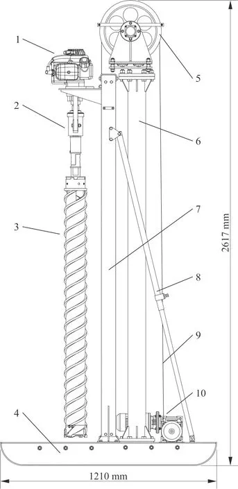
1. gasoline engine; 2. torque sensor; 3. drill; 4. sledge; 5. top wheel; 6. extra mast; 7. mast; 8. crossbars; 9. kevlar rope; 10. winch.Fig.1 Layout of experimental engine-powered auger ice drill
To drive the core barrel, the air-cooled 2-stroke gasoline engine of Sanbang type is used. The net power output of the engine is 3.2 kW, and the output rotation rate is ~340 rpm. The engine can operate at temperatures down to -40℃.
The winch is driven by motor-reducer system with motor of YW3024 type and two gears consisted of worm reducer of RV50 type and cycloidal reducer of WB65 type. The nominal rotation speed of the motor is 1 440 rpm and overall gear ratio is 1 290∶1. The output shaft rotation speed is ~1 rpm with maximal torque of 266 Nm. The rotation speed of themotor is regulated through frequency controller of VFD015M43B type.
3Control system
In the course of experiments, the following parameters and variables were measured:
Drill speed registered by an encoder of BCE58S10 type, installed on the top wheel shaft;
WOB registered by three load cell sensors of JHBM-50 type, installed under the top wheel;
Drill rotation speed registered by a RPM sensor, installed on reducer output shaft;
Torque registered by a torque sensor of LKN-205 type, installed on reducer output shaft;
Ice temperature registered by a temperature sensor of DS18B20 type by being frozen-in ice;
Air temperature registered by an open-air thermometer.
To collect needed data from the torque sensor and load cell sensors; data acquisition modules ADAM 4080 and ADAM 4017+ were used. Encoder and temperature sensors have their own data acquisition modules. For working with data acquisition modules, an x86-processor architecture laptop computer was used. All modules were connected to a laptop computer using adapters HL-340 via USB and RS-232 I/O ports, located on the docking station. The temperature sensor was connected via USB directly using the built-in 1-wire to USB adapter. To monitor the data on the screen and subsequent storing of said data software LabVIEW 2014 was used. As the computer operating system, 64 bit Windows was used.
4Experimental method
Test stand is installed and fixed on the table (Fig.2). To test drilling process as close to the real drilling conditions as in the field as possible, blocks of the natural lake ice with sizes of 0.7×0.6×0.5 m were used for the test drilling. These blocks were installed under the test stand. The drill head cutters were made from tool steel (W18Cr4V) with a 15mm width, a rake angle of 60°, a relief angle of 15° and a 100mm ID. Before each testing run, the cutters were carefully sharpened.
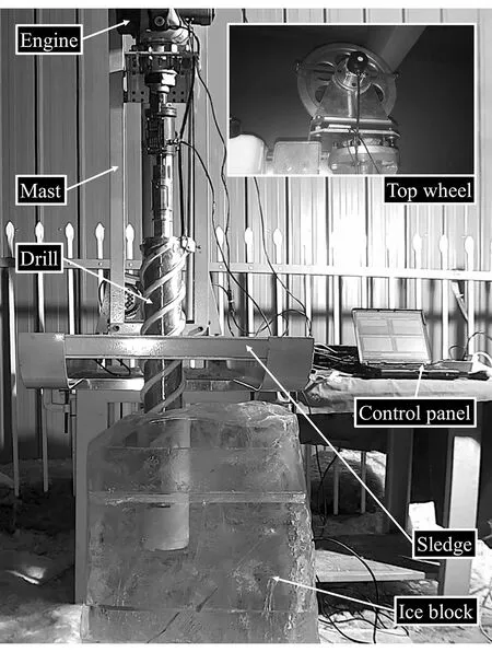
Fig.2 Testing procedure
By practical consideration it has been determined when at a frequency of 40 Hz from the winch motor power-supply voltage, the drill reaches near to the quickest rate of pentation (ROP) using almost all the available weight of 300N. That is why frequency values 10 Hz, 20 Hz, 30 Hz and 40 Hz were selected for experiments
The minimum rotation speed at which the gasoline engine was able to create enough torque for cutting ice was 170 RPM. The maximum RPM is over 340 RPM. For the experiment 170, 200, 240 and 280 RPM were selected with fluctuations of near ±10 due to the complexity of controlling rotation speeds of the gasoline motor.
It was decided to make four series of experiments for four boreholes per each series. The method kept drill rotation speed constant, and would change the drill’s speed per each experiment that was run. A total of 16 experiments were planned, but only 15 were carried out. Unfortunately, the last experiment failed because the motor cannot provide enough torque anymore for drilling ice at 170 RPM. It was quite difficult to start the hole. It was discovered that the drill could easily deviate (walk) from the target. As a result, it was impossible to start drilling unless the drill was already centered, in our case in the borehole for the depth of at least 10mm. This was done by slowly turning the drill to create a divot (pre-hole) to begin main drill operations.
5 Conclusions
The record of the normal testing run is shown on Fig.3. A part of stable drilling with length of 100 mm has been selected from each record and average parameters were chosen (Table 1).
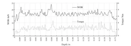
Fig.3 Recording of the WOB and drilling torque during run #5
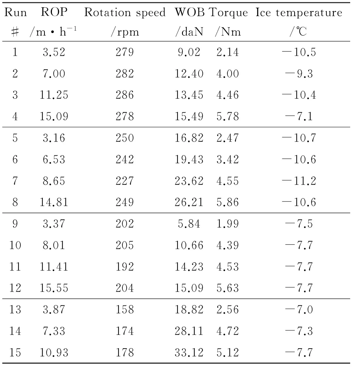
Run#ROP/m·h-1Rotationspeed/rpmWOB/daNTorque/NmIcetemperature/℃13.522799.022.14-10.527.0028212.404.00-9.3311.2528613.454.46-10.4415.0927815.495.78-7.153.1625016.822.47-10.766.5324219.433.42-10.678.6522723.624.55-11.2814.8124926.215.86-10.693.372025.841.99-7.5108.0120510.664.39-7.71111.4119214.234.53-7.71215.5520415.095.63-7.7133.8715818.822.56-7.0147.3317428.114.72-7.31510.9317833.125.12-7.7
Dependence of the WOB and torque from ROP at constant rotation speeds are shown in Fig.4. While increasing ROP, WOB and torque are increasing. Dependence of the torque from rotation speed at constant ROP is shown in Fig.5. It is evident that there is not any correlation between torque and rotation speed.
During the experiment, it was discovered that max torque required did not exceed the value of 10 Nm. The average value of torque was measured as 4--5 Nm. Therefore, it is reasonable to use an engine with less power for drilling ice and select a proper reducer to prevent torque problems at low RPMs.
As shown previously, rotation speed does not have direct influence on the torque, that’s why optimal rotation speed should be selected based on other para-meters, such as efficiency of ice cuttings’ transportation.
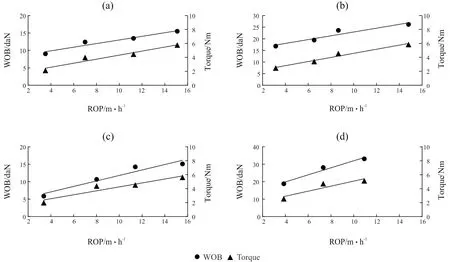
(a) 280 rpm; (b) 240 rpm; (c) 200 rpm; (d) 170 rpmFig. 4 WOB and torque vs ROP at constant rotation speed
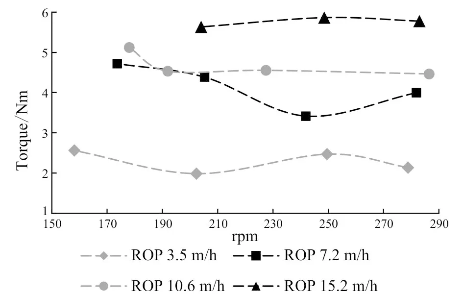
Fig.5 Torque vs rotation speed at ROP
In general, conception of the experimental engine-powered auger ice drill looks quite workable and with proper improvement it would be possible to test it in the field. In the near future, it is planned to make improvements of the engine-powered auger ice drill, for example, to change the motor for more reliable type and improve design of the mast. In addition, it makes sense to conduct another series of experiments with a different design of the “ice drill” cutters.
Acknowledgements
We thank A. Markov and J. Hong for their advices.
Language accuracy is by courtesy of Justin Hill, Changchun University of Technology and Business, from Jilin Agricultural University, Trinity College London Edinburgh, Ashford University, Clinton Iowa, Texas A&M University.
References
Koci B R, Kuivinen K C. 1984. The PICO lightweight coring auger.JournalofGlaciology, 30(1): 244--245.
Kyne J, McConnell J. 2007. The prairie dog: a double-barrel coring drill for hand augering.AnnalsofGlaciology, 47(1): 99--100.
Lange G R. 1973. Deep rotary core drilling in ice. Hanover NH: Cold regions research and engineering laboratory, technical report.
Rand J, Mellor M. 1985. Ice-coring augers for shallow depth sampling. US army cold regions research and engineering laboratory report.
doi:10.3969/j.issn.1673-9736.2016.01.01
Article ID: 1673-9736(2016)01-0001-05
Received 15 September 2015, accepted 25 October 2015
Supported by projects of National Science Foundation of China (No. 41327804) and the Geological Survey of China (No. 3R212W324424)
杂志排行

Global Geology的其它文章
- Delineation of Haigou gold metallogenic province and its metallogenic prospection
- Random seismic noise attenuation by learning-type overcomplete dictionary based on K-singular value decomposition algorithm
- Inversion of 3D density interface with PSO-BP method
- Downhole microseismic data reconstruction and imaging based on combination of spline interpolation and curveletsparse constrained interpolation
- Oil shale resources in China and their utilization
- Distributive characteristics of reservoirs and exploration potential associated with intrusive rocks of Yingcheng Formation in Yingtai rift depression, NE China