High-Frequency Components in Numerical Wave Trains
2016-05-16
(State Key Laboratory of Ocean Engineering,Shanghai Jiao Tong University,Shanghai 200240,China)
High-Frequency Components in Numerical Wave Trains
GAO Ning-bo,YANG Jian-min,LI Xin
(State Key Laboratory of Ocean Engineering,Shanghai Jiao Tong University,Shanghai 200240,China)
The reliability and repeatability of modelling waves is of great importance for the estimation of hydrodynamics of offshore structures.In this study,the commercial software package Fluent is used to simulate regular waves in four different mesh conditions.The free surface is captured using the Volume of Fluid(VOF)method.Dynamic mesh method is used to realize the flap-type wavemaker motion.Given the numerical dissipation and truncation errors during numerical simulations, wave decay along the tank is checked and controlled within a reasonable range.To avoid disturbances induced by the starting of the flap movement,a fade-in method is adopted at the first 4 sec simulation.Regular waves are generated and compared with linear wave theory results and secondorder wave theory results,respectively.The results show that the developed model based on VOF technique is able to provide reliable predictions.This developed model is expected to serve as a basis for strongly nonlinear waves,such as freak waves.
Volume of Fluid;fade-in;regular wave;second-order wave
0 Introduction
Wave-structure interactions are of great importance for the design of an offshore structure.Regenerating waves numerically or experimentally is essential for the hydrodynamic prediction of the responses of offshore structures in waves.One of the most common approaches is to conduct model test in physical wave tanks,such as MARINETEK in Norway,MARINE in Netherland,SKLOE in China,etc.The most advantage of model test is that the real hydrodynamics can be modelled,measured and filmed as often as necessary[1].In fact,experimental studies can not only provide basic insights into the inherent mechanism,but also serve as validation of numerical models.However,due to the high expense and limitation in scale effect, numerical simulations are still necessary.
With the development of computational technology,effective numerical simulation of water waves is possible.There have been lots of studies on how to reproduce waves numerically. Chappelear[2]first introduced a numerical high-order wave theory for highly nonlinear waves based on stream function wave theory.This study was further developed[3-5].Internal wave gen-eration models were also developed for generating waves,avoiding the interference with the boundary conditions.Brorsen and Larsen[6]proposed source generation of nonlinear gravity waves with the boundary integral equation method.Zhao et al[7]developed a numerical method for modeling nonlinear water waves based on the High Order Spectral(HOS)method.Bai and Eatock Taylor[8]used boundary element method(BEM)to simulate the process of fully nonlinear regular wave and focused wave.Kim et al[9]performed fully nonlinear multidirectional waves by a 3-D viscous numerical wave tank based on a finite-difference scheme and a modified marker-and-cell method.Clauss et al[10]combined the advantages of potential-theory wave tank and RANS/VOF wave tank.Potential-theory wave tank was used to simulate wave train propagation before wave-breaking occurred.Subsequently,the value of velocity field and the free surface calculated in potential-theory wave tank was transferred as boundary or initial values to the RANSE/VOF-solver and the simulation process was continued.Validation was made against experimental results.Based on linear wave-maker theory,Wang[11]developed a numerical wave channel.Absorbing wave-maker boundary is set up at one side of the channel.Motion of the wave-maker at one side generates the required incident wave,while that at the other side absorbs the waves that reach it,to avoid wave reflection.Due to wave-wave interaction[12-13],high frequency components embody in the simulated wave train.
In this study,FFT spectrum analysis method is used to extract high frequency components.Numerical results are compared with second-order Stokes wave theory.A fade-in method is introduced to reduce the disturbance on free surface at the beginning of wave-maker motion during numerical calculation[14].At last,a whole overview about wave decay along the tank is given.Few decay can be observed from the wave elevation curve,which demonstrates that the mesh model in this study is efficient and reliable.
1 Mathematical and numerical model
1.1 Governing equations
A commercial CFD package FLUENT is used in this paper.The CFD solver uses the Navier-Stokes equations discretized on a 2-D mesh in order to calculate the velocities and pressures in the flow fields.The flow is described by the equation of mass conservation as

and the two momentum conversation equations as

where u and v are the components of the velocity vectorin the x and y respectively.ρ is the fluid density,μ the fluid viscosity and t is the time.Si,with i being x or y,is the source termacting in i-direction,in which gravity forces are included.
For two-phase problems,capture of the free surface is the most important.VOF[15]is capable of simulating free surface flow,which uses a fluid fraction αqx,y,( )t.Accordingly,another governing equation of αqis needed:

where,aq=0:the cell is empty(of the qthfluid).aq=1:the cell is full(of the qthfluid).0<αq<1: the cell contains the interface.
In this study,laminar model is adopted.Pressure-velocity terms are calculated using PISO algorithm.The convection and diffusion terms are discretized using First Order Upwind scheme. Geo-reconstruct scheme is adopted to trace the free surface.The first step in this reconstruction scheme is to calculate the position of the linear interface about the volume fraction and its derivatives in the cell.The second step is to calculate the advecting amount of fluid through each face using the computed linear interface representation and information about the normal and tangential velocity distribution on the face.The third step is to calculate the volume fraction in each cell using the balance of fluxes calculated during the previous step.
1.2 Wave generation theory
In this study,flap-type wave-maker is controlled to reproduce the required wave by doing specified movement.Based on linear wave theory,we need to know the transfer function which is calculated by the following equation[16-17]:

where ω is the angular frequency,and d is the water depth,and k is the wave number.


1.3 Wave absorbing
In order to run simulations for a long period of time,wave absorbing zone should be set at the far field of wave tank.In the dissipation zone,source terms are added into the momentum equations for the purpose of eliminating wave reflection[18].Velocity terms and the pressure term in the dissipation zone can be written as

where uCdenotes the velocity of incident wave,uMis the calculated velocity,is the dissipation function varies from one to zero along the dissipation zone,pCis the pressure of incident wave,pMis the calculated pressure.

where x1is the starting coordinate of dissipation zone and x2is the ending coordinate of dissipation zone.
The momentum equation in the i direction with source terms is discretized as follows:

The momentum equation in the i direction without source terms is discretized as follows:

where the superscripts N+1 and N refer to values at N+1 and N moments respectively.Substitution of Eq.(8)into Eq.(10)and Eq.(11)can give the expression of source term Sxand Syas follows:

1.4 Modeling of numerical tank
In the study,a rigid flap-type wave-maker is considered,which moves around one point. A corresponding wave will be generated when a particular wave paddle movement is specified.The detailed configuration of the geometric model can be seen in Fig.1.The length of thewave tank is 20 m,and the water depth is 1 m.The length of the dissipation zone is 5 m.

Fig.1 Sketch of Numerical Wave Tank
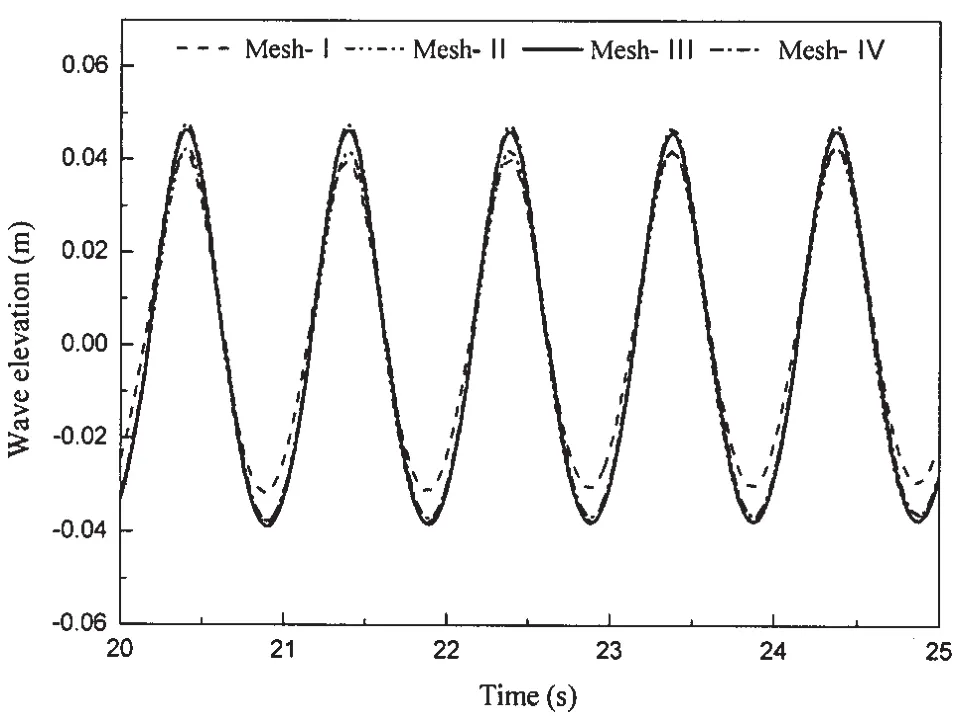
Three mesh models are adopted to find the efficient and accurate mesh model.A regular wave with height of 0.09 m and period of 1 s is selected as the target wave.Based on the linear dispersive relation,the wave length is L=1.56 m.The number of meshes within per wave height and length is used as one criterion to specify the meshing model.Four meshing models are designed:Mesh-I,Mesh-II,Mesh-III and Mesh-IV.There are about 8 meshes within per wave height and 50 meshes within per wave length in Mesh-I;13 meshes per wave height and 80 meshes per wave length in Mesh-II;20 meshes per wave height and 110 meshes per wave length in Mesh-III;25 meshes per wave height and 140 meshes per wave length in Mesh-IV. The detailed meshing information is listed in Tab.1.To reduce the number of elements and get a smooth free surface,structured grids were used in the domain;meanwhile,elements adjacent to the free surface were refined to improve accuracy.The overview of meshing model is shown in Fig.2.

Tab.1 The detailed information on meshing models

Fig.2 Mesh of the computational domain
2 Numerical results
2.1 Validation of Mesh Models
A series of gauges are located along wave tank(x=2 m,4 m,6 m,8 m,10 m,12 m,15 m).x=10 m is chosen as the target location.Considering the disturbances of the flap movement with full amplitude,the positions of x=8 m,x=10 m,x=12 m are chosen as the reference to test the efficiency of the meshing models.
The Fluent Implicit Unsteady solver was applied to carry out the transient computations. To ensure stability in time-marching,an acceptable time step should meet the requirement that a fluid particle should not cross more than a computational cell within a time step,i.e.with the Courant number C,the stability condition is:

where u is the particle velocity,Δt is the time step,Δl is the minimum cell size.
Airy-wave theory gives a reasonable analytical estimation for the maximum velocity components inside a wave as umax=ω0a= 0.28,the minimum cell size is near the static free surface which is Δlmin=0.003 5.In this study,all cases are calculated with the same time step 0.001 s(T/1 000)to ensure the Courant number is less than one.It can be seen from Figs.3~5 that Mesh-I is too coarse,Mesh-II shows an improvement, Mesh-III exhibits a great improvement to achieve the target wave.Compared with Mesh-III,the numerical results in Mesh-IV show little improvement,but require much more calculation resource.Therefore,Mesh-III is more suitable to conduct the numerical simulations in this study,compared with-Mesh-I,Mesh-II and Mesh-IV.

Fig.3 Wave elevation at the locations x=8 m for the four meshing models

Fig.4 Wave elevation at the location x=10 m for the four meshing models
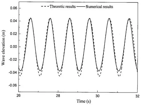
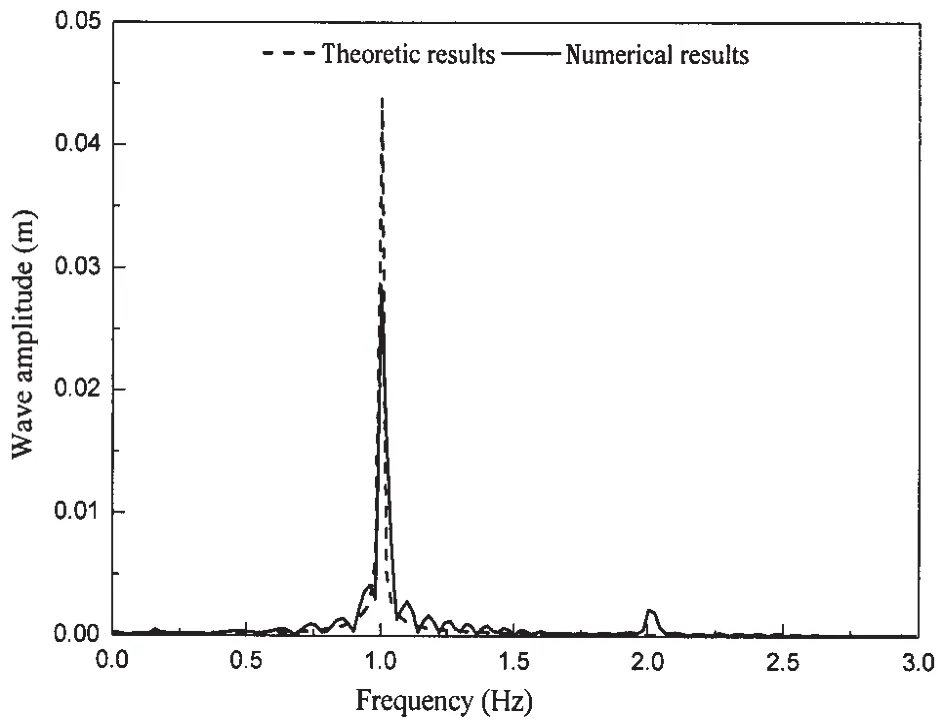
Fig.6 shows the comparison between the numerical results and the theoretical results.It can be seen in Fig.6 that the simulated wave crest is larger than that of wave trough.This asymmetry phenomenon is related to the nonlinearity of water waves due to high wave steepness.According to Ursell et al[16],wave steepness can be categrised into two groups:one is small wave steepness (0.002≤H/L≤0.03);the other is large wave steepness(0.045≤H/L≤0.048).Wave-wave interaction plays an important role during wave propagation and a second-order solution based on the sum of wave-wave interactions was identified by Longuet-Higgins and Stewart[19].The high-order wave components are embodied in the wave trains.Fig.7 shows the results of FFT spectrum uncovering the frequency spectrum of theoretic wave series and calculated wave series.Schäffer[20]introduced sec-ond-order wave generation theory which considered the wave-wave interaction components.Dalzell[12]gave a whole overview of second order wave theory which is described as follows:

where k is wave number,d is water depth, and ψ is expressed as follows:

Fig.8 shows the comparison of numerical results and the 2nd-order Stokes wave results.One can see from Fig.8 that the numerical results agree well with the 2nd-order Stokes wave results.Thus it is reliable to adopt 2nd-order Stokes wave theory to simulate waves considering sum frequency components.
2.2 Wave fade-in
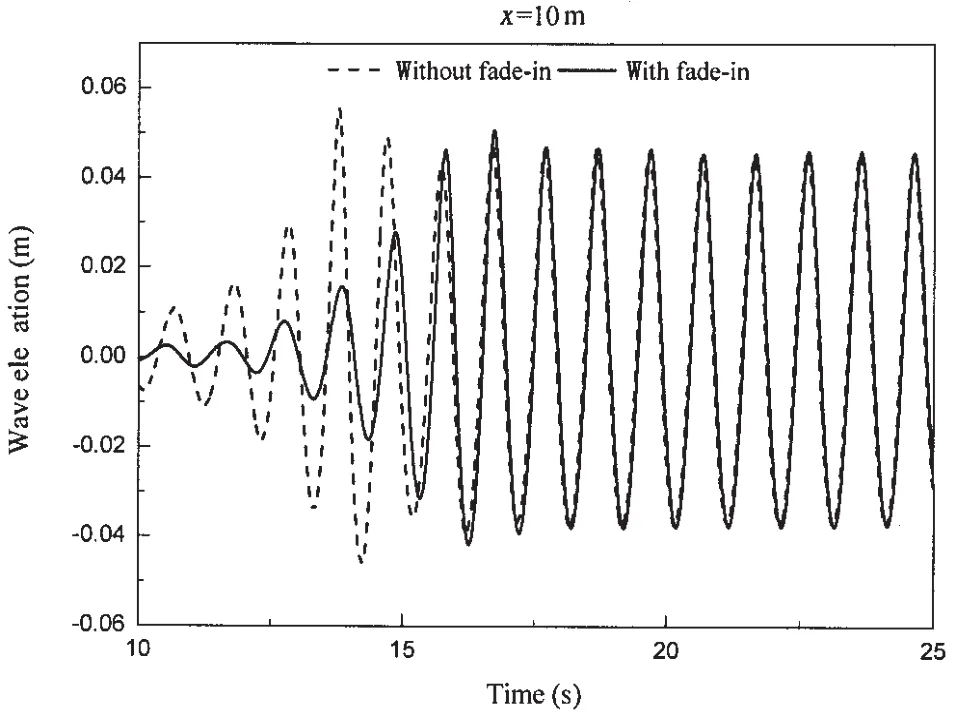
Using the traditional method,there will be obvious disturbance at the beginning period of wave generation.To avoid the disturbance,a fade-in method is adopted to make the wave-maker board reach maximum amplitude at the first 4 seconds afterstarting. Fig.9 presents an overview about the function of fade-in method.Wave height gradually reaches to the maximum wave amplitude.It can be seen in Fig.9 that there is little difference after the numerical simulation becomes stable.
2.3 Wave decay along wave tank

Fig.6 Comparison of numerical results and theoretical results

Fig.7 Frequency spectrum analysis of numerical and theoretic results

Fig.8 Comparison of numerical results and second-order Stokes results
With respect to the influence of grid size and time step,numerical dissipation is inevitable.Fig.10 illustrates attenuation along wave numerical tank.Hidenotes the wave height at the location of x=2 m,and x-axis represents thedistance away from the flap board.It can be noted that Mesh-I suffers serious wave damping along the numerical wave tank. However,Mesh-III shows much better results,compared with Mesh-I and Mesh-II. Although wave decay is smaller in Mesh-IV,it consumes too much calculation resource.
3 Conclusions

Fig.9 Comparison between numerical results with fade-in and without fade-in process
In this study,VOF method is used to capture the free surface in numerical wave tank.Four mesh conditions are tested to find out an efficient and reliable grid model.It is observed that 20 meshes per wave height and 120 meshes per wave length are sufficient enough for simulations of water waves. To avoid the disturbances at the beginning, a fade-in method is adopted.FFT spectrum method is used to check the high frequency components of the simulated wave train. The simulated wave agrees well with the second-order stokes results.At last,wave decay along numerical wave tank is investigated for the four meshing conditions.This study does not attend to provide a comprehensive understanding of strongly nonlinear waves,it is just aimed to serves as a basis for the future research regarding strongly nonlinear waves,such as the generation of freak waves.

Fig.10 Wave decay along Numerical Wave Tank
[1]Westphalen J,D Greaves,C J Williams,A Hunt-Raby,Zang Jun.Focused waves and wave-structure interaction in a numerical wave tank[J].Ocean Engineering,2012,45:9-21.
[2]Chappelear J E.Direct numerical calculation of nonlinear ocean waves[J].J Geophys,1961,70(18):4561-4572.
[3]Dean R.Stream function representation of nonlinear ocean waves[J].Journal of Geophysical Research,1965,70(18): 4561-4572.
[4]Zhang H,HASchäffer.Approximate Stream Function wavemaker theory for highly non-linear waves in wave flumes[J].O-cean Engineering,2007,34(8):1290-1302.
[5]Fenton J.The numerical solution of steady water wave problems[J].Computers&Geosciences,1988,14(3):357-368.
[6]Brorsen M,Larsen J.Source generation of nonlinear gravity waves with the boundary integral equation method[J].Coastal Engineering,1987,11(2):93-113.
[7]Zhao Xizeng,Sun Zhaochen,Hu Changhong.A numerical method for nonlinear water waves[J].Journal of Hydrodynamics, Ser.B,2009,21(3):401-407.
[8]Bai Wei,Eatock Taylor R.Numerical simulation of fully nonlinear regular and focused wave diffraction around a vertical cylinder using domain decomposition[J].Applied Ocean Research,2007,29(1):55-71.
[9]Kim M,Niedzwecki J,Roesset J.Fully nonlinear multidirectional waves by a 3-D viscous numerical wave tank[J].Journal of Offshore Mechanics and Arctic Engineering,2001,123(3):124-133.
[10]Clauss G F,Schmittner C E,Stück R.Numerical wave tank-simulation of extreme waves for the investigation of structural responses[C]//in Proc.,24th International Conference on Offshore Mechanics and Arctic Engineering.Greece,2005.
[11]Wang Y.Numerical wave channel with absorbing wave-maker[J].China Ocean Engineering,1995,9:149-160.
[12]Dalzell J.A note on finite depth second-order wave-wave interactions[J].Applied Ocean Research,1999,21(3):105-111.
[13]Mori N,Yasuda T.Effects of high-order nonlinear interactions on unidirectional wave trains[J].Ocean Engineering,2002, 29(10):1233-1245.
[14]Baldock T,Swan C,Taylor P.A laboratory study of nonlinear surface waves on water[J].Philosophical Transactions of the Royal Society of London.Series A:Mathematical,Physical and Engineering Sciences,1996,354(1707):649-676.
[15]Hirt C W,Nichols B D.Volume of fluid(VOF)method for the dynamics of free boundaries[J].Journal of Computational physics,1981,39(1):201-225.
[16]Ursell F,Dean R G,Yu Y.Forced small-amplitude water waves:A comparison of theory and experiment[J].Journal of Fluid Mechanics,1960,7(01):33-52.
[17]Finnegan W,Goggins J.Numerical simulation of linear water waves and wave-structure interaction[J].Ocean Engineering,2012,43:23-31.
[18]Liang Xiufeng,Yang Jianmin,Li Jun,Xiao Longfei,Li Xin.Numerical simulation of irregular wave-simulating irregular wave train[J].Journal of Hydrodynamics,Ser.B,2010,22(4):537-545.
[19]Longuet-Higgins M S,Stewart R.Changes in the form of short gravity waves on long waves and tidal currents[J].Journal of Fluid Mechanics,1960,8(04):565-583.
[20]Schäffer H A.Second-order wavemaker theory for irregular waves[J].Ocean Engineering,1996,23(1):47-88.
数值波浪序列中的高频成分
高宁波,杨建民,李 欣
(上海交通大学 海洋工程国家重点实验室,上海 200240)
可靠的波浪模拟方法对于海洋结构物水动力性能的评估而言至关重要。文章基于软件FLUENT,分别采用四种不同的网格模型,实现了对于规则波的模拟。文中采用VOF方法对自由液面进行捕捉,并采用动网格方法模拟摇板的运动从而实现造波。考虑到数值耗散及截断误差对数值模拟结果的影响,针对沿水池方向的波浪衰减情况进行了相关研究。为了避免造波板的初始运动所引起的波面扰动,引入了一种“缓入”方法使造波板缓慢地达到最大幅值的运动,有效地避免了初始扰动所带来的影响。数值模拟的结果分别与一阶和二阶理论解进行了对比。结果表明,该数值波浪模型能够给出可靠的预测,为下一步模拟强非线性波浪(如畸形波)奠定了基础。
流体体积;“缓入”方法;规则波;二阶波浪理论
O351
:A
国家自然科学基金重点项目(51239007)
高宁波(1988-),男,上海交通大学博士研究生;
O351
A
10.3969/j.issn.1007-7294.2016.06.002
1007-7294(2016)06-0655-09
杨建民(1958-),男,上海交通大学教授,博士生导师;
李 欣(1975-),女,上海交通大学副教授。
Received date:2015-12-11
Foundation item:Supported by the National Natural Science Foundation of China(Grant No.51239007)
Biography:GAO Ning-bo(1988-),male,Ph.D.candidate of Shanghai Jiao Tong University,E-mail: jiaxiang3708@sjtu.edu.cn;Corresponding author:YANG Jian-min(1958-),male,professor/tutor of Shanghai Jiao Tong University,E-mail:jmyang@sjtu.edu.cn.
猜你喜欢
杂志排行
船舶力学的其它文章
- Numerical Simulation of Hydrodynamics of Torsional Wave Propulsion in Stationary Water
- URANS Simulation on Diffraction Problem of a Vessel with Transom Stern
- Numerical Simulation of High Velocity Water Impact on the Rigid Plate by Discontinuous Galerkin Method
- Experimental Evaluation on a Newly Developed Dynamic Positioning Time Domain Simulation Program
- Prediction of Crack Growth Rates of a High Strength Titanium Alloy for Deep Sea Pressure Hull under Three Loading Patterns
- Fatigue Reliability Analyses Considering Short Crack and Dwell Time Effects
