Numerical Simulation of Hydrodynamics of Torsional Wave Propulsion in Stationary Water
2016-05-16,,,
,,,
(China Ship Scientific Research Center,Wuxi 214082,China)
Numerical Simulation of Hydrodynamics of Torsional Wave Propulsion in Stationary Water
BAI Ya-qiang,ZHANG Jun,ZHAI Shu-cheng,DING En-bao
(China Ship Scientific Research Center,Wuxi 214082,China)
The Gymnarchus Niloticus Fish(GNF)with long dorsal-fin generally cruises with high efficiency and extra-ordinal maneuverability while it can keep its body for the straight line.The unsteady flow field of torsinal wave propulsion is calculated using the dynamic grid technique including spring-based smoothing model and local grid remeshing,which is adaptable to the fin surface deforming significantly for torsional wave propulsion at stationary water.In the present numerical simulation,the maximum swing amplitude of fin ray reaches 85°.The numerical simulation result is compared with hydrodynamics experiments result.The pressure distribution on the fin surface and its variation with fin ray phase,and the relationship with thrust force production,the force fluctuation with wave frequency are analyzed.The results indicate that the thrust force coefficients do not vary with fin wave frequency.The frequency of surge force and heave force are both 2 times of wave frequency while the sway force frequency is the same as the wave frequency.
torsional wave;bionic propulsion;numerical simulation
0 Introduction
Combining the flexible streamlined body and unique propulsion mode,the fish gets more high propulsion efficiency and extra-ordinal maneuverability through its instinct control to absorb the energy of the eddy current.Therefore,the bionic propulsion is the one focus for propulsion research[1-2].The Gymnarchus Niloticus Fish(GNF)with long dorsal-fin torsional wave propulsion,generally swims with high efficiency while its body keeps for the straight line, it frequently reverses the movement direction with no need for turning only by changing the direction of the traveling wave of the fin,and isable to swift swim backward as itis swimming forward.
Due to the strong non-stationarity and nonlinearity of the three dimensional flow of torsional wave propulsion,it is difficult to seek out a theoretical solution based on the classic theory of potential flow.Experimental prototypes of torsional wave propulsion are designed and used to measure hydrodynamic forces and flow structure.In 2001(Sfakiotakis et al)parallel bellows actuator was used to imitate long flexible fin to explore the mechanism of torsionalwave propulsion[2].A variety of fin surface wave was generated by the bionic propulsion apparatus to produce positive and reverse thrust.
A long anal fin propulsion motor driven prototype was designed(Maclver et al,2003)to imitate the naked eel fish‘black ghost knife-fish’[3].Bionic fin robot with a pair of lateral wave fin propulsion was developed(Willy et al,2005)to imitate a stingray pectoral fin structure and movement[4].
In 2008,The flow field of torsional wave propulsion was computed using the immersed boundary technique to solve the Navier-Stokes equations(Shirgaonkar et al)for weakly electric knife-fish[5],to get surge,heave and sway force on fin surface.The maximum swing amplitude of fin ray is up to 30°.
In 2014,Amneet Pal Singh Bhalla et al developed an adaptive numerical method for fluid-structure interaction(FSI)problems about torsional wave propulsion,and efficiently captured thin boundary layers at fluid-solid interfaces as well as flow structures shed from such interfaces.In addition,this scheme was used to simulate free swimming,including the maneuvering of a three-dimensional model of the weakly electric black ghost knife-fish[6].
The swimming motion of a fish-like body with two undulating side fins similar to a Stingray and a Cuttlefish was investigated(Rahman et al,2010)by numerical simulation[7-8].A bodyfitted moving grid was generated numerically using the Poisson’s equation at each time step. The numerical computation was conducted for various aspect ratios,fin angles and frequencies, and the relationship was examined based on the distribution of pressure difference between upper and lower surface and the thrust force.The maximum swing amplitude of fin ray reaches 45°.
The braking performance of the undulating fin propulsion system of a biomimetic squidlike underwater robot was investigated(Rahman et al,2013)through free-run experiment and simulation of the quasi-steady mathematical model[9].The results indicate that the torsional wave propulsion system can effectively perform braking even in complex underwater operations.
The swing amplitudes of the above-mentioned prototypes of torsional wave propulsion is not larger than 45°.Based on dorsal fin of GNF,a torsional wave propeller was designed in which swing amplitude reaches 85°and the waveform is of high fidelity(Jiang et al,2012).The thrust force of dorsal fin was measured in stationary water[10].
According to a large number of observations,the swing amplitude of GNF(as shown in Fig.1)fins is between 60°to 90°, and in normal state of tour,the amplitude is close to 90°,only in the hovering control or swimming at very low speed,the amplitude is smaller(about 60°).
In this paper,numerical simulation is performed to the torsional wave propulsion of long dorsal fin to get the hydrodynamics in stationary water,the maximum swing amplitude of fin rayreaches 85°.Numerical results are compared with test results[10].The force fluctuation and its relationship with the wave frequency are studied.

Fig.1 Photo of Gymnarchus Niloticus Fish(GNF)
1 The numerical simulation of torsional wave propulsion
1.1 The equation of fin surface motion
The fin surface is fully unfolded during GNF swimming,the motion rule of the fin ray will directly determine the dynamic fin surface equation,GNF fin surface wave is of a typical torsional wave motion.In the paper,biomimetic fish fin movement takes fundamental frequency harmonic approximation,each ray rotates for sinusoidal oscillation based on ox axis:

where φmis swing amplitude of fin ray,ω is torsional wave frequency,k=2π/λ is wave number,λ is the wave length.φ0=-kx0is initial phase of fin ray at x0,which gradually lags along ox direction,c=ω/k is wave speed.XOY is longitudinal plane,also the symmetric plane of fin surface motion,the origin of coordinates is located in the wave fin front end.
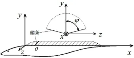
In cylindrical coordinate system(Fig.2),The GNF dorsal fin surface equation is as follows:


Fig.2 Schematic of long dorsal fin and coordinate system

Fig.3 Fin surface 3D configuration and three view drawing
Various GNF dorsal fin torsional wave model can be imitated by variation of φm,ω,k for different swingamplitude,wavefrequency and wave length.
1.2 Dynamic grid technique for simulation of flow field around fin surface with large deformation
The swing amplitude of each fin ray is large during GNF swimming,and swing angle changes with time(phase).In the numerical simulation,the swing amplitude can reach 85°.Dynamic grid technique(Fig.4)is applied to the fin surface deforming significantly.Grid update process is done automatically according to the variation of boundary in each iteration step.

Fig.4 Computational grid near fin surface
In this paper,the spring-based smoothing and local remeshing are applied during the grid dynamic change process.In spring-based smoothing model,thegrid side istreated as the spring connected between two nodes.According to Hoke’s law,the forces acting on the grid node can be written as follows:


At the new balance position,the resultant force acting on node i should be equal to zero, so the iteration equation is as follows:

After the boundary nodes position renews,the displacement of boundary nodes is obtained.The Jacobi method is used to solve the iteration equation and get the new position of internal nodes:

where n and n+1 represent the node position at present time step and the next,respectively.
Since the fin swing amplitude during torsional wave propulsion is very large,the distortion of the meshes around fin surface is serious.In the process of numerical simulation,the spring stiffness coefficient is continuously adjusted so that the fin grid deformation is quickly transferred out,to avoid the large distortion of grid around fin surface,and ensure the quality of the grids around fin surface.
Because of large deformation of the fin surface,the displacement of fin surface may be far greater than the neighboring grid size,then the spring-based smoothing model may lead to adecrease in the grid quality,even the negative value of grid volume appears,or the calculation could not be convergent as a result of mesh excessive distortion.In order to solve this problem,the local remeshing is performed to these grids with too large grid distortion rate or too intensive variation of grid size in the calculation process.
1.3 Validation of numerical simulation method
The numerical simulation results are compared with the experimental results(Jiang,2012). The parameter of prototype of torsional wave propulsion is as follows:dorsal fin height h= 45 mm,dorsal fin length L=800 mm,wave number L/λ=2,wave frequency f=2.0 Hz, swing amplitude φm=85°.

Tab.1 The comparison of thrust coefficients between numerical simulation and experiments
The comparison of thrust coefficient between numerical simulation and experiment results shows that there is relative bias of about 9.49%(Tab.1).Considering there is still some differences between the numerical and experiment test,such as the torsional wave propulsion apparatus is installed in the base of a cylinder with diameter 100 mm in the experiment while it is simplified as a baseline in the numerical simulation model,the above mentioned bias is acceptable.
2 Hydrodynamics of torsional wave proprlsion
As a case of numerical simulation,the geometric and movement parameters of torsional wave are as follows:wave numbers L/λ=2,wave frequency f=2.0 Hz,the height of fin ray h= 45 mm,the swing amplitude φm=75°.

Fig.5 Thrust force coefficient fluctation with time(phase)

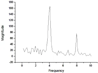
Fig.6 Frequncy-spectrum analysis of thrust coefficient fluctuating

Fig.7 Fluctuation of force components in three axial directions with time
Fig.5 shows thrust force coefficientof torsional wave propulsion varies over time (phase).WhereThe fluctuation of KTis obviously periodical.Fig.6 is the spectrum analysis diagram of KT.There is a significant peak at 4.0 Hz and secondary peak at 8.0 Hz,which is much smaller than the significant peak.It is obvious that thrust force frequency is 2 times of wave frequency.
Fig.7 shows the variation of dynamic force coefficient in different axial directions.We can draw some conclusions from the figure:(1)The thrust force(x-force)is much larger than the other two axial force;(2)The frequency of surge force(x-force)and heave force(y-force)is both 2 times of wave frequency while the sway force(z-force)frequency is the same as the wave frequency;(3)The mean magnitude of sway force(z-force)is zero which is consistent with the fin’s motion taking the XOY plane as plane of symmetry.

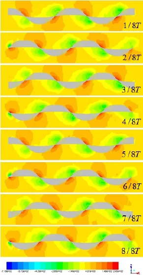
Fig.9 Pressure distribution on fin surface in a horizontal plane(y=45 mm)during one wave period

Fig.8 Pressure distribution on the fin surface in a horizontal plane

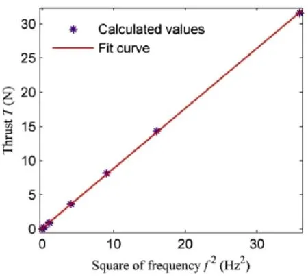
Fig.10 Mean thrust force T with respect to wave frequency(numerical simulation)
Fig.8 shows the pressure distribution around the fin surface in a horizontal slice of y=45 mm at certain moment.It is obvious that the pressure distribution is different on the two sides of the fin surface.The high pressure region(cyan in the color map)and low pressure region(green in the color map)appear at the different sides of the fin surface,respectively,resulting in a distinct pressure gap at the inflection point of the fin surface.Each of these pressure gaps will cause a hydrodynamic force normal to the fin surface which will induce a force parallel to the x-axis always in the same direction(the negative direction of the x-axis,i.e.the direction of thrust force).This explains the mechanism of the production of thrust force in the torsional wave propulsion.
Fig.9 shows the variation of pressure distribution on the fin surface during one wave period.As fin ray swings in the transverse plane,traveling wave spreads from left to right,also pushing the water from the left to the right.At the same time,the high and low pressure regions generate periodically on the fin’s positive and reverse sides,respectively,and travels from left to right with torsional wave.
Fig.10 shows the variation trend of mean thrust force T with wave frequency,it is obvious that mean thrust force T has a quadratic dependence with wave frequency,i.e.the coefficient KTdoes not vary with wave frequency.
3 Conclusions
The hydrodynamics of torsional wave propulsion imitating the long dorsal fin of Gymnarchus Niloticus Fish are studied in the paper.The dynamic grid technique including springbased smoothing and local grid remeshing is used for the torsional wave propulsion with large swing amplitude in the stationary water,in which the swing amplitude of fin ray reaches 85°.
The numerical simulation is validated by the experiment result.The pressure on fin surface presents periodic variation.While fin ray swings in the transverse plane,the torsional wave travels from left to right,and the high and low pressure region generates on positive and reverse sides,and thrust force is produced by the pressure gap.The results indicate that the frequency of surge force and heave force of wave propulsion is of 2 times of wave frequency, while sway force frequency is equal to wave frequency.The mean thrust coefficient KTdoes not vary with wave frequency.
[1]Wang Guangming,Hu Tianjiang,Li Fei,Shen Lincheng.Research on swimming by undulatory long dorsal fin propulsion [J].Chinese Journal of Mechanical Engineering,2006,42(3):88-92.
[2]Sfakiotakis M,Lane D M,Davies B C.An experimental undulating-fin device using the Parallel Bellows Actuator[C]// IEEE International Conference on Robotics and Automation.Seoul,Korea,2001:2356-2362.
[3]Maclver M A,Fontaine E,Burdick J W.Designing future underwater vehicles principles and mechanisms of the weakly electric fish[J].Journal of Oceanic Engineering,2004,29(3):651-659.
[4]Willy A,Low K H.Development and initial experiment of modular undulating fin for untethered biorobotic AUVs[C].The IEEE International Conference on Robotic and Biomimetics,2005:45-50.
[5]Shirgaonkar A A,Curet O M,Patankar N A,MacIver M A.The hydrodynamics of ribbon-fin propulsion during impulsive motion[J].Expt.Biol.,2008,211:3490-3503.
[6]Bhalla A P S,Bale R,Griffith B E,Patankar N A.A unified mathematical framework and an adaptive numerical method for fluid-structure interaction with rigid,deforming,and elastic bodies[J].Journal of Computational Physics,2013,250: 446-476.
[7]Rahman M M,Toda Y,Miki H.Study on the performance of the undulating side fins with various aspect ratios using computed flow,pressure field and hydrodynamic forces[C]//Proceedings of the 5th Asia-Pasific Workshop on Marine Hydrodynamics.Osaka,Japan,2010:333-338.
[8]Rahman M M,Toda Y,Miki H.Computational study on the fish-like underwater robot with two undulating side fins for various aspect ratios,fin angles and frequencies[C].Proceedings of MARTEC,2010:29-34.
[9]Rahman M M,Sugimori S,Miki H,Yamamoto R,Sanada Y,Toda Y.Braking performance of a biomimetic squid-like underwater robot[J].Journal of Bionic Engineering,2013,10:265-273.
[10]Du Defeng,Jiang Xiaoqin.Hydrodynamic forces measurement in still water tank and theoretical validation of a bio-dorsal fin propulsive system[J].Applied Mechanicsand Materials,2012,107(105):1980-1984.
静水中扭波推进水动力的数值模拟
白亚强,张 军,翟树成,丁恩宝
(中国船舶科学研究中心,江苏 无锡 214082)
尼罗河魔鬼鱼(GNF)采用长背鳍扭波推进,具有较高的推进效率和机动性,而鱼体主体可以保持直线不变形。为适应扭波推进过程中鳍面的大摆角变形,文中采用动网格技术求解了静水中扭波推进非定常流场,鳍面最大计算摆角达到85°,并通过与水动力实验结果比较验证了数值计算方法的可靠性。文中还分析了鳍面压力分布随相位的变化及其与推力产生的关系,以及水动力随扭波频率的脉动规律。研究表明,推力系数不随扭波频率而变化,轴向、垂向力波动频率是扭波频率的2倍,而侧向力脉动频率与扭波频率一致。
扭波;仿生推进; 数值计算
U664.3
:A
国家自然科学基金项目(51379193)
白亚强(1990-)男,中国船舶科学研究中心硕士研究生;
U664.3
:A
10.3969/j.issn.1007-7294.2016.06.001
1007-7294(2016)06-0647-08
张 军(1967-)男,中国船舶科学研究中心研究员;
翟树成(1986-)男,中国船舶科学研究中心工程师;
丁恩宝(1974-)男,中国船舶科学研究中心研究员。
Received date:2016-03-29
Foundation item:Supported by the National Natural Science Foundation of China(No.51379193)
Biography:BAI Ya-qiang(1991-),male,master degree candidate of China Ship Scientific Research Center;
ZHANG Jun(1967-),male,professor,Corresponding author,E-mail:zhangjuncssrc@163.com.
猜你喜欢
杂志排行
船舶力学的其它文章
- High-Frequency Components in Numerical Wave Trains
- URANS Simulation on Diffraction Problem of a Vessel with Transom Stern
- Numerical Simulation of High Velocity Water Impact on the Rigid Plate by Discontinuous Galerkin Method
- Experimental Evaluation on a Newly Developed Dynamic Positioning Time Domain Simulation Program
- Prediction of Crack Growth Rates of a High Strength Titanium Alloy for Deep Sea Pressure Hull under Three Loading Patterns
- Fatigue Reliability Analyses Considering Short Crack and Dwell Time Effects
