A Multi-Moment Finite Volume Method forIncompressible Navier-Stokes Equationson Unstructured Grids
2016-05-12BinXiePengJinFengXiao
Bin Xie, Peng Jin, Feng Xiao
(Department of Energy Science, Tokyo Institute of Technology, 226-8502, Japan)
A Multi-Moment Finite Volume Method forIncompressible Navier-Stokes Equationson Unstructured Grids
Bin Xie*, Peng Jin, Feng Xiao
(Department of Energy Science, Tokyo Institute of Technology, 226-8502, Japan)
A robust and accurate finite volume method (FVM) is proposed for incompressible viscous fluid dynamics on triangular and tetrahedral unstructured grids. Different from conventional FVM where the volume integrated average (VIA) value is the only computational variable, the present formulation treats both VIA and the point value (PV) as the computational variables which are updated at each time step. The VIA is computed from a finite volume scheme of flux form, and is thus numerically conservative. The PV is updated from the differential form of the governing equation that does not have to be conservative but can be solved in a very efficient way. Including PV as the additional variable enables us to make higher-order reconstructions over compact mesh stencil to improve the accuracy, and moreover, the resulting numerical model is more robust for unstructured grids. We present the numerical formulations in both two and three dimensions on triangular and tetrahedral mesh elements. Numerical results of several benchmark tests are also presented to verify the proposed numerical method as an accurate and robust solver for incompressible flows on unstructured grids.
Finite volume method, Unstructured grid, Robustness, Accuracy, Triangular/tetrahedral mesh, Incompressible flow, Multi-moment, Compact-stencil
0 Introduction
The finite volume method (FVM) has gained a great popularity in computational fluid dynamics (CFD) because of its better conservativeness and flexibility to adapt to both structured and unstructured grids. However, conventional FVM requires wide stencil to generate high-order reconstructions, and the choice of the cell stencil is not straightforward.
As mentioned in [1], particular attention must be paid to choose the admissible stencils and there is not a simple rule to guide this procedure for reconstructions higher than first order. As a matter of fact, most operational codes are limited to the second order on unstructured grids, where a linear reconstruction such as the MUSCL (Monotone Upstream-centered Schemes for Conservation Laws) scheme [2, 3] is used.
On the other hand, the majority of numerical methods for incompressible flows are essentially based on the pressure-correction (or pressure-projection) approach, even they appear in the literature as different variants, such as the projection method[4], MAC(Marker and Cell)[5] method, SIMPLE (Semi-Implicit Method for Pressure-Linked Equations) method[6], SIMPLEC(SIMPLE Corrected) method [7] and PISO(Pressure Implicit with Splitting Operators) method[8]. All these methods work very well under the second-order FVM framework where the velocity can be directly coupled with the pressure through a pressure-projection step when staggering or co-volume arrangement is adopted.
Although the second-order FVM on unstructured meshes proves itself a good trade-off between computational complexity and numerical accuracy, and has been widely accepted as a practical CFD framework for real-case applications, some remaining problems, for example the dependency of solution quality on computational mesh and the poor accuracy in advection computation, still deserve further efforts for more accurate and robust formulations. Some high-order DG methods have been devised for incompressible unsteady Navier-Stokes equations [9-12]. A common practice is to use the fractional-step pressure projection for the temporal updating and use DG for the spatial discretization, which is usually more complex and computationally expensive compared to the conventional FVM.
In this paper, we propose a novel numerical formulation to solve incompressible unsteady Navier-Stokes equations by including the point value (PV) of the velocity field at the cell vertices as a new DOF in addition to the volume integrated average (VIA) that is the only computational variable in the conventional FVM. The present method is called Volume integrated average and Point value based Multi-moment (VPM) method, in which the VIA moment is computed by a finite volume formulation of flux form, and thus exactly conservative, while the PV moment is updated by point-wise Riemann solver that can be computed very efficiently in unstructured grids. The reconstruction that is needed to evaluate the numerical fluxes and the derivatives in the spatial discretization is determined from the constraint conditions in terms of both VIA and PV as the computational variables. More precisely, we construct piecewise incomplete quadratic polynomials of 6 DOFs in 2 and 8 DOFs in 3 dimensions. In addition to one VIA and three (2D) or four (3D) PVs of a single grid cell, the derivatives at the cell center are also used to determine the polynomials. The derivatives are approximated from the VIA and PVs of the cells sharing the boundary edges with the target cell. The stencil is compact, and more importantly there is no arbitrariness in choosing the stencil for reconstruction. Compared to the conventional finite volume method, significant improvements in accuracy and robustness can be achieved by the present method without large increase in algorithmic complexity and computational cost.
The present formulation can be seen as an extension of the CIP multi-moment finite volume methods [13-22] to incompressible Navier-Stokes equations on unstructured grids with triangular and tetrahedral elements. The multi-moment finite volume methods have been developed on structured grids as accurate and robust fluid solvers and applied so far to various applications. The underlying idea to make use of multiple types of moments facilitates novel numerical models of greater efficiency and flexibility and is consequently much beneficial for implementations in unstructured grids.
1 Numerical Formulation on Unstructured Mesh
We consider the incompressible unsteady Navier-Stokes equations,
(1)

(2)
whereu=(u,v,w)isthevelocityvectorwithcomponentsu,vandwinx,yandzdirections respectively.pis the pressure,ρthe kinematic viscosity.
The projection method of Chorin [4] provides a simple and robust solution procedure for incompressible flow and is adopted in this paper. We briefly summarize the numerical steps to update the velocity from time levelm(t=tm)tom+1(t=tm+Δt)asfollows.
1)Giventhevelocityfieldumat step m, compute the intermediate velocityu*from the momentum Eq.(2) without the pressure gradient term,

(3)
2)Theintermediatevelocityu*usually does not satisfy the mass conservation Eq.(1), and must be corrected by the projection shown in the next step. For that purpose, we solve the pressure field at step (m+1) from the following Poisson equation,
(4)
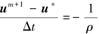
3)Correctthevelocitybytheprojectionstep,
(5)
Itisstraightforwardtoshowthattheupdatedvelocitysatisfies·um+1=0.
Ourmajorinterestinthispaperistodevelopanovelapproachforthespatialdiscretizationforthesolutionprocedureshownabove.
1.1 Computational Mesh
We firstly describe the numerical formulation in 2D by discarding the component inzdirection. The computational domain is divided into non-overlapping triangular cellsΩi(i=1,…,Ne)withthreeverticesθij(j=1,2,3)locatedat(xi1,yi1), (xi2,yi2)and(xi3,yi3)respectivelyasshowninFig.1(a).WealsodenotethemasscenterofΩibyθic.

(a)
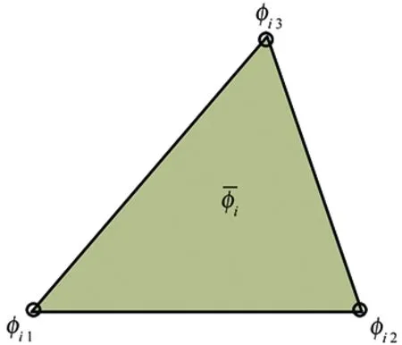
(b)Fig.1 Triangular mesh element (a) and the definition of discrete moments (b).

(6)
where |Ωi|denotesthevolumeofcellΩi.
Given both VIA and PV, a polynomial can be constructed in terms of VIA and PV. For simplicity, mesh cellΩiis mapped onto a standard element
(7)
We give some numerical formula to transform the first-order derivatives between the global coordinate system (x,y) and the local coordinate (ξ,η)
(8)
and
(9)
where |Ji(ξ,η)|=xξi(ξ,η)yηi(ξ,η)-xηi(ξ,η)yξi(ξ,η)isthedeterminantoftheJacobianmatrix.
Itisstraightforwardfrom(7)that
(10)
and
|Ji(ξ,η)|=2|Ωi|=(xi2-xi1)(yi3-yi1)-
(xi3-xi1)(yi2-yi1)
(11)
1.2 Multi-moment Reconstruction
The piecewise reconstruction polynomial for physical fieldφ(x,y) on cellΩiis written in the local coordinate system as,
Φi(ξ,η)=c00+c10ξ+c01η+c11ξη+c20ξ2+c02η2
(12)
Theunknowncoefficientsareuniquelydeterminedby
whichareobtainedfromthefollowingconstraintconditionsintermsofthemultiplemoments,
(14)

Interpolationfunction(12)canbeequivalentlycastintoabasisfunctionformas,

(15)
wherethebasisfunctionsread
(16)
whichareidenticalforallmeshcells.
Inthepresentmodel,bothVIAandPVaretreatedasthecomputationalvariablesandupdatedateverytimestepthroughthepressure-projectionsolutionprocedureshownabove.ItshouldbenotedthatinclusionofthePVsasnewcomputationalvariablescausesincreaseincomputationalcost.Forasinglephysicalvariable,wehavetomemorizeboththePVforeachvertexandVIAforeachgridcell.AnincreaseinCPUisalsoobserved.Allthesedependonthetopologyofthegridelements.Adetailedcomparisonwiththeconventionalfinitevolumemethodwillbeshownlater.Itrevealsthatthepresentmethodismoresuperiorregardingthecompromisebetweennumericalaccuracyandcomputationalcost.
Next,wediscussthespatialdiscreteschemesateachsub-stepindetails.
1.3 Scheme for Advection-diffusion Equation
The advection-diffusion equation in 2D is written in conservative form as
∂φ/∂t=-·(φu)+ν2φ
(17)
whereφis the physical quantity, which stands for eitheruorvin 2D Navier-Stokes equations. Remembering that all terms on the right hand side of (17) are known at each time level, we omit the superscriptmhereafter unless it is needed.
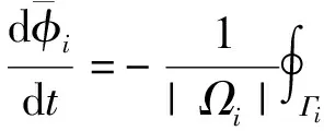
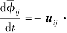
In the present method, two types of moments, i.e. the volume integrated average (VIA) and the point value (PV) of the physical fieldφ, are treated as the prognostic variables and updated separately. Their governing equations can be immediately obtained from definition (6) and (17), i.e.
(18)
forVIAmomentand
(19)
forPVmoment.NotethatwehaveusedGaussdivergencetheoremandassumedaconstantkinematicviscositytoyield(18).
Next,wedescribethespatialdiscretizationforthetermsontherighthandsidesof(18)and(19).
1.3.1AdvectionFlux
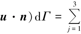
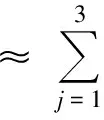
The total advection flux for cellΩiis approximated by the summation of those across each boundary segment,
(20)

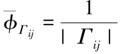
The line-integrated average ofφalong edgeΓijis not continuous and has different values for the two neighboring cells sharingΓij. We choose the upwinding side value according to the hyperbolic feature of the advection equation,
(21)
whereΦi updenotes the reconstruction function (12) or (15) over the upwinding cell, i.e.

(22)
ItshouldbenotedthattheSimpsonquadratureformulain(21)isexactforreconstruction(12)or(15).Toshowthis,wegiveexplicitlytheline-integratedaverageofΦialong edgeΓijas
(23)
1.3.2 Diffusion Flux
In a similar way, the total diffusion flux for cellΩiis approximated by the summation of those across each boundary edge,
∮Γi(n·φ)ij|
(24)

(25)
(26)
1.3.3GradientOperatorintheAdvectionTerm
The PV moment at the vertices (θij) of the triangular mesh elementΩi,φij(j=1,2,3), is predicted from the differential form equation (19), where the gradients of the advection terms are computed from a weighted upwinding scheme,
(27)
for derivative with respect to xand
(28)
forderivativewithrespecttoy.Here,Ωk(k=1,2,…,K)representtheunionofcellsthatsharevertexθij,andΦkthereconstructionfunctions(12)or(15)oncellΩk.TheweightΩkiscomputedby
(29)

1.3.4DiffusionOperator
We denote again byΩk(k=1,2,…,K) the union of cells that share vertex (θij). Given the net diffusion fluxes for these cells calculated by (24), the point wise value of the diffusion term atθijcan be simply obtained from the Time-evolution converting (TEC) formula described in [16, 19]. To be more precise, the time tendency of VIA in this case is computed by

(30)
whichisalreadyobtainedby(24).
ThetimetendencyofthePVduetotheLaplaceoperatoristhencomputedfromtheTECformulabasedontheleastsquareminimizationdescribedinappendixBin[23],whichyields
ν(2φ)ij=δtφij=TEC
(31)
1.3.5TimeIntegrationScheme
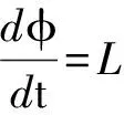
The semi discrete equations (18) and (19) are used to update the VIA and PV moments. We summarize these equations into a form of ordinary differential equation,
(32)
whereL(φ)standsforthespatialapproximationsdiscussedabove.
Giventhesolutionφmattimeleveltm,weusetheRunge-Kuttatimeintegrationschemestopredictthesolutionφ*fortheadvection-diffusionequation.BothsecondandthirdorderRunge-Kuttaschemescanbeused.ThethirdorderTVDRunge-Kuttatimeintegrationmethod[24]isappliedfortimeintegrationinthispaper.Wegivetheschemeasfollows.
(33)
whereΔt=tm+1-tmisthetimeintegrationinterval.
InthecontextofincompressibleNavier-Stokesequations,theaboveprocedureappliescomponent-wiselytogettheintermediatevelocityfieldu*.
1.4 Scheme for Pressure Poisson Equation
In the present formulation, we only use the VIA moment for pressure. The Poisson equation (4) is recast in an integral form.
(34)
Discretizing (34) over cell Ωiyields
(35)

Theunitvectorofrijisdenotedbyeij=(exij,eyij)=rij/|rij|.
ThelinearinterpolationfunctionovertwoneighboringcellsΩiandΩijisthenwritteninthefollowingform,
(36)

(37)
(38)
From(37)and(38),withsomealgebraicmanipulation,wehave
(39)
Following[25, 26],weconsideracorrectiontothenon-orthogonalityofthemesh.WedecomposethenormalvectorofedgeΓijasfollows,
(40)
wheren‖ijrepresentsavectorco-linearwithedgeΓij.Thepressuregradienttermin(35)isthensplitintotwoparts,i.e.theorthogonalpartandthenon-orthogonalcorrectionpart,
(41)
Asadoptedin(17),wecalculatetheorthogonalcomponentimplicitlyusingthevaluesatlevelm+1andthenon-orthogonalcorrectionexplicitlywiththevaluesatlevelm,
(42)
Thus,Poissonequation(35)forpressureisfinallywrittenas
(43)
where
and

1.5 Projection of the Velocity Field
As the final step of the solution procedure, the velocity field must be projected onto a divergence-free subset. From the pressure field computed above, we firstly calculate the pressure gradients over each boundary edge by

(44)
and

(45)
TheVIAofvelocitycomponentsarethenupdatedby,

(46)
and

(47)
GiventheincrementsofVIAfrom(46)and(47)ontheunionofcells(Ωk,k=1,2,…,K)thatsharevertex(θij),weupdatethePVsofvelocityattheverticesagainbythetime-evolutionconverting(TEC)formulainappendixBas

(48)
and

(49)
1.6 Summary of the Numerical Procedure
In order to allow the users to follow the algorithm easily, we summarize again the solution procedure as the following steps.


1.7 Extension of the Numerical Procedure
All the numerical procedures in 2D described above can be extended to 3D in a straightforward manner. Here, we only present the 3D multi-moment reconstruction for tetrahedral mesh element, presuming that the rest of the 3D formulation can be derived by analogizing the corresponding component in 2D.
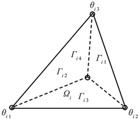
Fig.2 Tetrahedral mesh element for 3D.
We use the tetrahedral element for three dimensions. Shown in Fig. 2, cellΩi(i=1,…,Ne) has four verticesθij(j=1,2,3,4) located at (xi1, yi1), (xi2, yi2), (xi3, yi3)and(xi4,yi4).

Inasimilarway,thevolume-integratedaverage(VIA)andpoint-value(PV)attheverticesofaphysicalvariableφ(x,y,z,t)aredefinedas:
(50)
The3Dpiecewisereconstructionpolynomialforphysicalfieldφ(x,y,z)incellΩiinthelocalcoordinate(ξ,η,ζ)systemiscastintoabasisfunctionformintermsofmultiplemomentsas,
φi(ξ,η,ζ)=ψ1φi 1+ψ2φi 2+ψ3φi 3+ψ4φi 4+

(51)
whereφξi,φηiandφξiare the partial derivatives at the cell center, and the basis functions read
(52)

ψξ=ξ-η-ζ+ξη+ξζ+ηζ-ξ2+η2+ζ2
ψη=η-ξ+ζ+ξη+ξζ+ηζ+ξ2-η2+ζ2
ψξ=ζ-ξ-η+ξη+ξζ+ηζ+ξ-ζ2
Itisnotedthatthebasisfunction(52)aredeterminedfromthefollowingconstraintconditionsintermsofthemultiplemoments,

2 Numerical Results
We present some numerical tests to show the accuracy and robustness of the numerical method presented in this paper. In order to quantify the numerical errors, we defineL1andL2errors as follows,
(54)
and
(55)
where φniandφeidenotenumericalandexactsolutionsrespectively.
2.1 Advection of a Sine Wave
To evaluate the convergence rate of the advection scheme presented in section 1.3, we computed the advection transport of a sine function as in [27] with gradually refined grids. The advected profile is initially defined as
φ0(x,y)=sin2π(x+y)
(56)
overa[0,1]×[0,1]computationaldomain,theperiodicboundaryconditionisimposedinbothxandydirections.
Aconstantanduniformadvectionvelocityisspecified
u=1.0,v=1.0
(57)
NumericalexperimentswereconductedongraduallyrefinedgridsgeneratedbyDelaunayalgorithmwithdoublyincreasedresolution.ThetimestepofΔtisusedthroughoutallcomputations.

Table 1 Comparison of errors and convergence rates of different advection schemes
TheL1errors and the convergence rates of VPM and other standard schemes att=1.0 are given in Table 1 for grids of different resolutions.
It is observed that the presented scheme is of 3th order accuracy. Because the multi-moment reconstructions is of second order, the VIA is theoretically expected to be of third order accuracy, which is justified by the numerical output. Other standard schemes widely used for unstructured grids show convergence rates less than 2nd order, among which the QUICK scheme is more accurate for this smooth-profile test problem. Moreover, a comparison between the errors of VPM and standard schemes reveal a large improvement in numerical accuracy. On the grid of 57 518 elements, for example, theL1error of VPM is only 3% of the QUICK scheme.
2.2 Solid Rotation of a 2D Cone
It is well known that numerical solutions on unstructured grid depend on the quality of computational grid. In this test, we examine the robustness of the advection scheme to the quality of computational grid. A 2D cone of the initial distribution specified by
(58)
over [0,1]×[0,1] is transported with a rotational velocity field defined by u=-2π(y-0.5)andv=2π(x-0.5).
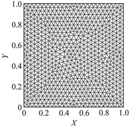
(a) Grid A: a mesh generated by Delaunay algorithm
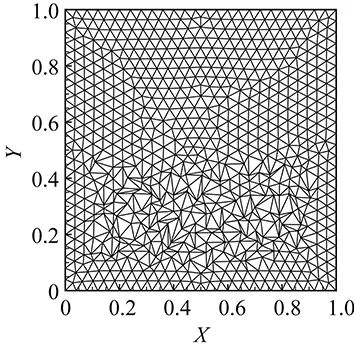
(b) Grid B: a mesh where a region has heavily distorted triangular elements with bas conditionin orthogonality, skewness and uniformityFig.3 Computational meshes for advection test.
Weusetwounstructuredgridswithtriangularelements.AsshowninFig.3,gridAisgeneratedbytheDelaunayalgorithmandhasgoodquality,whilegridBhasaregionwherethemeshelementsaredistortedwithlargeskewnessandhighaspectratio.ThenumericalresultsoftheVPMschemeafteronerevolutionofrotationareshowninFig.4.Itisfoundthatthedegradationinmeshqualitydoesn’tsignificantlyaffectthenumericalresults.

(a) Grid A
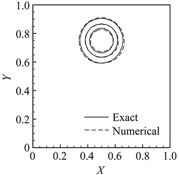
(b) Grid BFig.4 Numerical results of VPM scheme with the solid rotation advection tests on grid A and grid B.
(a) Grid A
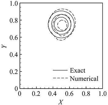
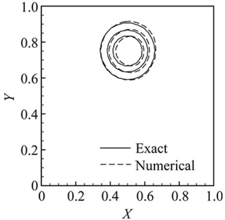
(b) Grid BFig.5 Same as Fig.4 but by the QUICK scheme.
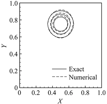
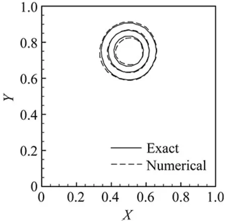
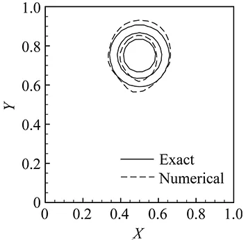
Forcomparison,wealsoincludethenumericalresultsfromotherstandardadvectionschemesusedinconventionalFVMcodes,suchastheQUICKscheme[28],Superbee-TVDscheme[29]andMUSCLscheme[2-3],whichareavailableintheOpenFoam[30]platform.Figs. 5, 6and7displaythecorrespondingoutputsoftheseschemesontwogrids.
(a) Grid A
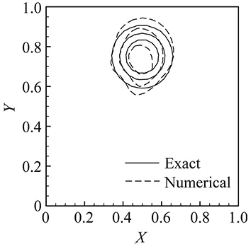
(b) Grid BFig.6 Same as Fig.4 but by the Superbee TVD scheme.
(a) Grid A
(b) Grid BFig.7 Same as Fig.4 but by the MUSCL scheme.
ComparedagainstFig.4,weobservethattheVPMschemeisthemostaccurateonbothgrids.Moreimportant,theconventionalschemesaremoresensitivetothemeshquality,whosenumericalresultslookremarkablyworseongridB.
Toquantifythisobservation,wegiveinTable2theL2errorsonbothAandBgridsforVPMmethodandotherstandardfinitevolumeschemeswiththe“degradationrate”definedby

(59)
As an indicator of the robustness to the computational grid, a smaller value of the degradation rate shows a better robustness in respect to the quality of mesh elements.
We can see that having the smallest degradation rate, the VPM scheme is the most robust one with regard to the computational grid, and thus retains the numerical accuracy even on a grid of worse quality. It is very sensible if we consider that in the present scheme both the cell average and vertex value are updated, which compensates the loss of the information due to the worse nonorthogonality and skewness of the mesh.
2.3 Taylor Vortex Problem
To evaluate the accuracy of the whole incompressible fluid solver, we computed the Taylor vortex problem [9, 11]. An analytical solution for this problem isavailable as
(60)
(61)
( 62 )
where ReisReynoldsnumber.WeuseRe=100inthisexample.
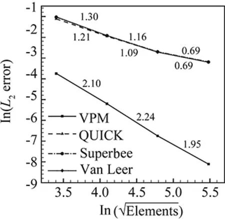
Wecomputedthistestproblemover[0,1]×[0,1]domainwiththeperiodicalboundarycondition,usinggridsofdifferentresolutions.Ourinteresthereistoevaluatethenumericalaccuracyinspatialdiscretization,andarelativelysmalltimesteppingincrement(Δt=10-4)isused.Weshowthenumericalerrorsandconvergenceratesforbothvelocityandpressurefieldsatt=0.1inTable3andFig.8.WealsoincludetheresultsoftheconventionalfinitevolumemethodwiththeQUICK,Superbee-TVDandMUSCLschemesastheadvectionsolvers.ItshouldbenotedthattheconventionalFVMmodelwasgeneratedbymergingthetemplatesprovidedbytheOpenFOAMsourcecodeintotheprojectionsolutionprocedureshowninsection1.
ItisobservedthattheVPMmethodismoreaccuratethantheconventionalFVMmodelsregardingbothnumericalerrorsandconvergencerate.NumericalsolutioninvelocityofVPMshowsaconvergenceratehigher2.5.Intheresultsontherefinedmesh(57 670cells),duetothehighconvergenceratethenumericalerrorsofVPMmodelinbothvelocityandpressurearereduceddowntoonly1%ofthoseintheconventionalFVMmodels.Itisalsofoundthattheerrorsinvelocityareapproximatelyone-tenthofthoseinpressureinallresults.
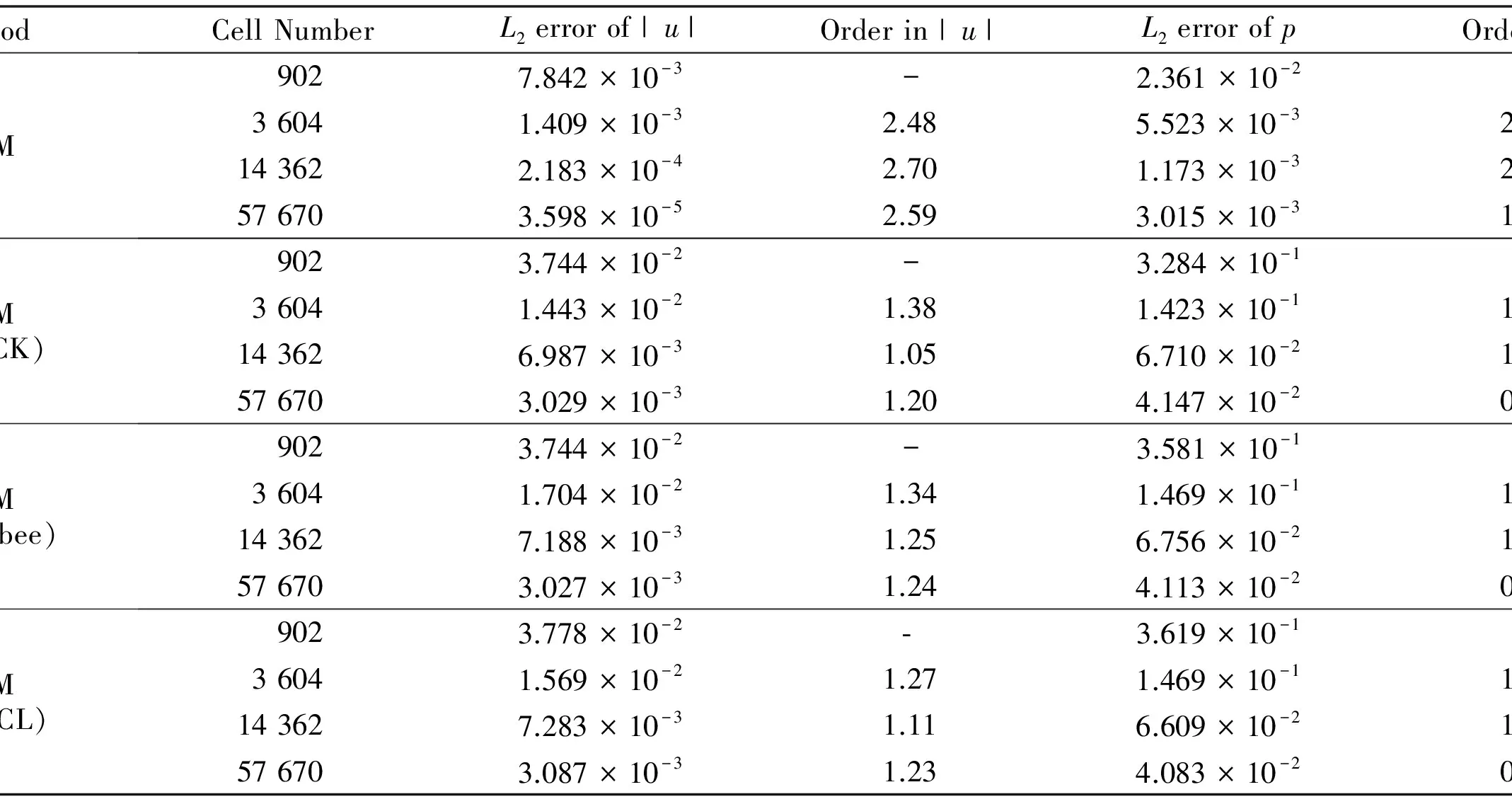
Table 3 Numerical errors on different grids and degradation rate

(a) Velocity
(b) PressureFig.8 Numerical errors and convergence rates for velocity and pressure.
2.4 Remarks on Computational Cost
Using both VIA and PV as the computational variables causes an increase in memory requirement. For a single physical field, we need to keep the PVs at the element vertices as the new degrees of freedom (DOFs) in addition to the VIAs as in the conventional FVM. It also leads to an increase in CPU consumption.
In order to quantify the computational cost in comparison with the conventional FVM, we run the 2D advection test with different grid resolutions for 1000 steps on a PC with a single CPU (Intel(R) Xeon E5-2687W, 3.10 GHz). We give in Table 4 the DOFs for the memory requirement and elapse time for CPU consumption. It is observed that for the triangular mesh the number of DOFs increases about 51%. As described before, the spatial discretization can be computed by firstly finding and saving the numerical fluxes and the derivatives from the multi-moment reconstructions for all cells, and then updating VIA cell-wisely and PV point-wisely. It is noted that the PVs at cell vertices are readily for use in the calculation of the numerical fluxes, which simplifies the operations and saves CPU time. Shown in Table 4, the elapse time increase may reach 1.5 fold
in comparison with the QUICK scheme. As shown in section 2.1, large improvement can be obtained by VPM scheme. From Table 1, we see that the numerical error of VPM on a 5 463-element grid is smaller than that of the QUICK scheme on a 14 412-element grid. It leads to an observation that for a given error level the VPM scheme is much more efficient in terms of both memory requirement and CPU consumption compared to the standard schemes due to its high accuracy and faster convergence.
The computational cost of the full fluid solver is also evaluated using Taylor vortex test shown above. About 34% increase is seen in the memory requirement due the fact that we only use the VIA for pressure field. The increase in elapse time varies with grid resolution, which is smaller for a coarse grid and becomes larger toward a saturation value of 42% when the number of grid cells is larger than 104. The increase in CPU consumption of the whole fluid solver is less significant than that of the pure advection computation. This result is consistent with the well-known observation that the pressure Poisson equation consumes the large part of CPU time.
It is observed that the numerical errors of VPM can be smaller than the conventional FVM by two orders of magnitude. Similar to the advection case, we can conclude that the VPM model is much superior in computational efficiency and requires much less hardware resource to reach a given error level in comparison with conventional FVM model. This justifies the practical utility of the VPM method.
2.5 Lid Driven Cavity Flows with Different Shapes
Incompressible viscous flows in closed cavities under the forcing of the upper lid moving at a constant speed provide a benchmark test set to verify numerical solvers. Following the standard test of Ghia et al.
[31], other tests of different geometric configurations were suggested as well to evaluate the capability of numerical codes to deal with complex geometries. We show next the results of the VPM model for four cavities of different shapes, i.e. square, forward-step duct, skewed rectangle and semi-circle. The Reynolds number used in the following four test cases is 1000.
2.5.1 Lid Driven Square Cavity Problem


Table 4 Computational cost estimation for advection calculation of VPM in comparison with the QUICK scheme
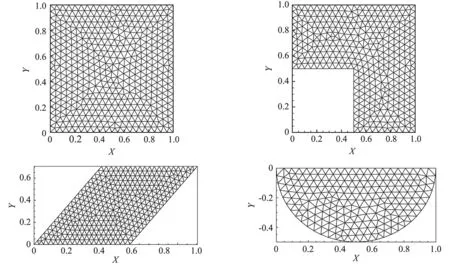
Fig.9 Geometrical configurations and computational meshes for 2D incompressible flow benchmark tests.

(a) u profile along x=0.5 line
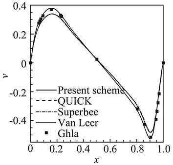
(b) v profile along y=0.5 line
2.5.2 Lid Driven Square Cavity Problem
A cavity with a forward-step shown in the upper-right panel of Fig.9 is used in [32] to evaluate numerical solvers developed in general coordinates. Numerical results are given in Fig.12 with the reference velocity profiles provided in [32] which were computed on a 512×512 curvilinear grids. Shown in Fig.12 (b)-(c), the present model is able to reproduce adequate solutions even with much coarser mesh resolutions. The solutions on meshes of more than 2 704 cells agree well with the reference solution.
2.5.3 Lid Driven Skew Cavity Problem
Numerical example of viscous flow in skew cavities with inclined angles of 30° is found in [33] and [32]. Our numerical results are shown in Fig.13. The reference solution in [33] is computed on 320×320 structured grids. Our numerical solution converges to the reference solution with much coarser grids compared to other existing conventional FVM schemes.
2.5.4 Lid Driven Semi-circular Cavity Problem
We computed the lid-driven viscous incompressible flow in a semi-circular cavity (bottom-right panel of Fig.9) which has been extensively investigated in [34]. We use the results in [34] for comparison which were computed on a triangular mesh with a representative size of 1/128. Shown in Fig.14, our results converge to the reference results even with a relatively low mesh resolution.

Fig.12 Numerical results of forward-step cavity flow problem. Displayed are streamline on a 7538-cell mesh (a),the u profile along x=0.75 line (b) and v profile along y=0.75 line (c).

Fig.13 Numerical results of a 30° inclined skew cavity flow problem. Displayed are streamline on a 1872-cell mesh (a),u profile along y=tan(30°)(x-0.5) line (b) and v profile along y=tan(30°/2) line (c).

Fig.14 Numerical results of semi-circular cavity flow problem. Displayed are streamline on a 2266-cell mesh (a),u profile along x=0.5 line (b) and v profile along y=-0.25 line (c).
2.6 3D Lid Driven Cubic Cavity Problem
As a verification of the 3D code, we simulated a 3D lid driven flow in a unit cube[-0.5,0.5]×[-0.5,0.5]×[-0.5,0.5]. Following [35], we imposed a constant velocityv(-0.5,y,z)=1 on surfacex=-0.5 and computed this test using tetrahedral grids of different resolutions. The velocity component inydirection (v) along centerline (x,0,0) and that inxdirection (u) along centerline (0,y,0) are plotted in Fig.15. For comparison, we also include the numerical results in [35] as a reference solution which are solved by a Chebyshev-collocation method with 96×96×64 Gauss-Lobatto points. It is seen that the present solver converges quickly to the reference solution.
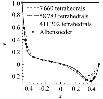
(a) u profile
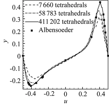
(b) v profileFig.15 Numerical results of 3D lid driven cubic cavity. Displayed are u profile along centerline (x,0,0) (a) and v profile along centerline (0,y,0) (b). The reference results of [35] was computed by Chebyshev-collocation method with 96×96×96 Gauss-Labatto points.
3 Conclusion Remarks
We have presented and evaluated a novel numerical solver forincompressible Navier-Stokes equations on triangular and tetrahedral unstructured meshes by using the multi-moment finite volume formulation. The numerical method, so-called VPM, treats the point value (PV) at the cell vertex as a new computational variable in addition to the volume integrated average (VIA) value that is the only computational variable in the conventional finite volume method. VIA is solved via a finite volume formulation of flux form, and is thus numerically conserved. PV is computed point-wisely based on the differential form of the governing equations which need not to be numerically conservative but can be solved efficiently. The numerical formulation can be very easily implemented on unstructured grids. With multiple moments, more DOFs can be used for each grid cell and high order reconstruction can be built on a compact stencil to calculate the numerical flux and derivatives for spatial discretization, which appears to be particularly important to unstructured grids. Another advantage of the present method is that there is not any arbitrariness in choosing the neighboring cells for the reconstructions.
As shown in this paper, when applied to incompressible fluid dynamics, VPM model causes about 30%-40% increase in the memory requirement and 40%-50% increase in CPU time. Nevertheless, a large leap in improving numerical accuracy and robustness is achieved. Our numerical results show that the numerical errors of VPM can be smaller than the conventional FVM by two orders of magnitude. The numerical experiments reveal that the numerical results of the present method converge to the reference solutions even with the relatively coarse grid resolutions. Consequently, the VPM model is much superior in computational efficiency and requires much less computer resource to reach a given error level in comparison with conventional FVM models. Moreover, the numerical solutions of the VPM model are less dependent on the quality of computational grids. All these justify the practicability of the VPM method in real-case applications.
The present formulation uses only cell average and point values at cell vertices as the unknown DOFs for triangular (2D) and tetrahedral (3D) elements. We have also applied the same idea to unstructured grids with other elements, such as quadrilateral (2D) and hexahedral (3D) elements, and obtained very promising results, which will be reported soon.
Higher order formulations for unstructured grids with other types of moments need further exploration. Given the DG formulation as a standard track, how to balance the algorithmic cost and the solution quality, which is always problem-dependent, should be a key in future practices. To sum up, with a modest increase in computational complexity and cost, the present VPM method is able to achieve significant improvements in accuracy and robustness in comparison with conventional finite volume method. Thus, it provides a practical solver for incompressible viscous flows which well balances the numerical accuracy and computational complexity.
[1]Friedrich O. Weighted essentially non-oscillatory schemes for the interpolation of mean values on unstructured grids[J]. J. Comput. Phys. 1998, 144: 194-212.
[2]Van Leer B. Towards the ultimate conservative difference scheme. IV: A new approach to numerical convection[J]. J. Comput. Phys., 1977, 23: 276-299.
[3]Van Leer B. Towards the ultimate conservative difference scheme, V: A second order sequel to Godunov’s method[J]. J. Comp. Phys., 1979, 32: 101-136.
[4]Chorin A J. Numerical Solution of the Navier-Stokes equations[J]. Math. Comp., 1968, 22: 745-762.
[5]Harlow F H, Welch J E. Numerical calculation of time-dependent viscous incompressible flow of fluid with a free surface[J]. Physics of Fluids, 1965, 8: 2182-2189.
[6]Patankar S V, Spalding D B. A calculation procedure for heat and mass transfer in three-dimensional parabolic flows[J]. Int. J. Heat and Mass Transfer, 1972, 15: 1787-1806.
[7]Van Doormaal J P, Raithby G D. Enhancements of the SIMPLE method for predicting incompressible fluid flows[J]. Num. Heat Transfer, 1984, 7: 147-163.
[8]Issa R I. Solution of implicitly discretized fluid flow equations by operator splitting[J]. J. Comput. Phys., 1986, 62: 40-65.
[9]Shahbazi K, Fischer P, Ethier C. A high-order discontinuous Galerkin method for the unsteady incompressible Navier-Stokes equations[J]. J. Comput. Phys., 2007, 222: 391-407.
[10]Hesthanven J, Warburton T. Nodal discontinuous Galerkin Methods[M]. Springer, 2008.
[11]Ferrer E, Willden R. A high order discontinuous Galerkin finite element solver for the incompressible Navier-Stokes equations[J]. Comput. and Fluids, 2011, 46: 224-230.
[12]Steinmoeller D T, Stastna M, Lamb K G. A short note on the discontinuous Galerkin discretization of the pressure projection operator in incompressible flow[J]. J. Comput. Phys., 2013, 251: 480-486.
[13]Yabe T, Aoki T. A universal solver for hyperbolic-equations by cubic-polynomial interpolation. 1. One-dimensional solver[J]. Comput. Phys. Commun., 1991, 66: 219-232.
[14]Yabe T, Xiao F, Utsumi T. The constrained interpolation profile method for multiphase analysis[J]. J. Comput. Phys., 2001, 169: 556-593.
[15]Xiao F, Yabe T. Completely conservative and oscillation-less semi-Lagrangian schemes for advection transportation[J]. J. Comput. Phys, 2001, 170 : 498-522.
[16]Xiao F. Unified formulation for compressible and incom-pressible flows by using multi integrated moment method: one-dimensional inviscid compressible flow[J]. J. Comput. Phys., 2004, 195: 629-654.
[17]Xiao F, Ikebata A, Hasegawa T. Numerical simulations of free-interface fluids by a multi integrated moment method[J]. Comput. Struct., 2005, 83: 409-423.
[18]Ii S, Shimuta M, Xiao F. A 4th-order and single-cell-based advection scheme on unstructured grids using multi-moments[J]. Comput. Phys. Comm., 2005, 173: 17-33.
[19]Xiao F, Akoh R, Ii S. Unified formulation for compressible and incompressible flows by using multi-integrated moments II: Multi-dimensional version for compressible and incom-pressible flows[J]. J. Comput. Phys., 2006, 213: 31-56.
[20]Ii S, Xiao F. CIP/multi-moment finite volume method for Euler equations: A semi-Lagrangian characteristic formulation[J]. J. Comput. Phys., 2007, 222: 849-871.
[21]Akoh R, Ii S, Xiao F. A CIP/multi-moment finite volume method for shallow water equations with source terms[J]. Int. J. Numer. Method in Fluid, 2008, 56: 2245-2270.
[22]Chen C G, Xiao F. Shallow water model on spherical-cubic grid by multi-moment finite volume method[J]. J. Comput. Phys., 2008, 227: 5019-5044.
[23]Xie B, Ii S, Ikebata A, et al. A multi-moment finite volume method for incompressible Navier-Stokes equations on unstructured grids: Volume-average/point-value formulation [J]. Journal of Computational Physics, 2014, 277: 138-162.
[24]Shu C -W. Total-variation-diminishing time discretizations[J]. SIAM J. Sci. Stat. Comput., 1988, 9: 1073-1084.
[25]Rossi R. Direct numerical simulation of scalar transport using unstructured finite-volume schemes[J]. J. Comput. Phys., 2009, 229: 1639-1657.
[26]Juretic' F, Gosman A D. Error analysis of the finite-volume method with respect to mesh type[J]. Numerical Heat Transfer, Part B: Fundamentals, 2010, 57(6): 414-439.
[27]Hu C, Shu C -W. Weighted essentially non-oscillatory schemes on triangular meshes[J]. J. Comput. Phys., 1999, 150: 97-127.
[28]Leonard B P. A stable and accurate convective modelling procedure based on quadratic upstream interpolation[J]. Comput. Methods Appl. Mech. Eng., 1979, 19: 59-98.
[29]Roe P L. Some contributions to the modeling of discontinuous flows[R]. Springer Verlag: Lectures in Applied Mathematics, 1985, 22: 163-193.
[30]Jasak H. OpenFOAM: Open source CFD in research and industry[J]. Int. J. Naval Archit. and Ocean engin., 2009, 1: 89 -94.
[31]Ghia U, Ghia K N, Shin C T. High-Re solutions for incompressible flow using the Navier-Stokes equations and a multigrid method[J]. J. Comp. Phys., 1982, 48: 387-411.
[32]Oosterlee C W, Wesseling P, Brakkee E. Benchmark solutions for the incompressible Navier-Stokes equations in general co-ordinates on staggered grids[J]. Int. J. Numer. Method in Fluid, 1993, 17: 301-321.
[33]Demirdži I, Lilek Ž, Peri M. Fluid flow and heat transfer test problems for non-orthogonal grids: Bench-mark solutions [J]. International Journal for Numerical Methods in Fluids, 1992, 15(3): 329-354.
[34]Glowinski R, Guidoboni G, Pan T W. Wall-driven incompressible viscous flow in a two-dimensional semi-circular cavity[J]. J. Comput. Phys., 2006, 216: 76-91.
[35]Albensoeder S, Kuhlmann H C. Accurate three-dimensional lid-driven cavity flow[J]. J. Comp. Phys., 2005, 206: 536-558.
0258-1825(2016)02-0252-15
基于非结构网格的不可压N-S方程多矩有限体积法
Bin Xie*, Peng Jin, Feng Xiao
(Department of Energy Science, Tokyo Institute of Technology, 226-8502, Japan)
提出了一种基于三角形及四面体非结构网格的有限体积法(FVM),用以鲁棒且精确地求解不可压粘性流动问题。与传统的FVM方法仅将体积分平均值(VIA)作为计算变量的做法不同,本文提出的方法将VIA及点值(PV)同时作为计算变量并在每个迭代步进行计算更新。VIA以通量形式进行计算以确保数值守恒,PV可以通过控制方程的不同形式进行求解更新,无需守恒,因此可以采用非常高效的方法进行求解。将PV作为增加的变量使得紧致网格模板得以实现更高阶精度的重构,而且由此获得的数值模型对于非结构网格变得更鲁棒。本文针对二维/三维的三角形/四面体非结构网格提出了数值格式,给出了几个基准测试算例,验证了本文提出的数值方法在采用非结构网格求解不可压粘性流动问题时的精确性和鲁棒性。
有限体积法; 非结构网格; 鲁棒性; 精度; 三角形/四面体网格; 不可压流动;多矩; 紧致模板
V211.3
A doi: 10.7638/kqdlxxb-2016.0013
*JSPS Researcher, Department of Energy Science; Xie.aa@m.titech.ac.jp
format: Xie B, Jin P, Xiao F. A multi-moment finite volume method for incompressible Navier-Stokes equations on unstructured grids[J]. Acta Aerodynamica Sinica, 2016, 34(2): 252-266.
10.7638/kqdlxxb-2016.0013. Xie B, Jin P, Xiao F. 基于非结构网格的不可压N-S方程多矩有限体积法(英文)[J]. 空气动力学学报, 2016, 34(2): 252-266.
Received date: 2015-12-15; Revised date:2016-02-10
猜你喜欢
杂志排行
空气动力学学报的其它文章
- Simulation of Aerial Refueling System withMultibody Dynamics and CFD
- Validation of HyperFLOW inSubsonic and Transonic Flow
- A Detached Eddy Simulation Model forFree Surface Flows
- Numerical Modeling and Prediction of the Effectof Cooling Drag on the Total Vehicle Drag
- Numerical Simulation of Large Scale Structures andCompressibility Effect in Compressible Mixing Layerswith a Discontinuous Galerkin Method
- Residual Schemes Applied to an Embedded MethodExpressed on Unstructured Adapted Grids
