Pressure Oscillating Flow in Corrugated Parallel Channel∗
2016-05-09YuFeiWei魏育飞HaiJunWang王海钧andYongJunJian菅永军
Yu-Fei Wei(魏育飞),Hai-Jun Wang(王海钧),and Yong-Jun Jian(菅永军),
1Department of Physiology,Hetao College,Bayannur 015000,China
2Mathematical Science College,Inner Mongolia Normal University,Hohhot 010022,China
3School of Mathematical Sciences,Inner Mongolia University,Hohhot 010021,China
1 Introduction
Oscillating flow can be found in engineering,such as ocean engineering,environmental engineering,thermal engineering,and bio-engineering.[1−2]Oscillating flow can be induced by the oscillation of the wall in which the fluid flows,[3−8]the oscillation of pressure gradient,[9]and the other external force.[10]Zheng et al.[11]researched the unsteady rotating flow of a generalized Maxwell fluid with fractional derivative model between two in finite straight circular cylinders,where the oscillating flow was reduced to the oscillating pressure gradient.The dynamics of pressure and temperature fluctuations occurring in flow boiling in a minichannel,which consisted of the heated section and glass condenser were experimentally investigated and modeled by Grzybowski and Mosdorf.[12]Manos et al.[13]presented the analytical solution of the equations of motion for a fully developed laminar flow in a curved channel with circular walls,when an oscillating circumferential pressure gradient was imposed.The combination of oscillating gradient waveforms with single-point imaging techniques to perform measurements of rapidly oscillating and/or rotating fluid motion was demonstrated.[14]Nam and Jeong[15]developed a model for the oscillating flow combined with pulsating pressure in cryocooler regenerators,which overcame the inaccuracy of the conventional flow model based on steady flow friction factor.In our article,the fluid in the channel is driven by the oscillating pressure.Nadeem and Maraj[16]investigated the peristaltic flow of hyperbolic tangent fluid in a curved channel analytically with the help of homotopy perturbation method.
All the aforementioned papers are concerned with smooth channel.However,the roughness always exists on the surface of channel walls generally.Tay[17]et al.presented an experimental investigation of adverse pressure gradient turbulent flow over two rough surfaces and a reference smooth surface.Tsikata and Tachie[18−19]presented the studies of turbulent flows over smooth and rough walls in a channel driven by an adverse pressure gradient(APG) flow experimentally.The researches involved are all about the experimentally study.By utilizing perturbation method,Si and Jian[20]solved analytically the problem of the Jeffrey fluid flow in the parallel microchannel with corrugated walls,driving by Lorenz force.Moreover,Buren and Jian et al.[21−22]studied analytically the Newtonian fluid flow in the parallel rough microchannel driven by pressure and Lorenz force.To the authors’knowledge,there is no an article about the analytical solution on the fluid flow in the roughness channel driven by oscillating pressure gradient.
In this article,we study the Newtonian fluid flow in the corrugated channel driven by oscillating pressure gradient using the perturbation method.The corrugated channel wall can be described as periodic sinusoidal waves with small amplitude either in phase or half-period out of phase.The velocity and the mean velocity have been solved by utilizing perturbation method,and the in fluence of dimensionless parameters on them has been discussed graphically.
2 Formulation of the Problem
In this study,we research the vibration velocity of Newtonian flow in parallel channel whose distance is 2H with wavy walls,which is driven by the time periodical vibrating pressure gradient.Here a Cartesian coordinate system is adopted with the origin fixed at the middle of the channel.It is assumed the channel width W in y∗-axis and length L in the x∗-axis are assumed to be in finite,thus we discuss a 1D flow problem in this study.The upper and the lower wavy walls are located at

respectively.The corrugations of the two walls are periodic sinusoidal waves with wave number k∗and small amplitude ε(ε≪ 1)either in phase Eq.(1a)or half-period out of phase Eq.(1b),as shown in Fig.1.Assuming that=(u∗,v∗,w∗)is the velocities in x∗,y∗,z∗-directions respectively.The continuative and momentum equations of incompressible Newtonian fluid are written as

where ρ is the density of the fluid,µ is viscosity coefficient.The flow is in the x∗-direction.In this discussion we assume the velocities

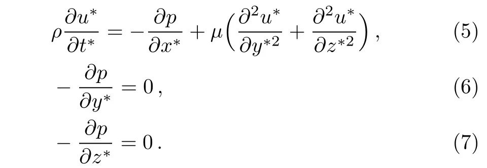
Thus,combining Eqs.(2)and(4),the momentum equations in x∗,y∗,z∗-directions can be rewritten as respectively

From Eqs.(6)and(7),we get that the pressure p is not the function of y∗and z∗,but the function of x∗and t∗,i.e.p=p(x∗,t∗).According to Eq.(1),the corresponding boundary conditions of u∗are as follows

Assuming that the pressure gradient in x∗-direction is time periodical,

and the velocity in x∗-direction has the form as


Introducing the non-dimensional parameter as follows

Substitution Eq.(13)into Eqs.(8),(9),and(12),the dimensionless momentum equation and its boundary conditions give

here Re is the oscillating Reynolds number and a measure of frequency in the oscillating pressure gradient field.In order to solve the velocity field in x-direction,we utilize the perturbation method.We applied ε in Eq.(1)as the small parameter due to it is very small,thus the velocity can be expanded as

Substituting Eq.(17)into Eq.(14)and dividing the order of ε,we get three functions of y and z:

Inserting Eq.(17)into the boundary conditions(15)and(16),and expanding Eqs.(15)and(16)in Taylor series at z=±1,i.e.


From Eqs.(21a)and(21b),the boundary conditions of Eqs.(18),(19),and(20)are given as the following expression respectively

Combing Eq.(18)and Eq.(22),the solution of zero-order has the form

Inserting Eq.(25)into Eq.(23),the boundary conditions of one-order function can be rewritten as

Due to the form of Eq.(26),we can suppose solution form of u1as follows

Substitution Eq.(27)into Eqs.(19)and(26),the function f(z)and its boundary conditions are given

From Eqs.(28)and(29),the solution of Eq.(28)is

So

Inserting Eqs.(25)and(31)into Eq.(24),the boundary conditions ofcan be expressed

Assuming that the second-order solution has the form as

Inserting Eq.(33)into Eq.(20)and Eq.(24),we get the functions and their boundary conditions of g(z)and h(z),respectively


Solving Eq.(33)and Eq.(35),

From Eq.(37),Eq.(38),and Eq.(32),we get the second-order solution

Finally,from Eq.(24),Eq.(30)and Eq.(39),the approximate velocity is

The volume flow rate per unit width of channel is found by

Firstly inserting(41)into(42),then expanding the integrated results in Taylor series regarded to the variable z and neglecting the third order term O(ε3),the volume flow rate can be expressed as finally

On average over one wavelength[0,2π/k]of corrugations,the mean velocity is defined as

Substituting(41)into(44)and using(42)and(43),the mean velocity has the form of


where The u0mdenotes the mean velocity when the walls are perfectly smooth,and φ±represents the leading-orderperturbations to the mean velocity due to the corrugations.The mean velocity increases when φ±is positive,while the mean velocity decreases when φ±is negative.
3 Results and Discussions
In the previous sections,approximate analytic solutions are obtained for the velocity,volume flow rate and the mean velocity o between parallel planes with corrugated walls.They depend greatly on several parameters defined above.
For fluidic analysis,half height of the channel is H∼1 cm,the domain conditions have been set with the physical properties of water of density ρ ∼ 103kg/m3,viscosityµ∼ 10−3kg/(ms).In addition,frequency of gradient pressure O(ω)ranges from 0–12 s−1.[23]Therefore,the order of Reynolds number O(Re)is changed from 0 to 1200 from Re= ρH2ω/µ.Moreover,the range of wave number k is considered as 0–10.Finally,amplitudes A of oscillating pressure gradient changes from 0 to 10.In the following calculations,the in fluences of parameters A,Re and k on PHD velocity and volume flow rates are investigated,and all these graphical results are obtained by using MATLAB program according to the expressions(41),(43)and(46).Specifically in this article,we set the small parameter ε as ε=0.1,because the too little parameter ε reduces the unobvious effect of wavy channel on the velocity and the average velocity.

Fig.1 Schematic diagram of parallel flow in corrugated channel.

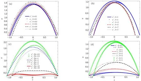
Fig.2 The in fluence of k,Re and A on u± with z(−1−ε−1+ε)when y=0.5π,ε =0.1.(a)In fluence of k(0.1,0.3,0.9)on u± when Re=1,A=4;(b)In fluence of k(1,3,7)on u± when Re=2,A=4;(c)In fluence of Re(0.1,1,5,10)on u± when A=4,k=1;(d)In fluence of A(0.5,1,2,5)on u± when Re=2,k=1.
In Fig.2 we plot the in fluence of the dimensionless parameters on velocities both in phase and out of phase.The shape of the channel a ff ects the velocity,and the velocity becomes larger with the increase of the width of the channel.Moreover,the velocity increases with the distance from the wall.When the channel walls are in phase,the walls are symmetrical about center;when the walls are out of phase,the walls are symmetrical,and so is the velocity in the channel,which can be seen from the variation of u−in Fig.2.Figures 2(a)and 2(b)show the effect of wave number k on velocities.From Fig.2(a)when k<1,we can see that the velocity u+decreases with k in the lower part of channel(−1−ε

Fig.3 The in fluence of k and A on u± with Re(0–15)when z=0,y=0.5π,ε=0.1.(a)In fluence of k(1,3,9)on u±when A=1;(b)In fluence of A(0.1,0.5,1,5)on u±when k=1.

Fig.4 (a)In fluence of k(0.3,0.8,2,4)on φ± with Re(0–3);(b)In fluence of Re(0.1,0.5,1,5)on φ± with k(0–5).
Figure 3 shows the effect of wave number k and amplitude A on velocities with Reynolds number Re.In Figs.3(a)and 3(b),we can find that when Re is large enough,the velocities are almost zero due to the effect of oscillation of pressure gradient.In Fig.3(a),the conclusion can be drawn that the velocities and the shifts of the velocities decrease with k.Figure 3(b)depicts the variation of velocity with Re for different A.with the increasing A,the velocities and the shifts of velocities both in phase and out of phase increase.
In Fig.4,the in fluence of k on mean velocity parameter φ±with Re and in fluence of Re with k are depicted.From Fig.4(a),we can find that increasing with Re,the roughness does not in fluenced on the mean velocity.With k,the mean velocity parameter φ±reduce,and it is same to the difference of φ±.In addition,when k=4,there is no difference between the φ±.Moreover,from Fig.4(b)we can get that when k>4,the difference is zero no matter what Re is,i.e.when the wave number k is large enough,the roughness does not effect on the velocity.
4 Conclusions
In this paper,we utilize the small parameter method to solve the problem of Newtonian fluid through the corrugated channel,where the shape of the rough perturbation inside the wall is sinusoidal.From the analysis above,we can get the conclusions:the velocity u±depend on the shape of the channel and the distance from the chan-nel.The velocity increases with the width of the channel.The velocities both in phase and out of phase increase monotonously with the increasing amplitude A of pressure gradient.Due to the oscillating effect,the velocity decreases with increasing Reynolds number Re.When the wave number k is large enough,the roughness does not effect on the velocity.With increasing Re,the φ±decrease,that is to say,when Re is large enough,the corrugation of the walls does not a ff ect the distribution of the velocity.
[1]J.Deng,X.Shao,and A.Ren,J.Hydrodyn.19(2007)751.
[2]B.Liang,H.Li,and D.Lee,J.Hydrodyn.20(2008)88.
[3]X.X.Peng,J.Hydrodyn.20(2008)770.
[4]M.R.Jovanović,Phys.Fluids 20(2008)11.
[5]A.M.Thomas,G.K.Thich,and R.Narayanan,Chem.Eng.Sci.61(2006)6047.
[6]T.Hayat,S.Nadeem,A.M.Siddiqui,and S.Asghar,Appl.Math.Lett.17(2004)609.
[7]N.Mudassar,Z.Muhammad,S.A.Muhammad,and A.Muhammad,Commun.Nonlinear Sci.17(2012)3219.
[8]M.Khan,S.H.Ali,and H.Qi,Math.Comput.Model.49(2009)1519.
[9]O.Jensen and M.Heil,J.Fluid Mech.481(2003)235.
[10]N.Takashi,S.Yoji,U.Mutsumi,and K.Nobuyuki,J.Wind Eng.Ind.Aerod.91(2003)199.
[11]L.Zheng,C.Li,X.Zhang,and Y.Gao,Comput.Math.Appl.62(2011)1105.
[12]H.Grzybowski and R.Mosdorf,Int.J.Heat Mass Tran.73(2014)500.
[13]T.Manos,G.Marinakis,and S.Tsangaris,J.Non-Newtonian Fluid Mech.135(2006)8.
[14]I.V.Mastikhin,N.L.Hetherington,and R.Emms,J.Magn.Reson.214(2012)189.
[15]N.Kwanwoo and J.Sangkwon,Cryogenics 45(2005)368.
[16]S.Nadeem and E.N.Maraj,Commun.Theor.Phys.59(2013)729.
[17]G.F.K.Tay,D.C.S.Kuhn,and M.F.Tachie,Int.J.Heat Fluid Fl.30(2009)249.
[18]J.M.Tsikata and M.F.Tachie,Int.J.Heat Fluid Fl.44(2013)239.
[19]J.M.Tsikata and M.F.Tachie,Int.J.Heat Fluid Fl.39(2013)127.
[20]D.Si and Y.Jian,J.Phys.D:Appl.Phys.48(2015)085501.
[21]M.Buren,Y.Jian,and L.Chang,J.Phys.D:Appl.Phys.47(2014)425501.
[22]M.Buren and Y.Jian,Electrophoresis 36(2015)1539.
[23]X.Ye and J.Zhang,Chin.J.Appl.Mech.20(2003)43.
杂志排行
Communications in Theoretical Physics的其它文章
- Quantum Private Comparison of Equality Based on Five-Particle Cluster State∗
- Weibel Instability Growth Rate in Magnetized Plasmas with Quasi-Relativistic Distribution Function
- Physiological Flow of Jeffrey Six Constant Fluid Model due to Ciliary Motion
- Free Convective Nonaligned Non-Newtonian Flow with Non-linear Thermal Radiation
- Dilepton from Passage of Jets Through Spherical Expanding QGP∗
- The Role of a1(1260)in π−p →(1260)p and π−p → π−ρ0p Reactions Near Threshold∗
