冲击加载下样品软回收过程中的侧向稀疏效应*
2016-04-18胡秋实李克武宋振飞
胡秋实,赵 锋,李克武,傅 华,宋振飞
(中国工程物理研究院流体物理研究所冲击波物理与爆轰物理重点实验室,四川 绵阳 621999)
冲击加载下样品软回收过程中的侧向稀疏效应*
胡秋实,赵 锋,李克武,傅 华,宋振飞
(中国工程物理研究院流体物理研究所冲击波物理与爆轰物理重点实验室,四川 绵阳 621999)
通过数值模拟,计算冲击加载下样品经历一维应变加载过程和侧向稀疏过程产生的塑性功, 给出试样内部从冲击加载开始到进入回收桶前全过程的应力随时间变化的历程。结果表明:侧向稀疏过程开始后,样品在径向汇聚波的作用下受循环拉、压载荷作用,拉压循环的振幅在中等冲击压力下达到最大。如果振幅超过了材料的层裂强度,样品中心将发生拉伸破坏不能完整回收。侧向稀疏与一维应变加载产生的塑性功之比随冲击速度的增加而减小。在冲击速度为某临界值时,侧向稀疏产生的塑性功与一维应变加载产生的塑性功相等。在一定的冲击速度下,采用低初始屈服应力的材料可减轻侧向稀疏效应。对理想塑性材料的理论分析表明,侧向稀疏与一维应变加载产生的塑性功之比随冲击速度与屈服强度比值的增大而减小,与数值模拟结果一致。
固体力学;侧向稀疏;残余应变;塑性功;冲击加载;软回收
冲击加载下的软回收实验是研究材料动态力学性能的重要途径。通过对回收试样的金相分析(如X射线衍射、透射电子显微镜和电子背散射衍射等),可得到材料的微结构信息,如点阵结构、位错密度、晶粒取向等,从而提高对冲击过程的认识。一个有效的软回收装置要求样品主要受到一维应变加载的影响而不是侧向稀疏的影响。为减轻侧向稀疏效应,W.F.Hartman[1]提出在样品周围加上保护环, 后来的一些回收实验也采用了这样的结构[2-3], 如图1(a)所示。为降低样品的动能,G.T.Gray III等[4]提出在样品右侧增加层裂板,如图1 (b)所示。

图1 软回收装置示意图Fig.1 Schematics diagram of two types of soft recovery assembly
飞片撞击样品产生的压缩脉冲进入层裂板后,遇自由面反射拉伸脉冲发生层裂,释放了冲击产生的能量,保证样品以低速进入回收桶,防止了样品高速进入回收桶可能产生的二次损伤[5-10]。图1所示的2种结构通过在样品周围增加保护环减轻了侧向稀疏效应,但减轻的效果如何却少见报道。A.L.Stevens等[11]指出 ,虽然保护环吸收了侧向稀疏波的能量,但样品卸载后侧向应力并不为零,因此当保护环同样品分离后,新的侧向稀疏效应(径向汇聚波)依然存在,从而对样品内的应力状态、残余应变等产生影响,但关于该影响的大小如何却少见报道。A.L.Stevens等[11]同时指出,影响材料残余效应的因素是塑性功而不是冲击压力或者残余应变,因此准确计算样品内部的塑性功有重要意义。
本文中,基于LS-DYNA有限元软件,对图1(b)装置中样品的冲击响应过程进行数值模拟。给出装置内部应力分布及样品中心处从冲击加载开始到进入回收桶前全过程的应力随时间变化的关系,计算样品内部一维应变加载过程和侧向稀疏过程产生的塑性功。
1 计算模型
采用图1(b)结构进行计算, 其中试样厚度为3 mm, 半径为11 mm, 保护环内径为11 mm, 外径为20 mm, 层裂板厚度为5 mm。单元类型为轴对称Lagrange单元,接触条件采用面面接触。飞片、试样、保护环和层裂板材料同为6061-T6 Al, 采用Grüneisen状态方程和各向同性硬化本构模型。材料参数为:密度ρ0=2.7 g/cm3, 剪切模量G=27.6 GPa, 屈服强度Y0=295 MPa, 硬化模量Ep=1.58 GPa, Grüneisen系数γ=2.1,c0=5.37 km/s,s=1.34[11-12]。
2 计算结果
2.1 试样内部应力状态和应力时间关系
图2给出了冲击压力为2.4 GPa,冲击速度为300 m/s时不同时刻样品内部的径向应力状态。从图2(a)看出,飞片撞击盖板产生的压缩脉冲在t=0.8 μs时进入样品,此时侧向稀疏波在保护环中传播不会对样品造成影响。经过0.8 μs后,压缩脉冲完全进入层裂板,如图2(b)所示。随后,该脉冲将遇自由面反射拉伸脉冲,使层裂板发生层裂,如图3所示。此外,t=0.8 μs压缩脉冲波尾和侧向稀疏波相遇后在交界处形成负压区(或拉伸区)[13],该负压区随着时间的推移而逐渐扩大,在t=1.6 μs进入保护环,为后续保护环和样品的分离提供驱动力。
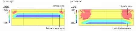
图2 冲击压力为2.4 GPa时样品内部不同时刻的径向应力状态Fig.2 Radial stress state of specimen under an impact pressure of 2.4 GPa at different times

图3 层裂后的应力状态Fig.3 Stress state after spallation
从图3中可以看出,发生层裂后层裂板分裂成2个层裂片,冲击产生的能量一部分用于形成层裂面(转化成表面能),另一部分转化成了2个层裂片的动能。计算中采用最大拉伸应力断裂准则,材料层裂强度为1.2 GPa,比热容为875 J/(kg·K)。

图4 样品、层裂片的速度时程曲线Fig.4 Velocity histories of specimen and spall plate
图4给出了样品和2个层裂片的速度时间历史。从图4中可以看出,样品在一维应变加载脉冲过后速度趋近于零,冲击产生的能量被2个层裂片带走。另外,样品在冲击加载后处于高温状态,因此回收时需要对样品进行快速降温才能将微结构固定下来,常用的降温材料(如油、水、液氮等)波阻抗都较高,如果样品以100 m/s或km/s量级的高速撞击这些材料势必会造成二次损伤[6],导致微结构的进一步改变,这样对回收样品进行金相分析得到的微观结构就不是仅由冲击加载引起,给后续分析造成困难。由此可见,保证样品低速进入回收桶是十分重要的。图5~6给出了冲击压力为2.4 GPa时6061-T6Al样品在一维应变加载脉冲下的纵向应力应变和纵向应力径向应力曲线。

(1)
(2)
(3)


图5 冲击压力为2.4 GPa时样品的纵向应力纵向应变关系Fig.5 Relationship between longitudinal stress and longitudinal strain under an impact pressure of 2.4 GPa

图6 冲击压力为2.4 GPa时样品的纵向应力径向应力关系Fig.6 Relationship between longitudinal stress and radial stress under an impact pressure of 2.4 GPa
从图6可以看出,状态4样品内的纵向应力σz=0但径向应力σr≠0,因此当保护环在拉应力的作用下(图2(b)中所示拉伸区)同样品分离后,将形成径向汇聚波向样品中心传播,使样品在随后的过程中处在拉压交替的状态。图7给出了冲击压力为2.4 GPa时6061-T6 Al样品中心处应力随时间变化的关系。
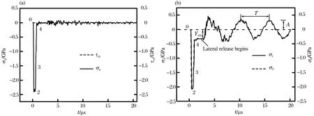
图7 冲击压力为2.4 GPa时样品中心处应力时程曲线Fig.7 Histories of stress at the axis of the specimen under an impact pressure of 2.4 GPa


图8 不同冲击压力下样品中心处有效应力时程曲线Fig.8 Histories of effective stress at the axis of the specimen under different impact pressures
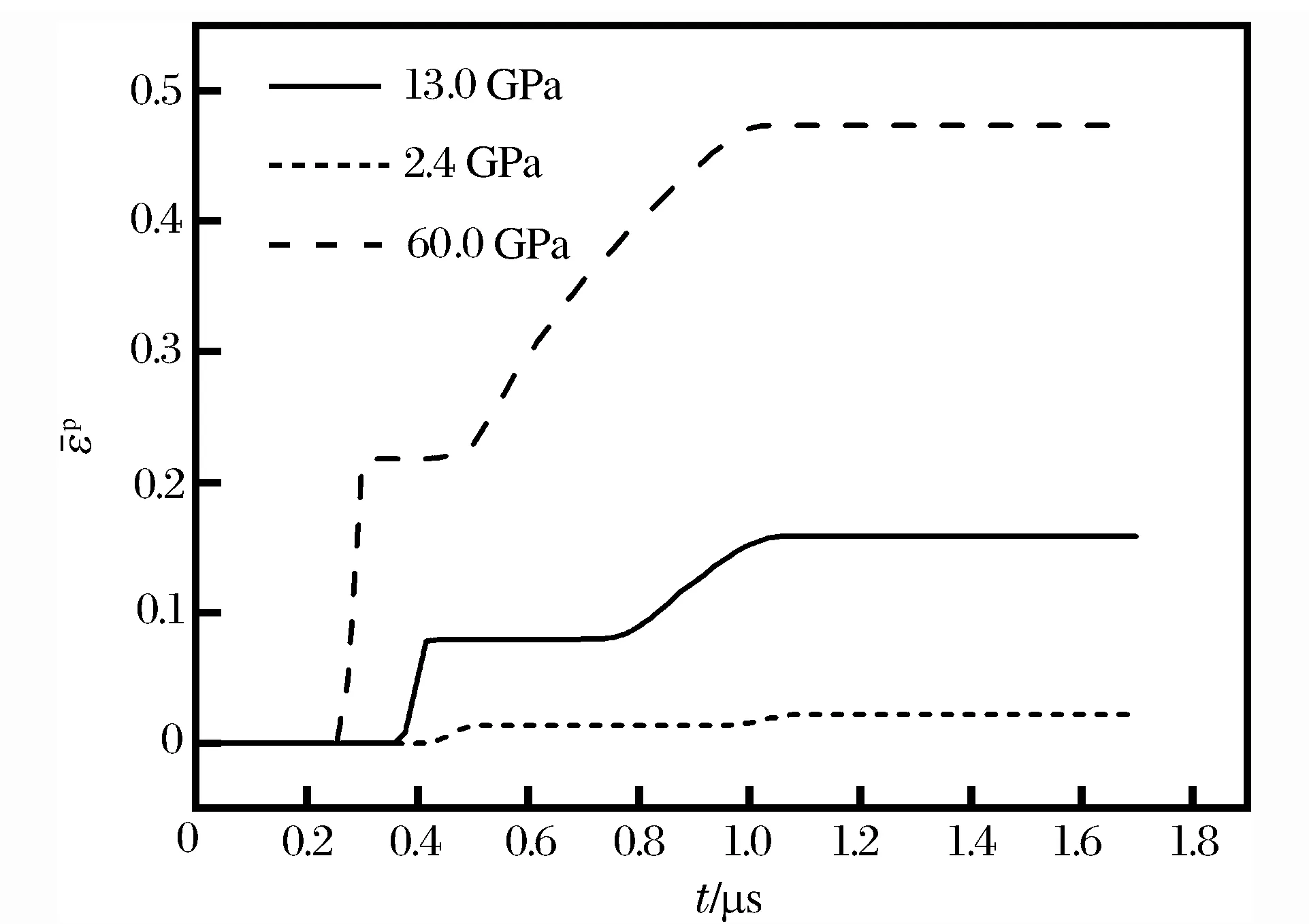
图9 不同冲击压力下样品中心处等效塑性应变时程曲线Fig.9 Histories of effective plastic strain at the axis of the specimen under different impact pressures
从图8~9可以看出,3种冲击压力下有效应力和等效塑性应变在t=1.6 μs后不再改变,说明此时一维应变加载过程已经结束而侧向稀疏过程还未开始,此时样品处于状态4,见图5~7。从图8可以看出,Y1D在冲击压力为13.0 GPa时达到最大,为0.36 GPa;在冲击压力为2.4 GPa时为0.32 GPa;而在冲击压力为60.0 GPa时由于温度软化效应使Y1D达到最小,为0.24 GPa。A.Molinari等[18]指出,冲击压力为9.0 GPa时6061-T6 Al的温升仅70 K,因此,在冲击压力较低时(2.0~13.0 GPa)应变硬化占主导,Y1D随冲击压力的升高而升高。从图9中看出,冲击压力在60.0 GPa时等效塑性应变达到了0.47,远远高于冲击压力为2.4 GPa时的0.022,但冲击压力为60.0 GPa时的Y1D却低于冲击压力为2.4 GPa时的Y1D(0.24 GPa<0.32 GPa),因此在冲击压力较高时(13.0~60.0 GPa),温度软化占主导,Y1D随冲击压力的升高而降低。在后续的侧向稀疏过程中,由于拉压循环的振幅A和Y1D近似相等,因此中等冲击压力将导致大的振幅。值得注意的是,如果振幅超过了材料的层裂强度,在拉压循环过程中将导致样品中心发生拉伸破坏不能完整回收。
2.2 一维应变加载和侧向稀疏产生的塑性功
长久以来,学者们试图将冲击加载下的残余效应归结为一维应变加载过程(包括冲击压力、压缩脉冲持续时间等)的影响[19]。塑性变形的本质是原子的重组(包括位错的运动、孪晶的形成等等),原子脱离平衡位置所需激活能源自塑性功,等效塑性应变的变化可以反映塑性功的变化。图10~11给出了冲击压力为2.4 GPa时6061-T6 Al样品中心处径向应力、等效塑性应变随时间的变化关系。

图10 冲击压力2.4 GPa时样品中心径向应力时程曲线Fig.10 Histories of radial stress at the axis of the specimen under an impact pressure of 2.4 GPa

图11 冲击压力2.4 GPa时样品中心等效塑性应变时程曲线Fig.11 Histories of effective plastic strain at the axis of the specimen under an impact pressure of 2.4 GPa

(4)
(5)
由于侧向稀疏过程开始后,样品中心处的纵向应力σz和剪切应力τrz趋近于零,仅σr和σθ不为零,见图7, 因此式(5)中的ij指标求和只有σr和σθ两项。从文献[21]可知,等效塑性应变率可表示为:
(6)
采用 LS-DYNA结合式(4)~(6),计算不同冲击速度(0.2~1.2 km/s)下 ,1100-O Al、 6061-T6 Al、LY12、7039 Al、无氧高导电性铜(oxygen-free high-conductivity copper, OFHC)和黄铜样品内部一维应变加载过程产生的塑性功和侧向稀疏过程产生的塑性功,相应的冲击压力范围为1~10 GPa,如图12所示,材料参数取自文献[11,22]。

图12 不同冲击速度下样品中心处一维应变加载和侧向稀疏产生的塑性功Fig.12 Plastic works generated at the axis of the specimens during uniaxial-strain loading and lateral release at different impact velocities

3 塑性功的理论分析


(7)

(8)
4 结 论
冲击加载下样品经历了一维应变加载过程和侧向稀疏过程,2种过程对回收试样的残余结构都有影响,而侧向稀疏的影响常常被低估或忽略。本文通过数值模拟,计算了这2种过程产生的塑性功,给出了样品内部从冲击加载开始到进入回收桶前全过程的应力随时间变化的历程。对理想塑性材料,还给出了侧向稀疏与一维应变加载产生的塑性功之比的理论解。得到结论如下:
(2)侧向稀疏过程开始后,等效塑性应变(或塑性功)的变化率随拉压循环周期数n的增加而减小。当周期数n大于某个nmax时,等效塑性应变保持为常数,不再增加。
(3)侧向稀疏与一维应变加载产生的塑性功之比随冲击速度的增加而减小。在冲击速度为某临界值时,侧向稀疏产生的塑性功与一维应变加载产生的塑性功相等,低于该冲击速度侧向稀疏的影响将占主导。在一定的冲击速度下,采用低初始屈服应力的材料可减轻侧向稀疏效应。
[1] Hartman W F. Determination of unloading behavior of uniaxially strained 6061 T6 Aluminum from residual strain measurements[J]. Journal of Applied Physics, 1964,35(7):2090-2096.
[2] Koller D D, Hixson R S, Gray Ⅲ G T, et al. Influence of shock-wave profile shape on dynamically induced damage in high-purity copper[J]. Journal of Applied Physics, 2005,98(10):103518.
[3] Escobedo J P, Dennis-Koller D, Cerreta E K, et al. Effects of grain size and boundary structure on the dynamic tensile response of copper[J]. Journal of Applied Physics, 2011,110(3):033513.
[4] Gray Ⅲ G T, Follansbee P S, Frantz C E. Effect of residual strain on the substructure development and mechanical response of shock-loaded copper[J]. Materials Science and Engineering A, 1989,111(89):9-16.
[5] Follansbee P S, Gray Ⅲ G T. Dynamic deformation of shock prestrained copper[J]. Materials Science and Engineering A, 1991,138(1):23-31.
[6] Blumenthal W R, Gray Ⅲ G T, Claytor T N. Response of aluminium-infiltrated boron carbide cermets to shock wave loading[J]. Journal of Materials Science, 1994,29(17):4567-4576.
[7] Bourne N K, Gray Ⅲ G T, Millett J C F. On the shock response of cubic metals[J]. Journal of Applied Physics, 2009,106(9):091301.
[8] Bourne N K, Millett J C F, Gray Ⅲ G T. On the shock compression of polycrystalline metals[J]. Journal of Materials Science, 2009,44(13):3319-3343.
[9] Bourne N K, Gray III G T. Soft-recovery of shocked polymers and composites[J]. Journal of Physics D: Applied Physics, 2005,38(19):3690-3694.
[10] Mogilevsky M A, Newman P E. Mechanisms of deformation under shock loading[J]. Physics Reports, 1983,97(6):357-393.
[11] Stevens A L, Jones O E. Radial stress release phenomena in plate impact experiments: Compression-release[J]. Journal of Applied Mechanics, 1972,39(2):359-366.
[12] Bertholf L D, Karnes C H. Axisymmetric elastic-plastic wave propagation in 6061-T6 Aluminum bars of finite length[J]. Journal of Applied Mechanics, 1969,36(3):533-541.
[13] 王继海.二维非定常流和激波[M].北京:科学出版社,1994.
[14] 王礼立.应力波基础[M].2版.北京:国防工业出版社,2005.
[15] Srinivasan M G, Ting T C T. Cylindrical elastic-plastic waves due to discontinuous loading at a circular cavity[J]. International Journal of Solids and Structures, 1975,11(9):1057-1077.
[16] Steinberg D J, Cochran S G, Guinan M W. A constitutive model for metals applicable at highstrain rate[J]. Journal of Applied Physics, 1980,51(3):1498-1504.
[17] 彭建祥.Johnson-Cook本构模型和Steinberg本构模型的比较研究[D].绵阳:中国工程物理研究院,2006.
[18] Molinari A, Ravichandran G. Fundamental structure of steady plastic shock waves in metals[J]. Journal of Applied Physics, 2004,95(4):1718-1732.
[19] Murr L E, Kuhlmann-wilsdorf D. Experimental and theoretical observations on the relationship between dislocation cell size, dislocation density, residual hardness, peak pressure and pulse duration in shock-loaded nickel[J]. Acta Metallurgica, 1978,26(5):847-857.
[20] 王肖钧,胡秀章,李永池.硬化材料中弹塑性柱面波的数值方法[J].爆炸与冲击,1991,11(2):97-105. Wang Xiaojun, Hu Xiuzhang, Li Yongchi. A computational method of cylindrical elastic-plastic waves in strain hardening materials[J]. Explosion and Shock Waves, 1991,11(2) :97-105.
[21] 李永池,谭福利,姚磊,等.含损伤材料的热粘塑性本构关系及其应用[J].爆炸与冲击,2004,24(4):289-298. Li Yongchi, Tan Fuli, Yao Lei, et al. Thermo-viscoplastic constitutive relation of damaged materials with application[J]. Explosion and Shock Waves, 2004,24(4):289-298.
[22] Johnson G R, Cook W H. A constitutive model and data for metals subjected to large strains, high strain rates and high temperatures[C]∥Proceedings of the 7th International Symposium on Ballistics. Hague, Netherlands, 1983.
(责任编辑 王易难)
Lateral release effect in shock-loaded specimens during soft recovery process
Hu Qiushi, Zhao Feng, Li Kewu, Fu Hua, Song Zhenfei
(NationalKeyLaboratoryofShockWaveandDetonationPhysics,InstituteofFluidPhysics,ChinaAcademyofEngineeringPhysics,Mianyang621999,Sichuan,China)
Under shock loading a specimen undergoes a uniaxial-strain loading process and a lateral release process, both of which have an influence on the residual structure, while the influence of the latter is often underestimated or even totally neglected. The plastic work generated in these two processes is calculated in this paper, and the stress history from the beginning of the shock loading to the specimen entering the recovery bin is given. It is found that after the lateral release process begins, the specimen experiences cyclic tension and compression load and the amplitude of the cyclic load reaches its maximum under moderate impact pressure. If the amplitude of the cyclic load is larger than the spall strength, the center of the specimen will be destroyed and the specimen cannot be recovered successfully. The ratio of the plastic work produced during the lateral release to that produced during the uniaxial-strain loading decreases as the impact velocity increases. When the impact velocity reaches a certain critical value, the plastic work produced during the lateral release is equal to that produced during the uniaxial-strain loading. At a certain impact velocity, decreasing the initial yield stress of the materials reduces the lateral release effects. Theoretical analysis of the ideally plastic material shows that the ratio of the plastic work produced during the lateral release to that produced during the uniaxial-strain loading decreases as the ratio of the impact velocity to the yield strength increases, which is consistent with the numerical results.
solid mechanics; lateral release; residual strain; plastic work; shock loading; soft recovery
10.11883/1001-1455(2016)04-0532-09
2014-08-22;< class="emphasis_bold">修回日期:2014-11-18
2014-11-18
国家自然科学基金项目(11272296);中国工程物理研究院面上基金项目(2012B0201017);冲击波物理与爆轰物理重点实验室基金项目(2012-专-06)
胡秋实(1984— ),男,博士,助理研究员;
赵 锋,ifpzf@163.com。
O347.3 <国标学科代码:13015 class="emphasis_bold"> 国标学科代码:13015 文献标志码:A国标学科代码:13015
A