Stray radiation suppression of horseshoe Cassegrain reflecting optical system for star sensor
2016-04-13HUXiaodongDINGXiaokunWANGWeikeWEIQing
HU Xiao-dong, DING Xiao-kun, WANG Wei-ke, WEI Qing
(Flight Automatic Control Research Institute, Aviation Industry Corporation of China, Xi’an 710065, China)
Stray radiation suppression of horseshoe Cassegrain reflecting optical system for star sensor
HU Xiao-dong, DING Xiao-kun, WANG Wei-ke, WEI Qing
(Flight Automatic Control Research Institute, Aviation Industry Corporation of China, Xi’an 710065, China)
A modified horseshoe-shape Cassegrain reflecting optical system is presented. The light path is folded by a scanning mirror. The modified system becomes more compact and flexible. Consequently, a new type of optical baffle with radical leaf for effective stray light suppression is proposed. The stray light in different azimuth and pitching angles is analyzed. According to the simulated result, the point source transmittance is less than 10-9when incident angles are larger than the rejection angle. Moreover, a reverse ray trace method is introduced. It describes the stray radiation suppression with stray light coefficient, which could be easily obtained without complicated computation and separate regular light from stray light. The result distinctly reflects the stray radiation suppression ability of the test system, and can provide helpful guidance for the design of optical baffle.
celestial navigation; star sensor; Cassegrain telescopes; stray light; optical baffle
Star sensor is an important equipment for celestial navigation, while optical design and stray light suppression are the key technology of star sensor. Any optical system, which includes only lenses and mirrors, allows scattered radiation and even direct light to bypass the optical elements and leak into the detector. As direct light is most dangerous, the telescopes are usually equipped with the appropriate baffles. The latter, in turn, induce additional scattered light and obstruction, so the ultimate system of shields and stops is rather complicated[1]. In general, direct stray light is completely eliminated by a continuous tube. Stray light can never be totally eliminated. However, it can often be reduced to a level, at which it is tolerable, with the aid of the refined procedure. However, for large telescopes, the tube is either absent in, or has insufficient length. Furthermore, the baffles are located between mirrors in the space which is filled with the image-forming rays. Such an arrangement causes appreciable light obstruction, which reduces the resolving power at medium angular frequencies and, less impor-tantly, causes additional light loss[2].
Cassegrain telescopes, which are widely used in classic telescope design, suffer the most from stray light problems. The Cassegrain type is composed of a two-mirror-system, namely the primary mirror and secondary mirror[3]. The main tube supports, aligns and positions the primary mirror, secondary mirror, correction lenses, sensors and other components. As a matter of fact, the main tube provides the appropriate shielding to prevent the components from direct light exposure. However, there is still some stray light passing through the central hole of primary mirror if there is no baffle in the telescope. Cassegrain telescopes could also be modified into other branches. As a rule, all the elements are symmetric about the optical axis, thus the cassegrain type can be manufactured and aligned much more easily compared with other off-axis telescopes. However, for peculiar applications, such as aviation and aerospace, telescopes are needed to be designed in accordance with the requirements set by the resolution, sensor specifications, total weight, occupied space volume, construction budget and so on. Here we introduce a horseshoe Cassegrain reflecting optical system with scanning mirror, which is applied in aircraft for target detection and tracking. The baffles design and the corresponding performance analysis will be discussed in detail in the following[4].
1 Design scheme
1.1 Optics design
Conventionally, tracking systems are mechanized as gimbaled, which is mechanically complex and occupied much space. Besides, the moment of inertia is large, thus it is cumbersome for fast tracking. Consequently, a folded fabrication is proposed. The schematic is shown in Fig.1. The telescope, as shown in Fig.2, is modified Cassegrain reflecting system, mounted in an all-metal unit, with an effective focal length of 347.2 mm. The aperture of the primary mirror is 95 mm, and it has a 6 arc minute full field of view. The telescope is placed horizontally, and the light path is folded by a scanning mirror, which guarantees viewing angle range from 35° to 85°. The tracker assembly encoders have the capability of measuring relative target pointing angles with respect to the inertial reference with a resolution of 1.2 arcsec. Optical encoders provide digital readout of relative bearing and elevation angles, which follow pointing angels commanded by computer. The flat quartz window is 230 mm diameter on the top for protection from dust. To avoid from vapor condensation, the whole equipment needs to be sealed and vacuumized, then full filled with inert gas.
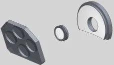
Fig.2 3-D Schematic of the optical system
1.2 Baffle design
For a typical all-reflective Cassegrain system, among all possible stray light path[5-6]. There are three main sources of stray light which form most stray light radiation on the image plane of the optical system: (1) aperture diffraction (single diffraction), (2) optical surface scatter (single scatter), and (3) baffle scatter plus optical surface scatter (multiple scatter). Single scatter stray light occurs when a stray light source directly illuminates the optics in the system. Some portion of the light will scatter in a direction that causes it to reach the focal plane. That is to say it scatters into the field of view. Once light has scattered into the field of view, it becomes stray light. Thus a basic goal of baffle design is to keep light from shining on the optics. Multiple scatter stray light occurs when stray light sources indirectly illuminate the optics. These paths cause stray light indirectly, by first scattering from the baffle surfaces and then illuminating the optics. Stray light from this source will always be smaller than direct scatter, but it may still be large enough to be of concern.
For a given minimum off-axis field angle of stray light source θ, a simple baffle tube is arranged in front of the primary mirror to reduce the shading factor S(θ) down to zero conventionally. However, the baffle tube is alwaysrather long, and the length is usually given by the following equation.

The fundamental principle is utilizing a long tube with ring vanes on the inside wall to produce multireflection. Each time the incident light hit on the baffle, the energy intensity is greatly attenuated. Consequently, after several reflections, the stray light is exhausted. Therewith the image corruption becomes neglectable. Although the performance of conventional outer baffle was convinced upstanding, in some cases where the structure dimensions are limited and the long optical baffle cannot be allowed.
In this paper, we propose a type of optical baffle with radical leaf for effective stray light suppression, in which some radial thin leaves are fixed within the main baffle tube symmetrically[7], see Fig.3. These thin leaves split the baffle aperture into some small sub apertures. Substituting the maximum linear dimension of sub aperture (a) into above equation for baffle length to replace (D) gives a shorter baffle length (L), which can still block the radiation from stray light source at a given field angle (θ) to the primary mirror.

Fig.3 Schematic of baffle with radical leaf
The main parameters of radical leaf baffle design should be inner-diameter (d), outer-diameter (D), subaperture width (a), leaf thickness (b) and length (L). The rejection angle (α) is decided by both sub aperture width (a) and length (L).

Here, we define a obscuration coefficient (Ф), which is a ratio of the area blocked by the baffle and the total aperture. When the inner-diameter (d) and the outerdiameter (D) are set, the obscuration coefficient (Ф) of the baffle is related to both of the thickness (b) and the number of leaves (n). Apparently, thicker b and larger n lead to larger Ф.
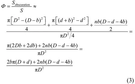
For instance, let the inner-diameter (d) and outerdiameter (D) are 30 mm and 95 mm, separately. There are six radial leaves. The sub aperture width (a) is 40 mm. Assuming stray light suppression field angle (θ) is 30°, the length of the conventional baffle (L) is defined as D/tanθ, thus the value is 165 mm, however, for baffle with radical leaf, the length is a/tanθ ≈ 70 mm.
In order to guarantee the suppression of the stray light, the baffle in this paper is designed with two rings and six leaves, as shown in Fig.4. Apparently, the obstruction is increased. As a matter of fact, it is considered at the very beginning of the optics design. The effective aperture is superfluous by increasing the size of the optics slightly. Thus, the obstruction caused by the baffle would not corrupt the performance of the optical system.

Fig.4 The view of baffle with radical leaf
As shown in Fig.5, the design of primary mirror baffle and secondary mirror baffle is follow by method mentioned by Hu et al.[8].
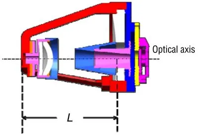
Fig.5 Side view of primary and secondary mirror baffles
The protection of the detector from stray light is not restricted, of course, only by placing of two conic baffles. They are destined for shielding from direct light and radiation, scattered by the tube walls. As shown in Fig.4, in order to prevent the stray light scattered from the bottom, vanes are introduced. Usually the first-order scattering properties of the vane structures are more important than whether the vanes are angled or not. Many results convinced that angled vanes would have a significant advantage over annular vanes[9]. Thus, considering the incident angle and the scanning range, the vane angle is chosen 45°. As a matter of fact, this accounts for the subtle but important difference in the results. The whole equipment is shown in Fig.6.
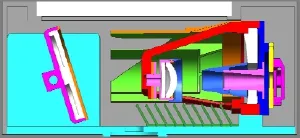
Fig.6 Side view of the system
Another important factor for the stray light analysis is the choice of coating. The use of aluminum suggests the use of black anodization. Some measurements indicate that the absorption of that coating could not be satisfying. Improvement could have been reached by sandblasting the aluminum sheet. This solution has been considered too risky due to the very low thickness of the sheet. The choice has thus been made to use Aeroglaze Z306 which is a well known paint for space application. Measurement made on samples indicates that BRDF was close to the modeled one[10].
2 Simulation analysis
As one of the common ways to define the merit function of stray light in an optical system, the point source transmittance (PST) is usually used to evaluate the baffle-blocking efficiency and generally obtained by Monte-Carlo analysis on computer. The PST formula is the ratio of the focal plane irradiance Ed(θ, λ) to the entrance aperture irradiance Ei(θ, λ).
For a rotational symmetry system, once the wavelength is fixed, the PST curve is easy to get by calculating the ratio under different off-axis incident angles in some certain direction. However, for axis asymmetrical situation such as the one in this paper, it becomes complicated. Both the azimuth and pitching are needed to be considered. The growth of computation complexity is square.
In this paper, the simulation is executed by TracePro, a stray light tracking software. 10 million rays have been traced. The flux per ray is 1 watt. The threshold is set 10-9. All the baffle surfaces are considered to be painted black paint. The ABg scatter parameters of the black paint is A = 0.07, B = 1, g = 0, and the absorption is 0.9. Fig.7 presents the level of stray light in different azimuth and pitching angles. According to the simulated datum, the curve shows that PST values are less than 10-9when incident angles are larger than the rejection angle (30°) which satisfies common requirement.
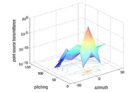
Fig.7 Wireframe drawing of the PST analysis
Although PST is a classic method to describe the stray radiation suppression for an optical system, lots of statistics data in different incident angles are needed for curve drawing. Plus, the result contains both regular light and stray light. Thus, it could only be a reference for design improvement and cannot compare with other systems[11]. Here we introduce a reverse ray trace method. That describes the stray radiation suppression with stray light coefficient (SLC), and could separate regular light from stray light. Take the center field of view for example to show how the reverse ray trace method works. Firstly, it is needed to build the same two mirror symmetrical systems as shown in Fig.8.

Fig.8 Reverse ray trace simulation in TracePro
In Fig.8, System 1 is the stray light filter, and System 2 is the light generator. The focus plane of System 2 is set as the source, besides, in order to guarantee covering the full field of view the emission divergence angle must be larger than the convergence angle of imaging rays. Consequently, the light transmits though system 2 reversely. The rays at the exit of system 2 could be considered as total energy reaching the focal plane. Those rays include not only regular imaging rays but also stray light. The rays keep on transmitting into system 1. The regular rays could pass though and reach the focal plane of system 1, on the contrary, the stray light is blocked. If the energy at the exit of system 2 is defined as total energy (Et) and the energy on the focal plane of system 1 is defined as effective energy (Ee). Then, the stray light coefficient (η) could be calculated by the following equation:

For system mentioned in this paper the SLC is 0.01, when the source is set at the center field of view. SLC could be easily obtained without mass of complicated computation. Moreover, if the source traverses the whole field of view, the SLC in different position could also be got. As shown in Fig.9, the minimum (ηmin= 0.01) appears at the center field of view, while the maximum (ηmax= 0.3) locate in the perimeter. The results could reflect the stray radiation suppression ability of the test system distinctly, and easily compare with other design.

Fig.9 Stray light coefficients for different positions in the view field
3 Conclusions
A new type of optical baffle with radical leaf for effective stray light suppression is proposed in this paper. Both the PST and SLC are analyzed to discuss stray radiation suppression performance of the system. Comparing to PST, the SLC could be easily obtained without mass of complicated computation. Moreover, SLC for different position in the field of view could also be got when the source traverses the whole field of view. The result reflects the stray radiation suppression ability of the test system distinctly, and affords helpful guidance for baffle design.
[1] Wang Hai-yong, Zhou Wen-rui, Cheng Xuan, et al. Image smearing modeling and verification for strapdown star sensor[J]. Chinese Journal of Aeronautics, 2012, 25(1): 115-123.
[2] Gautam A S, Gupta A, Singh G S. Optical design of off-axis Cassegrain telescope using freeform surface at the secondary mirror[J]. Optical Engineering, 2015, 54(2): 025113-025120.
[3] Wilson R N. Reflecting telescope optics II[M] 1st ed. 1999. Corrected 2nd printing 2001, Berlin, New York: Springer, 1999 xviii, 554 p.
[4] Ye Hai-shui, Gao Zhi-shan, Qin Zhen-yu, et al. Near-infrared fundus camera based on polariza- tion switch in stray light elimination[J]. Chinese Optics Letters, 2013, 11(3): 56-59.
[5] Kumar M S, Narayanamurthy C S, Kumar A S K. Design and analysis of optimum baffle for a Cassegrain telescope[J]. Journal of Optics, 2015, Springer: 1-6
[6] 郭力滔, 高天元, 孙景睿, 等. 卡塞格林式星敏感器杂散光分析[J]. 长春理工大学学报(自然科学版), 2015(2): 21-24. Guo Li-tao, Gao Tian-yuan, Sun Jing-rui, et al. Analysis of stray light in Cassegrain star sensor[J]. Journal of Changchun University of Science & Technology, 2015(2): 21-24.
[7] Zhang Kai-sheng, Zhang Zhi, Zhang Zhao-hui. Optical system design for lens with large relative aperture[J]. Proc. SPIE, 2015, 9676: 15-20.
[8] Hu Xiao-dong, Wang Wei-ke, Hu Qiang, et al. Design of CASSEGRAIN telescope baffles with honeycomb entrance [J]. Chinese Optics Letters, 2014, 12(4): 072901- 072904.
[9] Fan Zhi-gang, Hu Hai-li, Chen Shou-qian, et al. Stray light analysis for multi-target compounding hardware-inloop system[J]. Journal of Applied Optics, 2014, 35(2): 205-209.
[10] Mazy E, Stockman Y. Design and modelisation of a straylight facility for space optical instrument[J]. Optical Systems Design, 2012, 8550(1): 07-18.
[11] 钟兴, 张雷, 金光. 反射光学系统杂散光的消除[J]. 红外与激光工程, 2008, 37(2): 316-318. Zhong Xing, Zhang Lei, Jin Guang. Stray light removing of reflective optical system[J]. Infrared and Laser Engineering 2008; 37(2): 316-318.
[12] 胡晓东, 胡强, 雷兴, 等. 一种用于白天星敏感器的星点质心提取方法[J]. 中国惯性技术学报, 2014, 22(4): 481-485. Hu Xiao-dong, Hu Qiang, Lei Xing, et al. Method of star centroid extraction used in daytime star sensors[J]. Journal Chinese Inertial Technology, 2014, 22(4): 481-485.
1005-6734(2016)02-0175-05
星敏感器是惯性天文组合导航系统的关键传感器,星敏感器的光学系统设计及对杂散光的抑制是决定其能否实现测星的主要因素。提出一种改进型的卡塞格伦反射光学系统,该系统通过摆镜折叠光路并实现扫描,压缩了系统的体积,增强了系统的灵活性。进而针对该系统设计了一种基于基生叶结构的遮光罩,利用光线追迹软件在不同方位和俯仰角度入射下对系统进行了仿真分析,结果表明规避角以外的点源透射比可以达到10-9以下,满足系统使用要求。此外,鉴于传统点源透射比方法的计算量较大,还引入了杂散光系数的概念,通过对镜像系统进行反向光线追迹可以将杂散光分离,从而计算出杂散光系数,表征系统对杂散光的抑制能力。该方法可降低计算量,提高设计效率。
天文导航;星敏感器;卡塞格伦光学系统;杂散光;遮光罩
A
2015-11-25;
2016-03-16
航空基金支撑项目(61901060301)
胡晓东(1984—),男,博士、高级工程师,从事惯性天文组合导航研究。E-mail: huxd@163.com
10.13695/j.cnki.12-1222/o3.2016.02.007
用于星敏感器的马蹄形卡塞格伦反射式光学系统杂散光抑制方法
胡晓东,丁小昆,王维科,魏 青
(中国航空工业集团 西安飞行自动控制研究所,西安 710065)