负电阻电磁分支电路阻尼隔振系统试验技术研究①
2016-02-09张希农
严 博, 张希农
(1.浙江理工大学机械与自动控制学院, 浙江 杭州 310018;2. 西安交通大学机械强度与振动国家重点实验室, 陕西 西安 710049)
负电阻电磁分支电路阻尼隔振系统试验技术研究①
严 博1,2, 张希农2
(1.浙江理工大学机械与自动控制学院, 浙江 杭州 310018;2. 西安交通大学机械强度与振动国家重点实验室, 陕西 西安 710049)
给出了一种负电阻电磁分支电路阻尼隔振器,并开展了板结构的隔振试验技术研究。首先,分析了该隔振器的工作原理,给出了负电阻分支电路原理图,建立了板隔振系统的控制方程。其次,设计了板结构隔振试验测试系统,开展了板结构在正弦扫频,正弦定频,以及半正弦冲击载荷作用下的振动控制特性试验研究。测试结果表明,负电阻电磁分支电路阻尼隔振器能够有效地抑制结构的振动。
隔振;分支电路;负电阻;电磁
引 言
随着Hagood和von Flotow[1]首次提出了利用压电分支电路阻尼耗散结构的振动能量以来,分支电路阻尼振动控制技术得到了长足的发展。简单来讲,分支电路阻尼技术就是将设计的电路与压电或电磁线圈相连,通过电路耗散结构的振动能量,从而实现振动控制。
此前的研究集中在利用R-L-C构成的谐振回路耗散振动能量。近年来,Fleming[2,3]提出了一种合成阻抗分支电路技术,并研究了梁的多模态振动控制。此外,他还研究了基于LQR和H2算法的主动式电磁分支电路作动器。Cheng[4]研究了一种并联LRC式分支电路,并控制了梁结构的前两阶振动。近年来,负电容分支电路阻尼技术得到了长足的发展以及广泛的应用[5-6]。从原理上来讲,负电容能够抵消压电结构的等效电容,从而增大了电路的电流,提高压电作动器的振动控制效果。
本课题组开展了电磁分支电路阻尼振动控制技术的相关研究,并取得了一些研究成果。为了控制单模态振动,文献[7]提出了一种负电阻配电容分支电路,并成功地控制了梁结构的一阶振动。此后,文献[8]设计了一种负电阻电磁分支电路阻尼隔振器,并开展了梁结构的隔振特性研究,结果表明所提出隔振器有效地抑制了梁结构的振动[9]。为了控制多模态振动,文献[10]提出了一种负电阻负电感电磁分支电路阻尼,并开展了板结构的多模态振动控制特性研究。
本文设计出了一种圆筒式负电阻电磁分支电路阻尼隔振器,并以板结构为研究对象,着重设计相应的试验测试系统,开展了板结构在正弦扫频,正弦以及半正弦冲击载荷作用下隔振特性的试验研究。
1 电磁分支电路阻尼隔振器
1.1 电磁阻尼器模型
图1所示的为圆筒式电磁隔振器的结构原理图,其由一对同极正对的永磁体、电磁线圈、弹簧、中心轴,以及线圈架子等构成。当永磁体对与电磁线圈之间产生相对运动时,根据法拉利电磁感应定理,线圈两端会产生感应电动势。由楞次定理可知,当线圈闭合时,线圈会产生与永磁体和线圈相对运动方向相反的安培力,该力是一个与相对速度相关的变量,因此可将其称之为一种阻尼力。
电磁线圈和一负电阻分支电路相连构成闭合回路。从原理上来讲,负电阻能抵消线圈的内电阻,减小线圈的内阻抗,从而相应地增大控制电流,提高了电磁阻尼控制力。图2所示为负电阻分支电路与电磁线圈构成的闭合回路。
根据安培力定理,该阻尼力可以写为
fe=Cmi(t)
(1)
式中Cm定义为电磁耦合系数,其大小主要取决于线圈与永磁体的结构配置、线圈匝数以及磁场强度等,而与相对运动的速度无关。i(t)为线圈中产生的感应电流。根据法拉第电磁感应定理,线圈两端的感应电动势可以写为[8]
E(t)=Cev
(2)
式中E为线圈的两端产生的感应电动势,v为电磁线圈与永磁体之间的相对速度。当线圈两端和负电阻分支电路相连时,如图2所示,有
(3)
式中Le为线圈的等效内电感,Re和Rs分别为线圈等效内电阻和分支电路等效电阻。
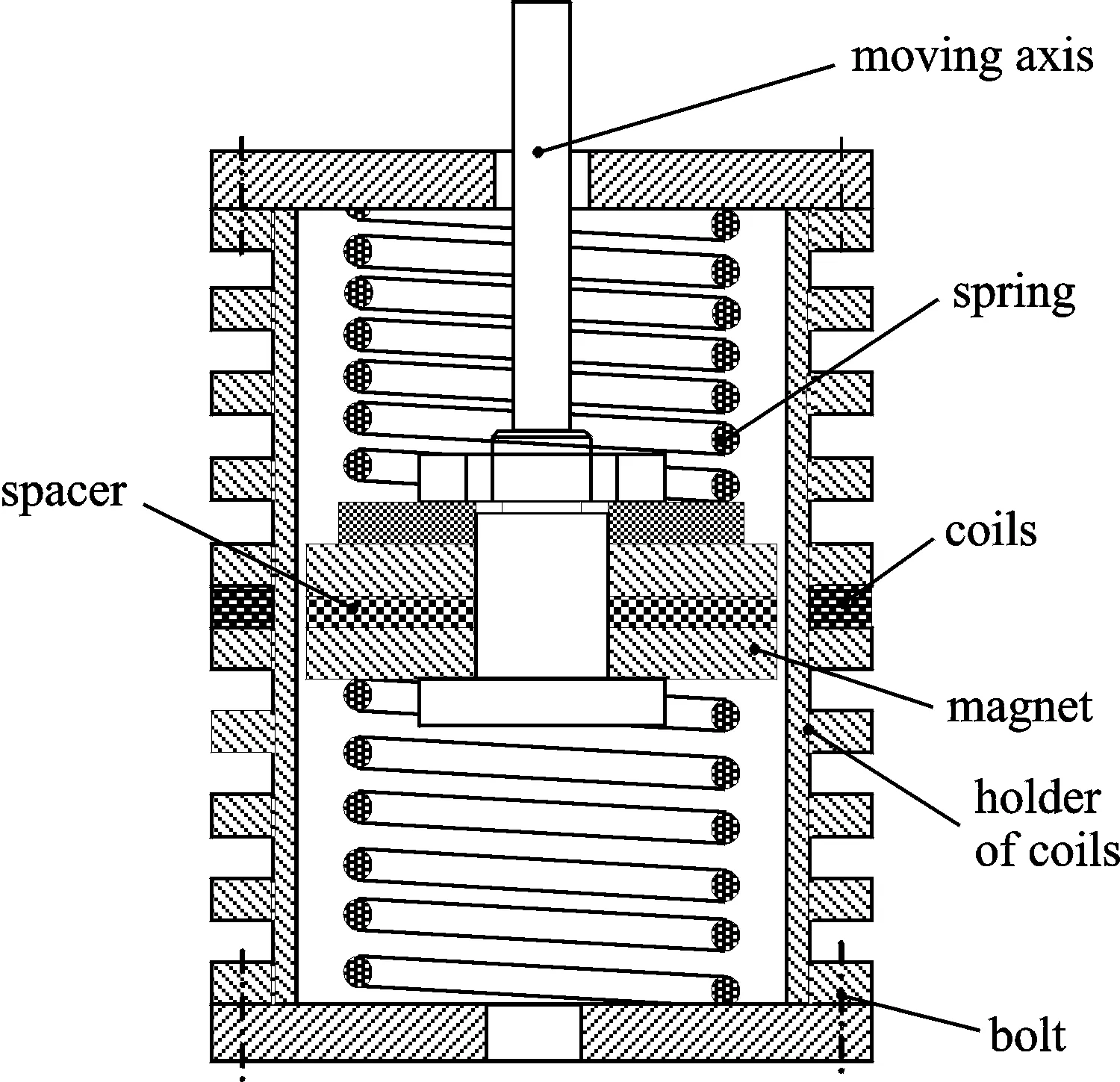
图1 圆筒式电磁隔振器结构原理图Fig.1 Schematic of the electromagnetic vibration isolator
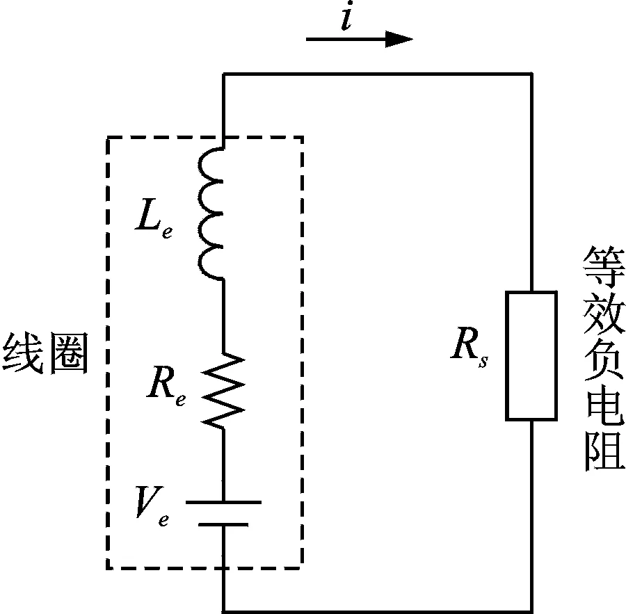
图2 负电阻与线圈构成的闭合回路Fig.2 Closed loop composed of the negative resistance shunt and the coil
1.2 等效负电阻分支电路模型
图3所示的为等效负电阻分支电路原理图,其中OPA544T的同向输入端电压为
(4)
式中u0为OPA544T的输出电压,对于电路中的Rs而言,其两端电压为
u--uo=u+-uo=iRs
(5)
因此,该电路的等效电阻为
(6)
由上式可以看出,当R2=R3时,Rs可理解为等效负电阻。下文中,将Rs简称为分支电路的负电阻。
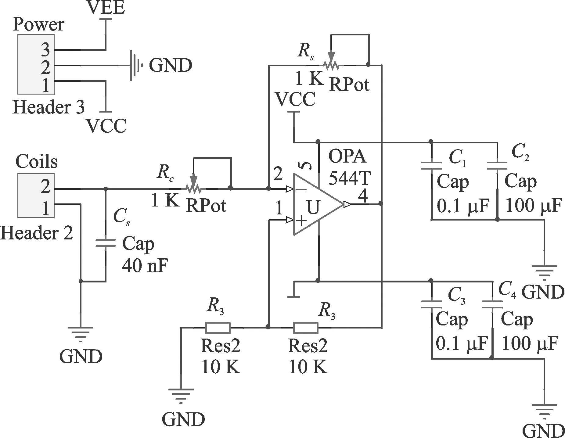
图3 等效负电阻分支电路原理图Fig.3 Schematic of the negative resistance
2 板结构隔振系统的控制方程
图4所示的为电磁分支电路阻尼板隔振系统原理图,其中,每个电磁线圈都分别串联一个所设计的负电阻电路。当系统受到基础激励u(t)时,根据基尔霍夫板理论,可知该系统的控制方程为
(7)
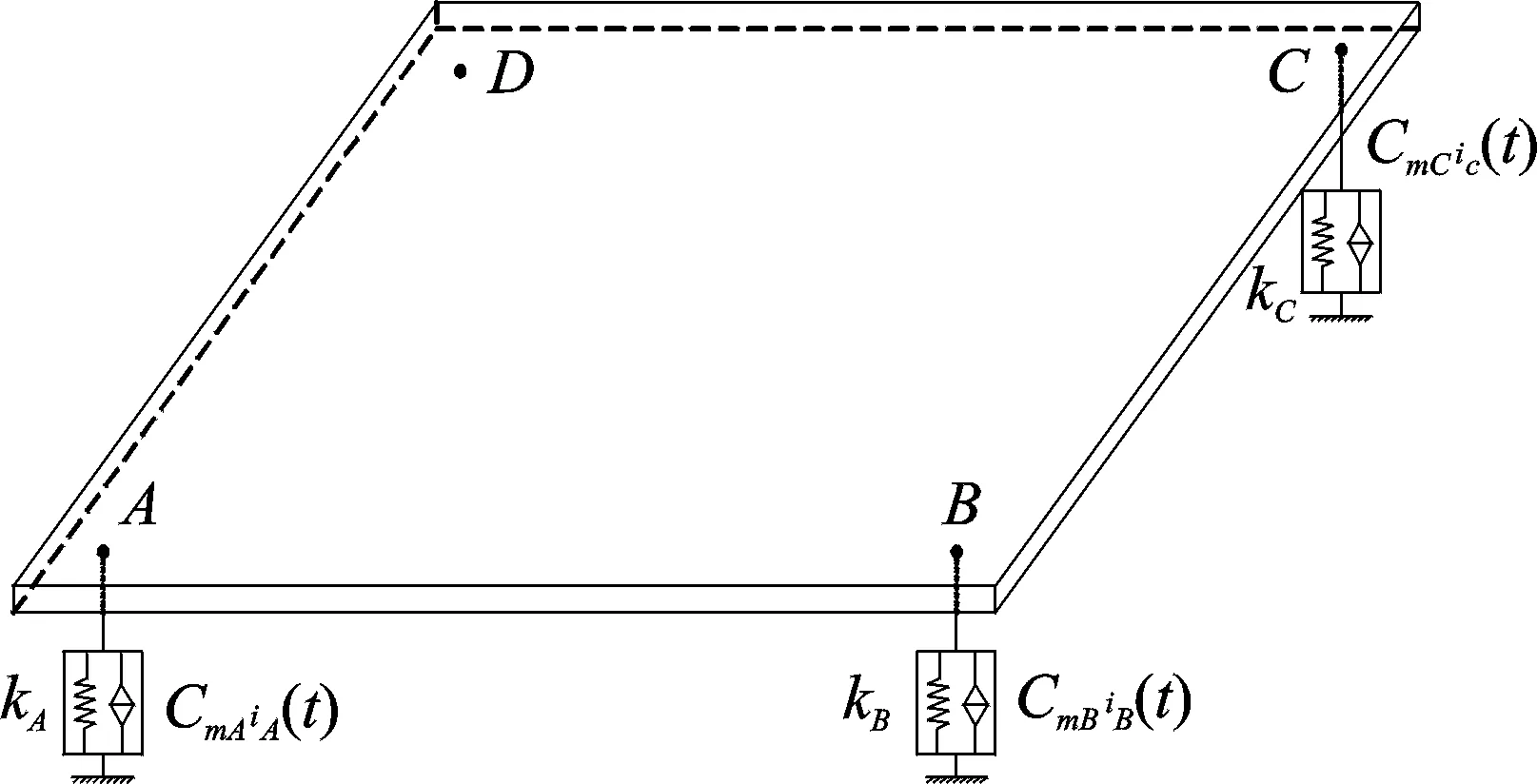
图4 板隔振系统原理图Fig.4 Schematic of the plate isolation system
3 板隔振的试验设计与结果分析
3.1 试验设计
图5为板结构隔振测试系统原理图,将4个隔振器和板通过夹具安装在振动台,安装细节如图6所示,其中,每个隔振器连接一个分支电路板。振动台由苏轼控制系统(SUSHI RC-300 控制器)和台面的加速度传感器构成的闭环系统进行控制。铝板的尺寸为350 mm×300 mm×2 mm。4个线圈的内电阻分别为14.2,14.3,15.7,13.2 Ω。将Rc选取为181 Ω,设置负电阻值为193,193,195,191 Ω。根据图5所示的试验系统,测试板结构在未控制和分支电路控制时的响应,激励方式主要有正弦扫频,正弦以及半正弦冲击。
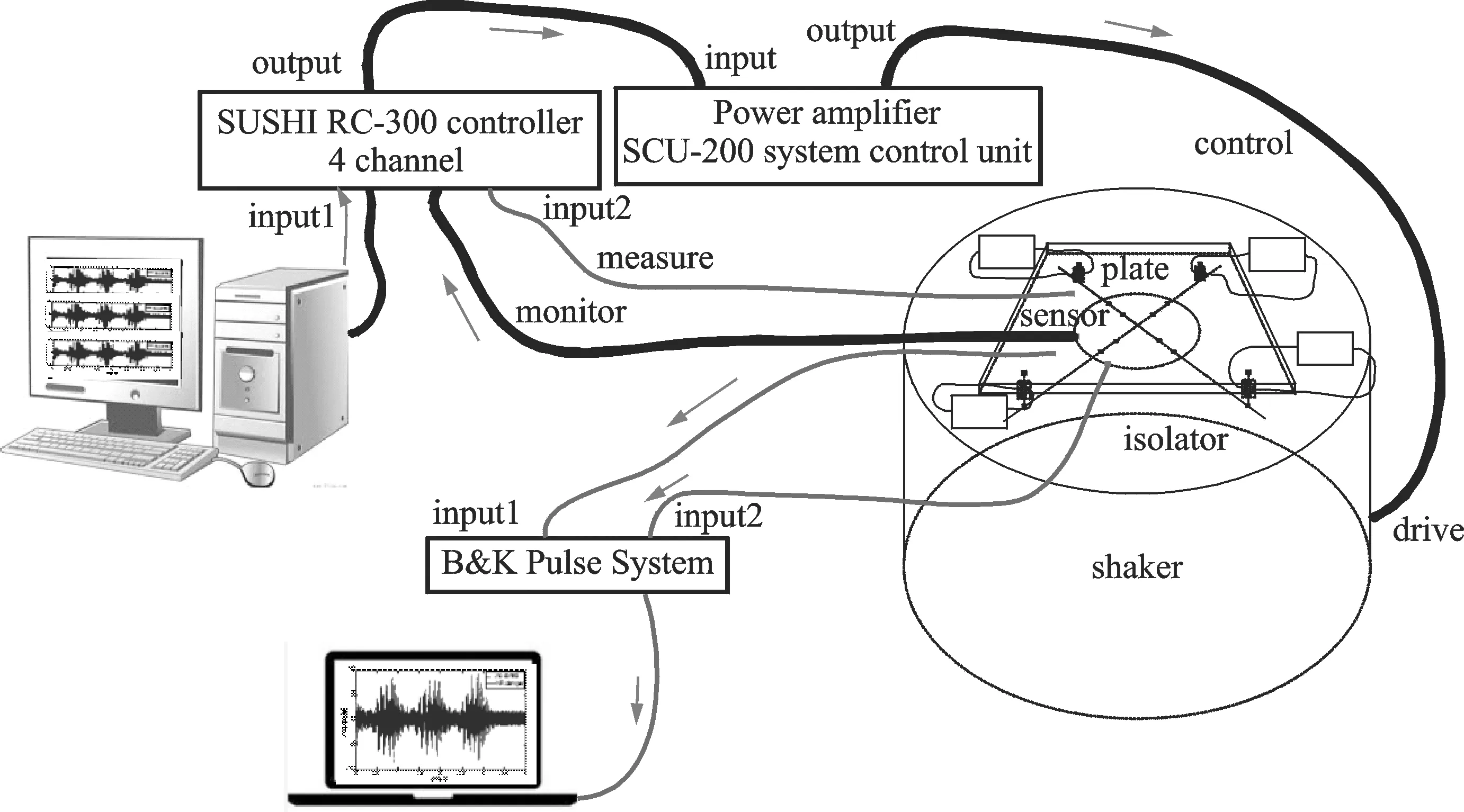
图5 板结构隔振测试系统原理图Fig.5 The diagram of text system of the plate′s vibration isolation
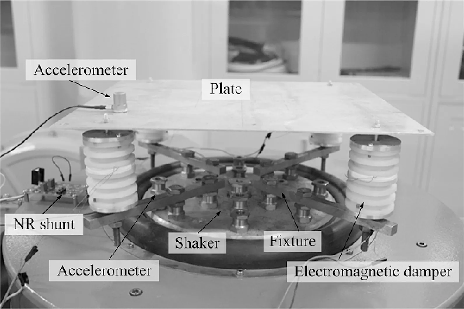
图6 板的安装图Fig.6 Photograph of the isolation system
3.2 试验测试及结果分析
3.2.1 幅频响应分析
图7为板结构上一点S(5 cm,7 cm)在未控制和负电阻分支电路阻尼器隔振时的幅频响应曲线对比,由此可以看出,采用负电阻电磁分支电路阻尼隔振器隔振时,板的振动几乎被完全隔离。
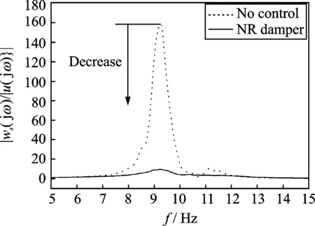
图7 板在未控制和负电阻电磁分支电路阻尼隔振时的幅频响应对比Fig.7 Frequency response comparison of the plate under no control and the negative resistance shunted electromagnetic damping vibration isolation
3.2.2 正弦响应
本节主要讨论当系统的输入为正弦载荷时,板结构在未控制和引入负电阻电磁分支电路阻尼隔振器隔振时的响应对比。图8(a)所示的为振动台的输入正弦加速度载荷,其频率为9 Hz,接近于板系统的一阶共振频率。此时,板结构在该激励下的响应如图8(b)所示,可以看出,在稳态响应阶段,引入负电阻电磁分支电路阻尼器时,板结构的幅值下降近75%。
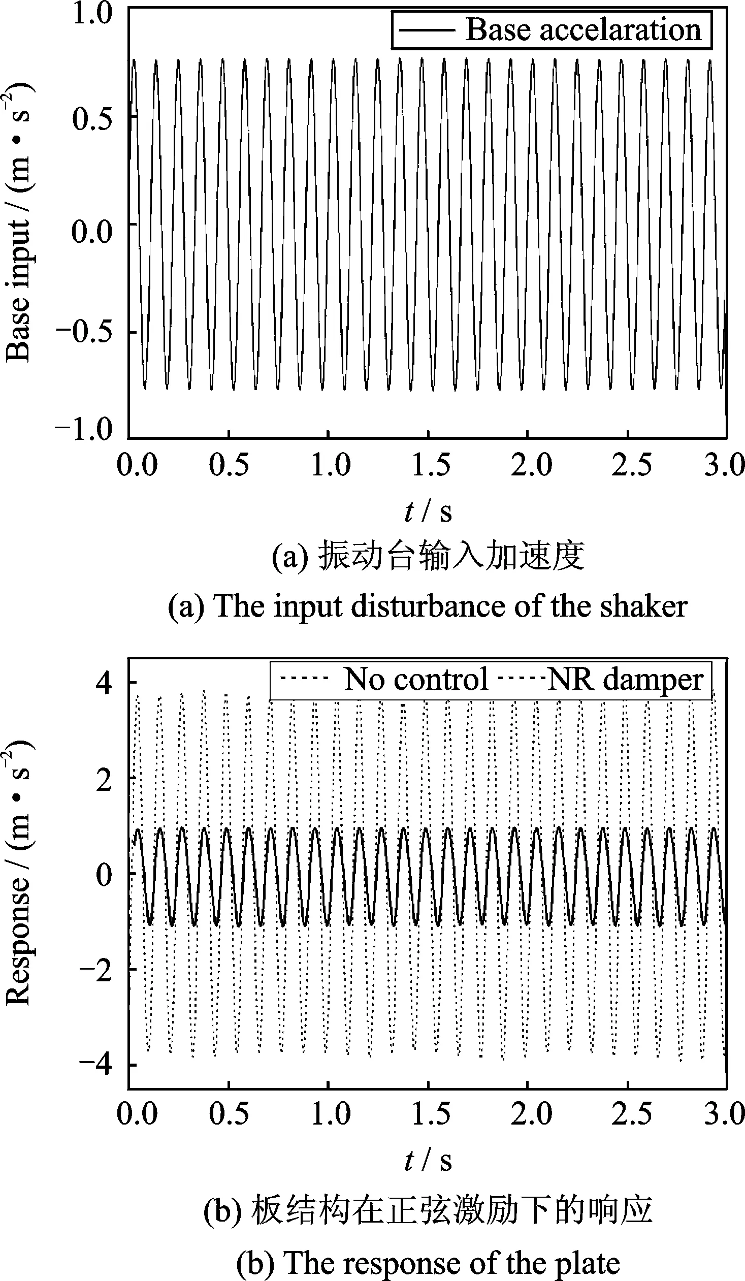
图8 试验谐响应分析Fig.8 Experimental harmonic response analysis
3.2.3 半正弦冲击
本节主要讨论板结构在半正弦冲击载荷作用下,阐述引入负电阻电磁分支电路阻尼隔振器对板结构抗冲击特性的影响。图9所示为系统在5 ms宽的半正弦加速度载荷下板结构的响应。可以看出,在使用负电阻电磁分支电路阻尼隔振器进行隔振时,板结构的最大冲击幅值减小,其衰减速度加快,即采用负电阻电磁分支电路隔振器可以有效地抑制板结构在冲击载荷作用下的振动。
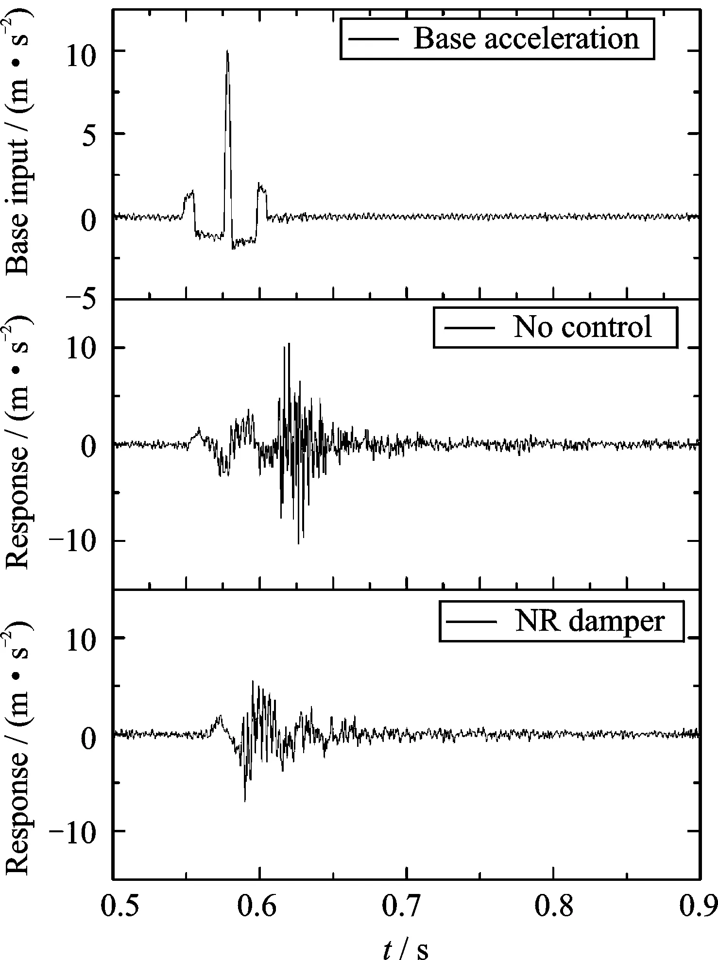
图9 5 ms半正弦冲击载荷下板的响应对比Fig.9 Response comparison of the plate under the semisine shock with duration 5 ms
4 结 论
本文提出了一种负电阻电磁分支电路阻尼隔振器,建立了该阻尼器的理论模型。基于基尔霍夫板理论,得到了板隔振系统的控制方程。设计了板隔振试验测试系统,开展了隔振系统的振动控制性能的试验技术研究。研究结果表明,在正弦扫频,正弦以及半正弦冲击载荷基础激励作用下,负电阻电磁分支电路阻尼隔振器能够极为有效地抑制板结构的振动。
[1] Hagood N W, von Flotow A. Damping of structural vibrations with piezoelectric materials and passive electrical networks[J]. Journal of Sound and Vibration, 1991, 146: 243—268.
[2] Fleming A J, Behrens S, Moheimani S O R. Optimization and implementation of multimode piezoelectric shunt damping systems[J]. IEEE Transactions on Mechatronics, 2002,7,87—94.
[3] Fleming A J, Behrens S, Moheimani S O R. Active LQR and H2shunt control of electromagnetic transducers[C]. 42nd IEEE Conference on Decision and Control, Maui, HI, 2003, 2294—2299.
[4] Cheng T H, Oh I K. A current-flowing electromagnetic shunt damper for multi-mode vibration control of cantilever beams[J]. Smart Materials & Structures, 2009, 18, 095036.
[5] B de Marneffe, Preumont A. Vibration damping with negative capacitance shunts: theory and experiment[J].Smart Materials & Structures, 2008, 17, 035015.
[6] Ji H L, Qiu J H, Cheng J,et al. Application of a negative capacitance circuit in synchronized switch damping techniques for vibration suppression[J]. Journal of Vibration and Acoustic, 2011 133, 041015.
[7] Niu H P, Zhang X N, Xie S L,et al. A new electromagnetic shunt damping treatment and vibration control of beam structures[J]. Smart Materials & Structures, 2009, 18, 045009.
[8] Yan B, Zhang X N, Niu H P. Design and test of a novel isolator with negative resistance electromagnetic shunt damping[J]. Smart Materials & Structures, 2012, 21, 035003.
[9] Yan B, Zhang X N, Niu H P. Vibration isolation of a beam via negative resistance electromagnetic shunt dampers[J]. Journal of Intelligent Material Systems and Structures, 2012, 23: 665—673.
[10]Zhang X N, Niu H P, Yan B. A novel multimode negative inductance negative resistance shunted electromagnetic damping and its application on a cantilever plate[J]. Journal of Sound and Vibration, 2012,331, 2257—2271.
Experimental investigation of negative resistance shunted electromagnetic
damping vibration isolation system
YANBo1,2,ZHANGXi-nong2
(1. Faculty of Mechanical Engineering & Automation, Zhejiang Sci-Tech University, Hangzhou 310018, China;
2. State Key Laboratory for Strength and Vibration of Mechanical Structures,
Xi′an Jiaotong University, Xi′an 710049, China)
In this research, a kind of negative resistance electromagnetic shunt damping vibration isolator is proposed, which is investigated experimentally. First of all, the isolator is built up theoretically, the schematic circuit diagram of the negative resistance shunt is developed and the governing equation of the plate system is derived. Secondly, the experiment of the isolation system of plate is setup. The response of the plated under the sweep sine, sine, and semi-sine excitation are tested. The results demonstrate that the negative resistance electromagnetic shunt damping vibration isolator can tremendously isolate the vibration of the plate.
vibration isolation; shunt; negative resistance; electromagnetic
2014-05-18;
2016-09-22
国家自然科学基金资助项目(11602223);浙江理工大学科研启动基金资助项目(16022060-Y);中国科学院太空应用重点实验室资助项目(LSU-2016-01-01)
O328;O327
1004-4523(2016)06-1057-05
10.16385/j.cnki.issn.1004-4523.2016.06.015
严博(1986—),男,讲师。E-mail: yanbo@zstu.edu.cn, goaheadyan@foxmail.com
张希农(1954—),男,教授,博士生导师。电话:(029)82668482;E-mail: xnzhang@mail.xjtu.edu.cn
