The CNC transformation of CA6140 lathe based on motion controller
2015-12-19GuizhiZHAOXiaoqiangWUXiaominSHANChunYouZHANGCollegeofMechanicalEngineeringInnerMongoliaUniversityfortheNationalitiesTongliao028000China
Gui-zhi ZHAO,Xiao-qiang WU,Xiao-min SHAN,Chun-You ZHANG(College of Mechanical Engineering,Inner Mongolia University for the Nationalities,Tongliao 028000,China)
The CNC transformation of CA6140 lathe based on motion controller
Gui-zhi ZHAO,Xiao-qiang WU,Xiao-min SHAN,Chun-You ZHANG*
(College of Mechanical Engineering,Inner Mongolia University for the Nationalities,Tongliao 028000,China)
CNC transformation of traditional machine has become the best choice for each factory to handle the traditional machine.In this paper,aiming at CA6140 lathe,CNC transformation overall program is proposed,the hardware selection is done.In order to meet need of the CNC system for lathe,new structure is designed.The scheme of CA6140 lathe CNC transformation is feasible,and it has a certain guiding significance.
Motion controller,Lathe,CNC transformation
Hydromechatronics Engineering
http://jdy.qks.cqut.edu.cn
E-mail:jdygcyw@126.com
1 Introduction
With the rapid development of manufacturing,the traditional tools can not satisfy the actual demand,gradually they are replaced by the CNC machine tool[1-2].The CNC machine tools have high degree of automation and good versatility.They have been widely used in manufacturing industry[3-6].But because that industry starts late in our country,many factories still occupy a large proportion of ordinary machine tools.The price of CNC machine tool is high.Compared with the purchase of new CNC machine tools,CNC transformation of the old machine is the most ideal way[7-8].The lathe is one of the most commonly used equipment in manufacturing industry,ordinary lathes are still used in many factories.In order to improve the processing technology and improve production efficiency,the old lathe can be transformed by the method of numerical control[9-10].On one hand,it can avoid waste of old lathes,on the other hand,it can realize automation of production,improve the processing efficiency,and ensure product quality,then improve the efficiency of enterprises.
2 Advanced methods for design
CNC transformation of lathe uses the most common one-CA6140 as an example,as shown in Fig.1.The overall scheme includes the structure and control scheme.
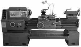
Fig.1 CA6140 Iathe
2.1 Control scheme
The essence of CNC transformation is that using CNC system to control the transverse and longitudinal motion of lathe guide rail,through the transverse and longitudinal movement,it can machine out the required shape.The transverse guide rail movement has definite function relation with longitudinal guide rail movement,the workpiece is machined according to the specified path through the transverse and longitudinal linkage,it can process the straight line,arc and free curve shapes.
The control principle of CNC transformation of lathe is shown in Fig.2,the core of the CNC system is multi axis motion controller.In order to ensure the economy,it still uses the original lathe spindle,the spindle is not transformed.Lathe uses the servo motor as driving device,and uses transverse guide rail and the longitudinal guide rail and the rest as actuators.The servo motors drive the transverse guide rail and the longitudinal guide rail to do the corresponding movement,and change the turret tool.In the system,users write program according to the drawing by computer.The written program can be directly sent into the motion controller,motion controller will send command to the servo drivers,servo drives will send pulse to the servo motors,servo motors do the corresponding actions. The HMI is used to monitor the data in the process of movement and send instructions.
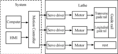
Fig.2 Structure scheme
2.2 Structure scheme
The control of the servo motor movement by controller uses the position control mode,the position mode has the advantages of high positioning precision and good reliability.But the structure of the original machine cannot use the servo motor to drive the transverse guide rail and the longitudinal guide rail and the rest to make the specified movement,it must carry on the transformation of its structure.
In order to install and use the servo motor,the lathe original carriage,feed box,light bar,and rest all should be removed.The original trapezoidal screw nut should be replaced by the ball screw,the servo motor drives screw nut through guide rail.The servo motor drives the ball screw to drive the slide motion mode in both transverse and longitudinal direction.
In order to further improve the degree of automation,the original fixed lathe rest will be replaced by automatic rotatable rest,the rotation is driven by a servo motor.Servo motor can receive instructions from the system,then drive the rest to the specified location.The transformed lathe is shown in Fig.3. Where,1 represents the longitudinal ball screw,2 represents the transverse ball screw,3 and 4 represent the servo motor,5 represents rotary automatic rest.
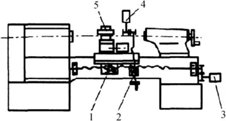
Fig.3 The structure of Iathe transformation
3 The hardware selection of control system
3.1 Motion controller
Motion controller is mainly used to process the data,and send out the instruction to control the operation of servo driver in accordance with the requirements[11].The multi axis motion controller must have the characteristics of high precision,fast speed,good stability,and good expansibility.By contrast,the PMC-2HSP interpolation type high-speed 2 axis motion controller is selected.
3.2 HMI
The HMI is mainly used to input data,display parameters,and perform the human-computer interaction,it is an important part of CNC system.And it is the only part to do direct interaction with users in the entire CNC system.HMI selection must first consider its function.Whether it can meet the function of CNC system,whether the programming is simple,and whether the Ethernet communication interface or USB interface etc.And we also should consider the screen size,color and other specific parameters.By contrast,the Delta(DELTA)touch screen man-machine interface DOP-B10S511 is selected.
3.3 Servo driver
Servo driver is used to drive the servo motor.The motion controller based on the feedback information issues a directive to the servo driver,servo driver drives servo motor to complete the corresponding action,and it is the most important components of CNC lathe.The selection of servo system must consider the power and torque firstly,in this case,the computing required power is 1 500 W,and torque is between 6-10 Nm,by contrast,the MOTEC full digital AC servo system is selected,the model is SEM120C1520,and its main parameters are:rated output power of 1 500 W,the rated torque of 7.16Nm,maximum torqueof 21.5 Nm.
4 The design of the transform of lathe
4.1 The design of ball screw
There are different types of standard ball screw already on the market,it can be directly used according to the need of design.The longitudinal ball screw is calculated,the parameters involved are from the CA6140 manual.
1)Calculation of cutting force
Cutting force calculation formula is as follows:

Where,PQis the maximum cutting power,in this case it is 6 kW;V is the maximum cutting speed in this case,V=100 mm/min.
After computing the cutting force Fcis 3 600 N.
2)Calculation and selection of ball screw
Axial load calculation formula is as follows:

Where,W is the total mass of moving parts;F is The friction coefficient of sliding guide rail,and generally it is 0.15-0.18,in this case F=0.17;K is The coefficient considering the influence of overturning moment,in this case K=1.16;Fzis the cutting force from the cutting direction,Fz=0.1-0.55Fc,in this case,Fz=0.5Fc=1 800 N.
After computing the axial load Fmis 2 932.6 N.
The average speed of ball screw:

Where,Vsis the feeding speed with maximum cutting force,and generally it is 1/2 of the most high feed rate,in this case the maximum longitudinal feed speed is 0.6m/min;L0is ball screw lead,in this case ball screw lead is 6mm.
The average speed of calculation nis 50r/min.
The calculation of the maximum equivalent load of ball screw is as follows:

Where,T is the service life of the ball screw,the service life of ball screw in this case is 20 000 hours(assuming 2 shift working system);fwis operation coefficient,generally it is 1.2-1.5,no impact can be 1.0-1.2,in this case it is 1.2.
After computing,the maximum equivalent load of ball screw is 13 563.2 N.
Do the selection of ball screw based on the above results.Consult the mechanical parts design manual[12],choose of ball screw type:WL4006-2.5×1.It is the double the ball screw nut of external circulation type with screw adjustment pre-tightening,the dynamic load rating is 16 100 N,strength,cyclic number of columns×ring number=2.5×l,accuracy class grade is 3[13].
The parameters are as follows:nominal diameter is 40mm,lead is 6mm,ball diameter is 3.696mm,screw diameter is 39.2mm,inner diameter is 35.9mm screw,nut diameter is 40.8mm,the outer diameter of the nut is 43.9mm.
Calculation of efficiency:

Where,r is Helix angle,it is 3°3′;φ is Friction angle,it is 13°45′;after computing,efficiency is 93%.
4.2 The design of automatic rotary rest
After the CNC transformation,lathe may involve many different cutting tools in the process,so the rest must do automatic rotation according to the actual needs.After years of development,there are standard tool products in the market,we can directly purchase it to use according to need.Automatic rotary rest applied to the economical lathe generally has four stations,six stations,and eight station,the four station rotary rest is used in this example[14-15].The frame structure of four station rotary rest is shown in Fig.4. Among them,1 represents upper body,2 represents movable pin,3 represents plate,4 represents fixed axis,5 represents worm,6 represents lower body,7 represents gear,8 represents clutch wheel,9 represents hall element,10 represents magnetic steel.
According to the actual situation of CA6140 lathe,the Changzhou LDB4-6140 four position electric rest was selected,its technical parameters is shown in Table 1.
There are four tools installed on the rest and they are interchangeable.In actual operation,the system sends out the tool change signal,then rest correspondingly acts.When the action is completed,it feedback to the system,the system executes the next operation. Because the connecting hole of the rest is relevant,it can directly be installed on the CA6140.
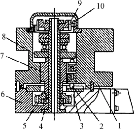
Fig.4 Four-station rotary turret structure
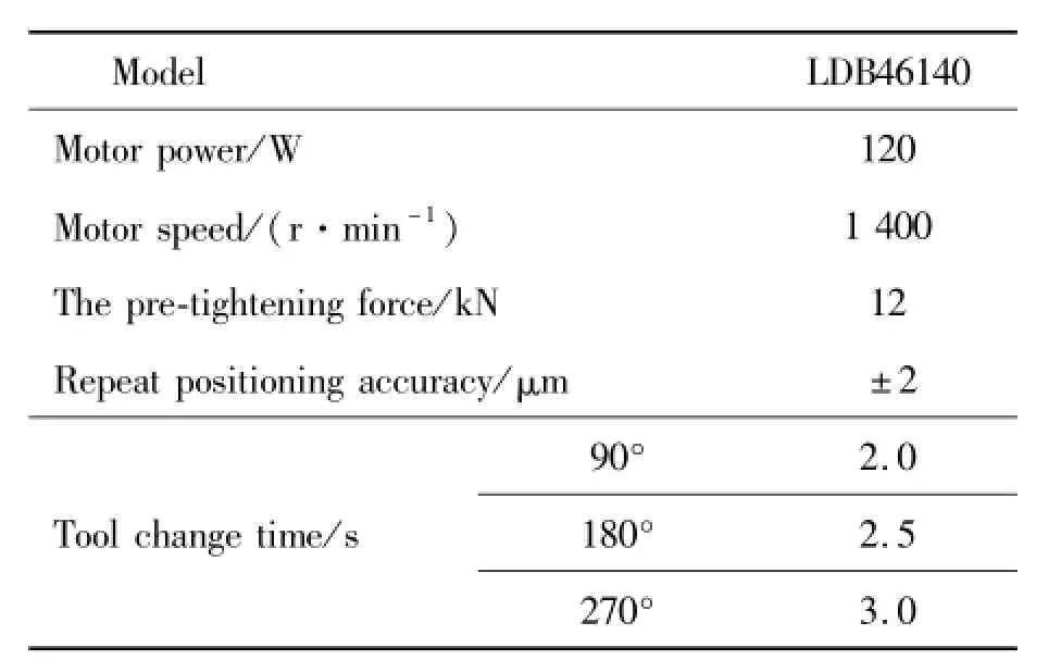
TabIe1 LDB4-6140 four-position eIectric turret technicaI parameters
4.3 The design of ball screw
The transformed CNC lathe can do the operation and monitor the parameters through the HMI.Design of man-machine interface is shown in Fig.5.Manual mode and automatic mode can be chosen.Both the machine coordinates and the workpiece coordinate can be monitored.The speed can also be set up and monitored,it can meet the requirements of CNC lathe.
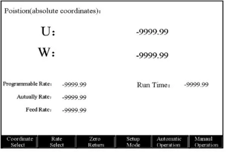
Fig.5 ControI interface
5 Conclusions
The development of high and new technology brings certain impact to the traditional processing method,it has become an inevitable trend that numerical control machine tools will replace the traditional ones.But many factories still has a lot of traditional machine tools,from the view of economy and reliability,the CNC transformation of traditional ones is the best way to avoid waste and improve processing efficiency.In this paper,the CNC system is built based on the motion controller as the core,CNC transformation of lathe CA6140 is finished.Put forward the general solutions and the structure transformation measures are put forward,it has an important meaning to improve the processing precision and the degree of automation of lathe.
Acknowledgements
This paper is supported by National Natural Science Foundation of China(No.6144041).
[1]Zhang Fang.Fault diagnosis and repair of NC machine tool[J].Reading writing calculation(Teaching and Research),2014(17):354.
[2]Han Ruibao.Discussion on the numerical control transformation method of common machine tool[J].Science and technology innovation and Application,2012(33):114-115.
[3]Shen Junda.Numerical control reform of ordinary lathe[J].Electrical and mechanical engineering,2006(2):26-29.
[4]Liu Shulin.The innovation direction of domestic high-end CNC machine tools[J].CNC machine tool Market,2013(10):18-20.
[5]Zhang Kejian,Li Meng.Application of universal horizontal CNC lathe in turning slender shaft parts[J].CNC machine tool Market,2011(11):56-57.
[6]Cao Wanyun.Repair and maintenance of CNC machine tool electric[J].East China Science and technology:Academic E-dition,2012(7):312.
[7]Wang Yuping,Cong Xiaoxia,Kong Xiaohong etal.Numerical control transformation design of general lathe[J].E-lectrical engineering technology,2004(3).
[8]Yu Shengmei.Numerical control technical reconstruction of the old machine[J].Mechanical and electrical integration technology at home and abroad,2000(1):35-38.
[9]Zhu Fangzheng,Kong Ya.How to improve the status of CNC machine tools in the mold processing[J].Silicon Valley,2012(5):155.
[10]Song Jianwu.Numerical control transformation of common lathe[J].Journal of Zhangjiakou Vocational and Technical College,2005(1):24-27.
[11]Yang Hongbo.PLC servo control in the application of flying saw machine[J].Mechanical and electronic,2009(11):31-33.
[12]Wu Zongze.Mechanical parts design manual[M].Beijing:Mechanical Industry Press,2004.
[13]He Hongxia.Selection and calculation of ball screw feed system in CNC CA6140 lathe[J].Coal mine machinery,2007(7):26-29.
[14]Guo Yonghuan.Development direction of the turret tool post for CNC lathe[J].Machine Tools and Hydraulic,2006(6):43-46.
[15]Huang Guansheng,Zhang Yongqiang,Wang.The construction and development of CNC tool management system[J].Textile machinery,2007(1):54-57.
基于运动控制器的CA6140车床数控改造
赵桂芝,吴晓强,单晓敏,张春友*
内蒙古民族大学机械工程学院,内蒙古通辽 028000
传统机床的数控化改造已成为各个工厂对传统机床应用的最佳选择,针对CA6140普通车床,提出数控改造整体方案,做出了硬件选型。为了适应数控系统,对车床进行了结构设计分析,本方案应用在CA6140车床上切实可行,具有一定的指导意义。
运动控制器;车床;数控改造
10.3969/j.issn.1001-3881.2015.12.016Document code:A
TH215
1 September 2014;revised 22 December 2014;accepted 6 March 2015
*Corresponding author:Chun-you ZHANG,Professor.
E-mail:wangzai8402@163.com
猜你喜欢
杂志排行
机床与液压的其它文章
- Research of numerical simulation on the spatial distribution of plasma antenna radiation field based on MATLAB
- Failure analysis for spindle system of CNC machine tools based on FMECA
- A valve can be designed to stabilize the gas-liquid flows
- Simulation analysis for punching machine driven by linear motor
- Application of improved PSO-based to neural network control system of parallel mechanism
- Dynamic parameters identification withconsidering hyper-viscoelasticof rubber bushing
