A valve can be designed to stabilize the gas-liquid flows
2015-12-19YeqingCHENYajunLIUZiyangHUANGMaoqingLISchoolofMechanicalAutomotiveEngineeringSouthChinaUniversityofTechnologyGuangzhou510642China
Ye-qing CHEN,Ya-jun LIU,Zi-yang HUANG,Mao-qing LI(School of Mechanical&Automotive Engineering,South China University of Technology,Guangzhou 510642,China)
A valve can be designed to stabilize the gas-liquid flows
Ye-qing CHEN*,Ya-jun LIU,Zi-yang HUANG,Mao-qing LI
(School of Mechanical&Automotive Engineering,
South China University of Technology,Guangzhou 510642,China)
Fluctuations of the flow and pressure drops exist widely in the two phase flow,which would cause the equipment to produce severe fatigue damage and even result in malfunction.Therefore,it is necessary to control the flow and pressure drops at appropriate range in two phase flow.This paper firstly models and analyzes a hydraulic element recorded in an ancient Chinese book“Ridge outside Pickup”,the objective of which is to regulate the flow rate,only a specific pressure drop can the device release fluid flow out.A mathematical model based on Euler equation and Bernoulli equation[1]is proposed to analyze the fluid field distribution and the mechanism of the whole device,and the effect of different typical stream pattern(Laminar,Turbulent and Gas-liquid flows)have been fully considered.Numerical simulation is carried out to validate the analytical solution.By optimizing diameter ratio of the device and implanting sensor part,a new valve can be designed to solve the problem of the flow fluctuation in gas-liquid two phase flow.
Hydraulic device,Ridge outside Pickup,Valve,Fluent
Hydromechatronics Engineering
http://jdy.qks.cqut.edu.cn
E-mail:jdygcyw@126.com
1 Introduction
An old Chinese book“Ridge outside Pickup”,which was wrote by Zhou Qufei in Song dynasty(A. D.1178),introduced a hydraulic device which is used to regular the flow rate for drink.This drinking-rateadjusting device is 0.6 m in length,with a float made of the bamboo inside the pipe.It is popular in the tribes of the southern China for controlling the drinking speed in an appropriate scope.Only a specific pressure drop can make the device release the fluid. Larger or less pressure drop applied will cause the float move up or down respectively leading to blocking.Therefore,regulated through the float,the device can work as a valve to reduce fluctuations as well as control the flow in a steady rate.
It is amazing that this device with so simple structure can control the flow velocity in a stability range and can be widely applied in the southwest china. With the modern theory of the fluid mechanics,the theoretical model of the device can be deduced and numerical simulation is conducted to validate the effectiveness of the theoretical model.In practical situation,fluctuations of the flow and pressure drops are frequently happening in pipeline flows due to the extraneous distraction.Water hammer results of extraneous distraction most of time,which will cause unsteady pressure and flow in pipelines.Gas-liquid flow will also arouse large flow fluctuations in flow,which damages the valves and other parts in pipe.Hence,a special valve is usually introduced to control the flow in engineering field.In general,the pressure drop of the gas-liquid flow in pipeline flow is mainly influenced by the void fraction and flow velocity[1].In most cases the void fraction is usually difficult to control while flow velocity is relatively easy to regulate[2-3]. Therefore,using a special flow valve to control the two phase flow through flow velocity is quite possible.In-spired by such a device,a schematic of a new valve which is able to reduce flow fluctuation theoretically is proposed.
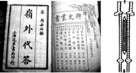
Fig.1 Ridge outside pickup(A.D.1178)
2 Modeling and simulation
This paper firstly models and analyzes an uniform drinking-rate-adjusting device recorded in an old Chinese book“Ridge outside Pickup”,which uses a float valve to maintain a constant drinking rate.And the working principle of the device is mainly derived based on the mathematical model that has been constructed.
2.1 Device in laminar flow
2.1.1 Analysis of the float inside the device
Since the float is the medium to connect flow field with the outside force,so the float should be analyzed priority when we analyzed the working principle of the whole device.And then the float is considered separately and the equation can be obtained:

Before the flow field is analyzed by the Bernoulli equation,following assumptions are proposed:
1)Due to the low velocity of fluid flow,the flow pattern can be considered as laminar flow distribution.
2)L2 segment can be considered as the annular pipe.
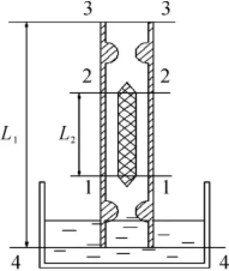
Fig.2 ModeI of the device
According to the above assumptions,the equation of 1-2 section can be proposed by the Bernoulli equation:

Considering the mass conservation equations,the equation can be simplified further.

Then it can be derived:

Where Δpfis the variation of the static pressure caused by the velocity of flow,and then Δpfcan be derived by the Fanning equation:

In the laminar flow regime,λ2can be derived by the Hagon-Poiseulle equation and Fanning equation:


At last,the pressure drop of the 1-2 section can be obtained:

2.1.2 Simultaneous equations
Base on the pressure drop and the resultant force of the float that has been derived previously,simultaneous of the flow equations and the float equations can be proposed:

Where

Substituted into above equations:

As can be indicated from the equation,the resultant force of the float is proportional to the flow rate. Therefore,When Ft=0,the unique steady state speed uecan be determined.
2.1.3 Modeled and analyzed of the whole device
Base on the fluid equation and float equation that have been derived previously,the whole pipeline should be considered so as to analyze the effect that the external force acted on the flow and the float.The equation of whole pipeline can be proposed by the Bernoulli equation:

As for A4>>A3,u4=0,then the equation could be further simplified:

Where

Where,∑h′fis straight pipe resistance loss;∑h"fis local resistances loss.
Then the pressure drop of the whole pipeline could be obtained further:

Considering the equilibrium equation of the float that has been derived previous:

As can be indicated from the equation,pressure drop of the whole pipeline is proportional to the flow rate.When Ft=0,the unique steady state velocity ueis determined,and the unique pressure drop of the whole pipeline Δp34is determined as well.
2.2 Device in turbulence
The flow pattern is considered as laminar flow distribution in the previously analysis,which is available to simplify the analysis process.In large Reynolds number,the laminar flow is invalidate so turbulent model should be used.Therefore,it is necessary to propose some more complicated flow stream pattern. This paper mainly considers the turbulence and gasliquid flows.
When the flow pattern is considered as turbulence,the motion of fluid is more complex than laminar flow. But it can still be analyzed by the Bernoulli equation.
Simultaneous fluid equations and float equation:(balanced equation of the float):

The equation of 1-2 section can be proposed by the Bernoulli equation:

Further simplified:

Where

When the flow pattern is considered as turbulence,the calculation of λ is more complex than the laminar flow.And the λ can be calculated by BulaHuges formula as follows:

Balanced equation of the float can be obtained

Where:

The equation of whole pipeline can be proposed by the Bernoulli equation

Where

The analysis method of the turbulence is the same with laminar flow,but the calculation of the λ is much complex than laminar flow.As for different working condition,it is important to choose most reasonable calculation formula for the λ.As a result,when other parameters are given,the pressure drop of the whole pipeline and outlet velocity are mainly determined by diameter ratio k.
2.3 Device in gas-liquid two phase flows
When the flow pattern is considered as gas-liquid flows,the calculation formulas of the pressure drop mainly include homogeneous flow model and separate flow model[4-5].And homogeneous flow model is introduced to calculate pressure drop here due to the small pipe diameter of the device and low flow velocity.Base on the gas-liquid two-phase flow theory,the balanced equation of the float can be obtained.

Where

The average viscosity can be calculated by Mike-Damm formula[6]:

Then the equation of 3-4 section can be proposed by the Bernoulli equation:
Where
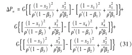
Base on the mathematical equations that have been derived,when other parameters are given,the pressure drop of the whole pipeline and outlet velocity are not only determined by diameter ratio k,but also by the mass gas content rate x.
2.4 Numerical simulation
In order to verify the rationality of the theoretical model,numerical simulation is carried out by FLUNET in this paper.
The parameters of device are set early for approximate calculation based on theoretical model before the numerical simulation:d1=2 cm,k=0.5,d2=kd1= 1 cm,L1=10 cm,L2=4 cm,ρf=1.3×10³kg/m3,ρj=0.935×103kg/m3,40%Alcohol,μ=2.91× 10-3Pa·s(20℃)
The approximate calculation based on theoretical model can be deduced:

And the local resistance of pipeline can be calculated:

Where:

Then:
Δp34=1.176 7×10⁴Pa,u3=2.88 m/s The pipeline model is simplified due to the complex structure of device in the processing of modeling.And the steady state of float is mainly considered in the simulation.In the process of simulation,2D model is considered and the flow field mutations happened in the hole is idealized for convenient modeling.The basic parameters are introduced for simulation:d1= 20,d2=10,L1=100,L2=40,grid format is Tri-Pave.And the inlet pressure and the outlet pressure are mainly considered for boundary conditions,then the grid model can be carried out.

Fig.3 Grid modeI
The finite volume method[7]is taken to discrete the governing equations in FLUENT.In the solver,the Standard Laminar and SIMPLE is selected for solution,Second Order is taken as difference scheme and Second Order upwind is considered for accuracy.Considering the speed of convergence,1e-3 is taken as the convergence of residuals.Then the preliminary simulation results can be carried out by FLUENT.
Fig.4 shows that the color of velocity contours on the two sides of the float is obviously darker than other parts of the pipeline,which means the flow velocity is relatively larger.However,the color of velocity contours near the outlet of pipeline is light and relatively uniform,which shows that the flow velocity near the outlet is low and going to stable.

Fig.4 VeIocity contours
Due to the effect of the float structure,considering changing the float structure from flat bottom structure into pointed bottom structure.
Fig.5 and Fig.6 show that the flow and pressure distribution of pointed bottom structure is more uniform than flat bottom structure,which indicates that optimizing the structure of the float is beneficial for stabilizing outlet flow and pressure fluctuation.Pointed bottom structure may be more available for the separation of the fluid boundary layer and perform a better effect of stabilizing flow.

Fig.5 VeIocity contours

Fig.6 Pressure contours
The results of the simulation indicates that the flow velocity near the outlet of pipeline in stable state is approximately 2.52-3.36 m/s,which is close to the value calculated through the theoretical mathematical model,the latter is u3=2.88 m/s,which shows that the mathematical model derived previously is relatively rational.
3 Discussion
Base on the above mathematical models and simulations,it can be deduced that this uniform drinkingrate-adjusting device recorded in“Ridge outside Pickup”can mainly control the drinking speed rely on drinker’s regulation.
When Δp34=Δp34e,then u3=ue,the float is in a steady state,the drinkers can drink at a steady rate;
When Δp34>Δp34e,then u3>ue,the float will rise until plug the hole due to the upward resultant force. Then drinkers have to reduce the suction so as to drink successfully;
When Δp34<Δp34e,then u3<ue,the float will fall until plug the hole due to the downward resultant force.Then drinkers have to increase the suction so as to drink successfully.
Through the above theory,we can get a conclusion that only in the condition Δp34e=Δp34,the drinker could drink successfully.As a result,the flow rate of the alcohol could be controlled in a steady rate with the regulation of the drinker.However,this device exist some obviously defects,such as it can’t work normal without drinker’s involvement and it can only control the flow in a very small scope.Hence,based on such device,we can propose a new method to control the flow in pipeline.
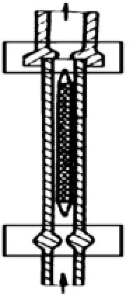
Fig.7 Optimized vaIve
As indicated from previous theory,the pressure drop of the whole pipeline only depends on the outlet velocity when other parameters are given.In other words,there is unique steady state velocity ue and pressure drop of the whole pipeline Δp34ewhen diameter ratio k is determined,any inappropriate velocity would cause the equipment instability.With such theory,a new valve can be designed to apply in pipeline flow for controlling pressure drop and flow in an appropriate scope.By optimizing diameter ratio of the device k,the stable state outlet velocity u3can be controlled in a narrow scope.In engineering application,this theory can be applied conversely.Through the given flow scope based on the engineering requirement,diameter ratio of the new valve k can be designed.As a result,the new valve can be designed targeted with different engineering demands.When diameter ratio is determined,the mechanical structure part of new valve is designed completed.Through implanting sensor part in the ends of device,the new valve can implement the function of stabilizing flow fluctuation.The sensor part is connected with control module to sense status of the float.When float is in a state of imbalance,the sensor part will transmit pulse signal to control module.Based on the analysis of these pulse signals,control module will regulate pump speed to restrict the flow in appropriate scope which can satisfy specific engineering requirement.As a result,the pressure drop fluctuation in pipe will reduce a lot when flow is constricted to a narrow range.
4 Conclusion
Through analyzing the flow field distribution and the working principle of the uniform drinking-rate-adjusting device recorded in an old Chinese book“Ridge outside Pickup”based on Euler equation and Bernoulli equation,the reasonable mathematical models for numerical simulation can be established,and it reveals that the pressure drop of the whole pipeline depends only on outlet velocity when other parameters are given,which means there is unique steady state velocity and pressure drop of the whole pipeline. Meanwhile,the effect of different typical stream pattern,such as laminar,turbulent and gas-liquid flows has been fully discussed,the results indicated that the mathematical model is also applicable for turbulence and gas-liquid flow.After that,numerical simulation of flow field is carried out by commercial Fluent when float is in balance state.As a result,the physical mathematicalmodelisprovedrelativelycorrect. Through theoretical analyses,the principle of the device can be proposed and some obviously defects are revealed.This paper then demonstrates a new method can be applied in two phase flow based on such uniform drinking-rate-adjusting device recorded in an old Chinese book“Ridge outside Pickup”.Base on the engineering requirement,the diameter ratio of the new valve can be obtained.When diameter ratio is determined,the mechanical structure part is designed finished.Through implanting sensor part in the ends of device,the new valve can implement the function of stabilizing flow fluctuation in two phase flow.

NomencIature
Acknowledgements
This paper is part of the research project:the innovation fund project of small and medium-sized enterprises(No.13C2621440518)and research project Enterprises and institutions entrusted to technical development project(No.D8140840).
Thanks to the project team for support of this research.
[1]Zhong Li,Wu Qin,Ma Sipeng.Principle of chemical engineering[M].Beijing:Chemistry Industry Press,2008.
[2]Yan Changqi.Gas-liquid two-phaseflow[M].Harbin:Engineering University Press,2009,11.
[3]Mandhane J M,Gregory G A,Ariz K.Flow pattern map for gas-liquid flow in horizontal pipes[J].Int Multiphase Flow,1974(3):537-553.
[4]Okosawam,Kozaw A Y,Inoijlea A.Study on two-phase cross flow,Part111:charaeteristies of unsteady flowbehavior[J].Int.J.MultiPhaseFlow,1986,12(2):18202.
[5]Nicklin G J,Davidson J F.Two phase flow[M].Inse Mech Eng Symp,1962.
[6]Prandtl L,Svard Tichy K O,Ludwig Hart K.Prandtl-Essentials of Fluid Mechanics[J].Beijing:Cornell University Press,1981.
[7]Anderson J D,Yao Chaohui.Computational fluid mech-anics[M].Beijing:Tsinghua University Press,2010.
一种能应用于气液两相流的新型稳流阀设计
陈叶青*,刘亚俊,黄子洋,李茂青
(华南理工大学机械与汽车工程学院,广州 510642)
流量与压降的波动广泛存在于气液两相流中,并且会对设备造成严重的疲劳损伤甚至导致设备失效,因此降低气液两相流中的流量波动与压降差波动是有必要的。首先对中国古书《岭外外答》中记载的一种液压装置进行了理论分析,该装置主要功能是实现稳流效果,并且只有合适的压差才能使其正常工作;利用欧拉方程与伯努利方程对整个装置的流场与工作原理进行了系统的分析,在分析过程中考虑了流体不同流态(层流、湍流、气液两相流等)对模型的影响,并根据建好的模型应用FLUENT软件对流场进行了仿真模拟。在此装置基础上,论证通过对其管径比以及结构的进一步优化以及植入传感模块可设计出一种能应用到气液两相流的稳流装置。
液压装置;岭外代答;阀;Fluent
10.3969/j.issn.1001-3881.2015.12.003Document code:A
TH137.52+2
*Corresponding author:Ye-qing CHEN,Postgraduate.
E-mail:978674210@qq.com
猜你喜欢
杂志排行
机床与液压的其它文章
- Research of numerical simulation on the spatial distribution of plasma antenna radiation field based on MATLAB
- Failure analysis for spindle system of CNC machine tools based on FMECA
- The CNC transformation of CA6140 lathe based on motion controller
- Simulation analysis for punching machine driven by linear motor
- Application of improved PSO-based to neural network control system of parallel mechanism
- Dynamic parameters identification withconsidering hyper-viscoelasticof rubber bushing
