The Accuracy of Mathematical Models in Simulator Distributed Computing
2015-12-13KvasnicaKvasnica
I.Kvasnica,P.Kvasnica
The Accuracy of Mathematical Models in Simulator Distributed Computing
I.Kvasnica1,P.Kvasnica2
The issue of simulation of decentralized mathematical models is discussed in the paper.The authors’knowledge is based on a theory of design of decentralized computer control systems.Their knowledge is gained in the process of designing mathematical models that are simulated.A decomposed control system is required to meet the conditions of observation and control.The methodology of a multi-model design is based on main principles of object orientation such as abstraction,hierarchy,and modularity.Modelling on a parallel architecture has an impact on a simulator system.The system is defined by the equations shown below.An important part is the way of analyzing the simulation method,an analytical approach,and corresponding software implementation tools.
Accuracy of integration;Centralized and decentralized systems;Control modules;Distributed computing;Modelling and simulation.
1 Introduction
A distributed mathematical model can be simulated using parallel computer architecture which can be based on multiprocessors;each processor is of multi-core architecture.Computational power of such systems is higher compared to singleprocessor systems,see Duncan,Gordon,Zaluska,and Edwards(1994).
In a process of modelling and simulation of complex systems,various methods of model design and simulation experiment control can be used.It turns out to be very important so that several different selected methods and simulation tools could be combined in a single model,Kvasnica,Páleník,and(2007).
The most important concept is the concept of encapsulation allowing hiding of implementation details of model parts(sub-models).It is then possible to change the underlying implementation of sub-models easily.We use standard terms to describe the model creation and simulation process,see Hrubý,,Peringer,and Rábová(2002):
•Amodeldefines the structure and functionality of a system;
•Anenvironmentof a model is connected to an input/output interface of the model;
•Asimulatorprovides a background for model behaviour implementation;•Anexperimentcontrols the process of simulation via the model;
•Acomputing environmentis a tool for implementation of a model and experiments by it.
We have defined the following categories of simulation abstractions:
•Model abstractions;
•Environmental abstractions;
•Abstractions for describing experiments.
We use a continuous simulation language to solve differential equations.
2 Description of mathematical models
Two most basic algorithms,Forward Euler and Backward Euler,are used in our solution for numerical integration.A numerical stability domain is introduced as a pillar to characterize an integration algorithm and a general procedure to find the numerical stability domain of any integration scheme,see Cellier and Kofman(2006).
2.1 Principles of numerical integration
A state-space model is as follows:

Wherexis a state vector,uis an input vector,andtrepresents time,with a set of initial conditions:

Letxi(t)represent theithstate trajectory as a function of simulated timet.As long as the state-space model does not contain any discontinuity in eitherfi(x,u,t)or any of higher derivatives,xi(t)is itself a continuous function of time.Such function can be approximated by any desired precision by a Taylor-Series expansion of any given point along its trajectory.As long as the function does not exhibit a finite escape time,i.e.it approaches infinity for any finite value of time.Lett∗denote a point in time,about which we wish to approximate the trajectory using Taylor Series,and lett∗+hbe the point in time,at which we wish to evaluate the approximation,Cellier and Kofman(2006).The value of the trajectory at that point can then be given as follows:

Different integration algorithms vary in how they approximate the higher state derivates,and in the number of terms of Taylor-Series expansion,that they consider in the approximation[Rolf and Staples(1986)].
2.2 The approximation accuracy
If the termn+1 of the Taylor-Series is considered,the approximation accuracy of the second derivatived2xi(t∗)/d2t=d fi(t∗)/dtshould be of ordern−2,since this factor is multiplied byh2.The accuracy of the third state derivates should be of the ordern−3,since this factor is multiplied byh3,etc.In this way,the approximation is correct up tohn.Nis therefore called theapproximation orderof the integration method;see Cellier and Kofman(2006).
Many engineering simulation applications require a global relative accuracy of approximately 0.002.If thelocal integrationerror is of sizeel,then theper-unit-step integration errorassumes the value ofep.u.s=el/h.Theglobal integration erroris proportional to the per-unit-step integration error,as long as the integration error does not accumulate excessively across multiple steps.
In accordance with the previously made observation,this corresponds to an algorithm with an approximation order ofh4for the local integration error.We should require for example a local accuracy of 0.0001[Rolf and Staples(1986)].
In a digital computer,a real number can only be represented with afinite precision.This type of error is calledround-off error.It occurs in one of the two main general formats that have become common and calledfloating point.
In common programming languages,there are two formats called single precision for 32-bit numbers and double precision for 64-bit numbers.The most common problems resulting from round-off error occur when many steps are involved with rounding occurring at each step.
3 An appropriate mathematical model of a simulator system
For notation of mathematical models of a flying simulator,we can use the state space description.We have a linear controllable non-observed dynamic system,see Clark(1996):

Where:A,B,C,x,u,andyhave dimensions(n×n),(r×n),(l×n),(n×l),(m×l),and(r×l)matrices respectively.The first number in brackets means a number of matrix rows;second number means a number of matrix columns.When we try and make the task easier that we will focus on the object of the control,the equation(1)can have a general shape:

The Eq.5 represent,in a form of a matrix,an aircraft dynamic system of a flying simulator comprising of 11 state variable sensors of information,18 state variables that express situation coordinates of performing elements in the system.They are divided into two halves and the rest is divided into 38 state variables that represent unmeasured noise and sensor failures[Bajborodin(1975)].Four parts of a piloting control system are expressed by the state vectorn=4 that represent a state matrix.
3.1 A decentralized mathematical model of an aircraft in a simulator
According to the given facts,thefirst equation from Eq.5 can be expressed[Lazar,,and Labún(2007)]:

Let us decompose the given system into four subsystems.The first one shall be the subsystem of state variable sensors,the second and the third ones shall be subsystems of performing items(two systems),noise and failures of the apparatus shall be measured by the fourth one.Thus the subsystems have the ordern1=1,n2=1,n3=1,n4=1,of course it does not have to be like this.The state space is divided into 4 parts:


Then we decompose 16 subsystems into four parts called isolated subsystems.The above mentioned process of decomposition is carried out by matrix and vector operations.Sixteen blocksA11,A12,...,A43,A44of the matrixAare marked according to the order,where:

The mathematical description of isolated subsystems has then the following form:

Where:

Themutual relationsbetweenthefirstand second isolated subsystemsaredescribed byl12(x)meaning that the equation of thefirst and second isolated subsystem is:

The analyzed case is simple and well described in the reference of Blakelock(1991).The capability of being decomposed can be calculated by means of incidental matrices that can be utilized in cases when the mathematical model of the system is known.Units of incidental matrix are placed when its elements are permuted or transformed so that they can appear diagonally.The number of items on the main diagonal is given by the number of subsystems.
4 A mathematical model of speed and angle of attack in a simulator
The change of parameters of flying objects is described by differential equations in a mathematical incremental form.To create such system of differential equations,one must know aerodynamic coefficients,a mathematical model of aircraft systems and other parameters of aircraft.Mathematical models of a flight simulator in Laplace transformation,see Blakelock(1991),Krasovkij(1980),are created by this approach.
4.1 Speed increment dependence
The speed increment is defined by the equation:


The transfer function of the elevator is given by:

Informationaboutmathematical solutionof theseequationsisknown[Clark(1996)].The coefficients forl12(x)defined by the equation(12)are as follows:

4.2 Angle of attack dependence
The increment of an angle of attack is defined as follows:


The transfer function of the elevator is as follows:


Next,we define:

The Eqs.15 and 21 define the responses to the step change of fuel supply in Laplace transformation ΔδT(s)=1/s.Equations 16 and 22 define the responses to the step change of an elevator position in Laplace transformation ΔδB(s)=1/s.
The stability of linear control system by Root-locus technique of the characteristic equation is defined.The characteristic equation is the denominator Eq.15 resp.Eq.21.If all real parts of the roots of this equation are a negative number,the system is stable.Roots of the characteristic equation are a pair of complex conjugated poles−0.229±j0.114 and a pair of complex conjugated poles−0.338±j7.894.
5 Simulation and visualization of models
Latest computer technologies allow formulation and solutions to a new intricate problemwhichdependsonconstructionof complex mathematical modelsand methods of their solution.The designing and building a visual model of aircraft processes at fuel supply of aircraft engines must be accurate.Getting the exact solution to this problem requires simultaneous solution for the whole complex of physical and geometrical problems which is based on significant computing resources,Tereshenko(2009).
The simulation and visualization is done using three threads:
•One thread(light weight process)simulates a mathematical model that is waiting for drawing into a graphical window and it puts the values into a buffer;
•Second thread(light weight process)uses data in the buffer and draws the graphs using the GDI+technology;
•The synchronizing thread controls the main graphical window and its components.
Sequential run of mathematical model program is characterized by equations computing in single computer time.The code operations are realized sequentially in a given order.A disadvantage of this method is a power constraint of the processor that computes the models,see Chapman,Jost,and Van der Pas(2007).
5.1 Parallel execution support
The parallel run of a program code can be the solution of the abovementioned problem.It can be realized using distributed memory(DM)architecture(MPI Control)or shared memory(SM)architecture(OpenMP Control)and hybrid architecture(Hybrid memory).
These simulation computers of a parallel program in distributed computer systems are identified as node computers[Martincová,Grondžák,and Zábovský (2008)].They usually consist of a primary input message queue,one or more equivalent processors and required equipment for communication via patch links.
The threads operate in either serial or parallel modes.In theserial mode,tasks run sequentially on available resources in the nodes.Input modelsrepresent control values of mathematical models–the fuel supply or the elevator angle.Output modelsrepresent simulated values of mathematical models–the speed or the attack angle.The given system can be simulated by more computers or processors.In case more processors of a simulator system are involved(P1,P2,...,Pn),they communicate with each other by means of a SM,see Fig.1.
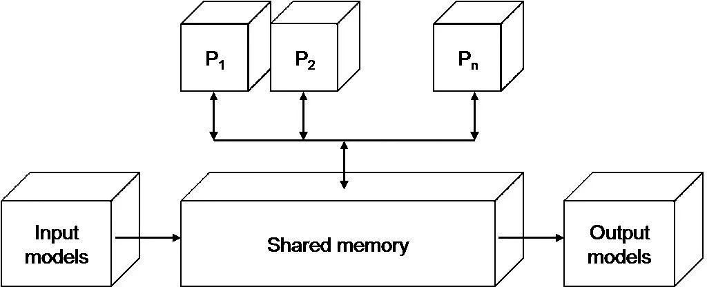
Figure 1:Block diagram of processors in a simulation system.
6 The program application created by MPI
The MPIfacilitatesthisapproachby providingmany wrappersfor callstoindustrialstrength open source MPI implementations such as MPICH and LAM-MPI.The applying standard parallel processing techniques and Message Passing Interface(MPI)implementations are used.Their applications can benefit the advantages of parallel computing[Raeth(2010)].
The abovementioned system affects the multiprocessing program code.Distributed architecture was realized as connection of five nodes(one is a central computer,the others are computing nodes),see Fig.2.One node(N1)is designed as a central computer and the others are computing ones and each of them is calculating only one mathematical model.As it results from the expression,the mathematical model defined by Eq.17A11∗x1is simulated by theN2computer on the second node,Eq.18A12∗x2is simulated by theN3computer on the third node,the mathematical model defined by Eq.23A21∗x1is simulated by theN4computer on the fourth node resp.Eq.24A22∗x2is simulated by theN5computer on the fifth node.
Functions send/receive commands are implemented to change messages in the source code application and are added to run in the nodes.We use two basic functions to send and receive messages[Mpich2(2008)]:
•MPI_Send(parameters)
•MPI_Recv(parameters),
Where the MPI_Send()function on a side of the sender is responsible for sending messages.The corresponding MPI_Recv()function is inserted into a target process to receive messages.
The simulation takes 25 seconds and the intermediate data is sent in periodical time to the node that presents the received data in a graphical form.The simulation time is set depending on the integration error value that is less than 0.002 in distributed simulation methods.
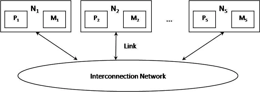
Figure 2:Message passing interface–architecture,Ni–node-computer,Pi–processor,Mi–local memory,Huges(2003).
7 The distributed methods
7.1 Computation using the MPI tool
The parallel system based on the standard MPI can be introduced as the first one.The MPI is a library specification for message passing.Message passing systems provide alternative methods for communication and movement of data among multiprocessors.Typically it combines local memory and the processor at each node of the interconnection network.There is no global memory,it is necessary to move data from one local memory to another by means of message passing,see Chevance(2005).
There arennodes which consist of a processorPand a local memoryM.N-odes communicate with each other by means of links and via an interconnection network.In executing a given program,the program is divided into concurrent processes,each is executed in a separate processor.This simultaneous execution of the same task in multiple processors is used in order to obtain results faster.
The implementation MPICH2 is a portable,high-performance implementation of the entire MPI-2 standard and consists of a library of routines that can be called from the program.The TOOLKIT is an integrated suite of tools that supports measurement,analysis,attribution,and presentation of application performance for both sequential and parallel programs[Adhianto,Banerjee,Fagan,Krentel,Marin,Mellor-Crummey,and Tallent(2010)].
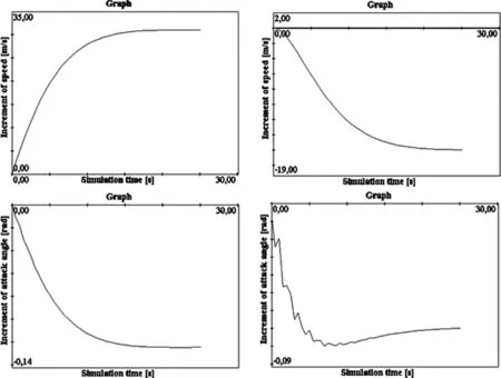
Figure 3:Simulation results of Eq.17–upper left,18–upper right,23–bottom left,24–bottom right.
From the graphical output of the central node,we obtain Fig.3 as a result of the simulation.The simulation of a mathematical model using a cluster technology of a flight simulator is done according to the Eq.17 and 18 or 23 and 24.
The upper left picture shows the speed increment depending on the fuel supply and it is equal to 31.0192[m/s].The upper right picture shows the speed increment depending on the elevator and it is equal to−15.6142[m/s].The bottom left picture shows the increment of the angle of attack depending on the fuel supply and it is equal to−0.1237[rad].The bottom right picture shows the increment of the angle of attack depending on the elevator and it is equal to−0.0714[rad].
7.2 Computation using the OpenMP tool
Shared memory computing is based on multi-core processors that can issue multiple instructions per cycle from multiple instruction streams,El-Rewini,Abd-El-Barr(2005).The same simulation problem described above was also realized on the SM based on the OpenMP standard that supports multi-platform SM parallel programming in C/C++.
The presented OpenMP based system is modelled on a computer that consists of Intel Quad Core Q9450 processor with 4 cores,2.66 GHz each.Informative simulation results are shown in Fig.4.
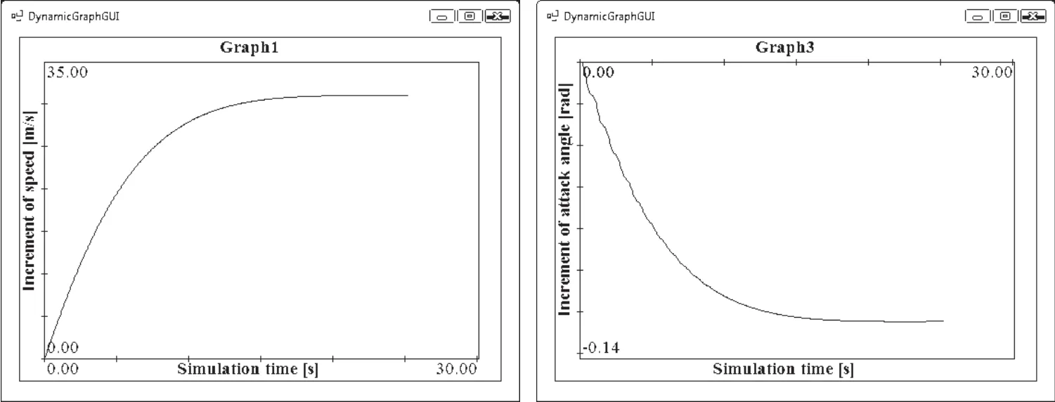
Figure 4:Simulation results of Eq.17–left,23–right.
The left picture shows the speed increment depending on the fuel supply and it is equal to 31.0174[m/s].The right picture shows the increment of an angle of attack depending on the fuel supply and it is equal to−0.1247[rad].The graphical presentation of a speed increment depending on the elevator is identical to the presentation in the Fig.3,top right.A steady state of the speed increment is 15.6134[m/s].The graphical presentation of the increment of the angle of attack depending on the elevator is identical to the presentation in the Fig.3,bottom right.A steady state of the increment the angle of attack is−0.0721[rad].
7.3 The hybrid distributed shared memory architecture
The hybrid distributed-shared memory system combines the advantages of architectures mentioned above.Each node consists of two processor cores.
Two nodes compute four independent mathematical models according to Eq.17,18,23 and 24.The third node collects computed data from other nodes and shows the simulation results in a graphical form.Each computing node consists of Athlon X2 processor with two cores that share one memory.The core frequency is 2.6 GHz and the memory size is 2 GB.All nodes are interconnected via 1 Gbit/s Ethernet.Graphical results represent their compatibility with previous forms of simulation and are shown in Fig.5.The upper left picture shows the increment of speed depending on the fuel supply:it is equal to 31.0178[m/s].The upper right picture shows the increment of speed depending on the elevator:it is equal to−15.6151[m/s].The bottom left picture shows the increment of the angle of attack depending on the fuel supply:it is equal to−0.1248[rad].The bottom right picture shows the increment of the angle of attack depending on the elevator:it is equal to−0.0705[rad].
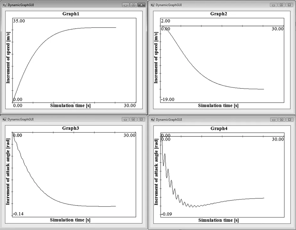
Figure 5:Screenshot of simulation results based on Eq.17–upper left,18–upper right,23–bottom left,24–bottom right.
8 Summary
The paper introduces three main architectures for efficient simulation of mathematical models:the DM,the SM and the hybrid one.The simulation is implemented on known different architectures that support parallel computing.This helps to overcome physical and architectural limitations of computational power that can be achieved with a single-processor system.
The use of a processor,a faster cache memory,operating memory access and a higher transmission capacity are then very suitable for the application.The hybrid architecture provides a higher transmission capacity and higher speed of computation.
Modelling of a parallel aspect of decomposed subsystems of a flight simulator in a form of a mathematical notation was carried out in accordance with Eq.17,18,23 and 24.The results achieved in computation of mathematical models and the use of these three methods seem to be effective and pragmatic according to the results of from an integration algorithm.
The general accuracy from the comparison of simulation results of the use of the three methods is shown in Tab.1,resulting in the accuracy less than 0.002.

Table 1:Accuracy of simulation results.
The strengths of the three models are also a combination of both the advantages:efficiency(memory savings)and ease of programming of a shared-memory method and scalability of a distributed-memory method.Sometimes we might get an advantage of faster simulation,but often on account of a defined quality.Generally,it is also possible to run a program faster because of such factors as availability of a better bandwidth for intra-node communication that provides extra communication with the MPI across nodes.These facts and accuracy are very good for real-time simulation.
Acknowledgement:This work was supported by the Slovak Grant Agency for Science,by the VEGA 4/0330/09 grant.
Adhianto,L.;Banerjee,S.;Fagan,M.;Krentel,M.;Marin,G.;Mellor-Crummey,J.,and Tallent,N.R.(2010):HPCTOOLKIT:tools for performance analysis of optimized parallel programs.Concurrency Computat.:Pract.Exper.,vol.22,pp.685–701.doi:10.1002/cpe.1553.
Blakelock,J.H.(1991):Automatic control of aircraft and Missiles.Second Edition,John Wileyamp;Sons.Inc.,New York.
Bajborodin,J.V.(1975):Bortovyje sistemy upravlenja poletom.Transport,Moskva.
Cellier,F.,E.;Kofman,E.(2006):Continuous System Simulation.Basic Principles of Numerical Integation:New York:Springer,vol.2,pp.25–32.
Clark,R.N.(1996):Control System Dynamics.First Ed.,Cambirdge University Press,New York,USA.
Duncan,S.H.;Gordon,P.L.;Zaluska,E.J.;Edwards,S.I.(1994):Parallel processing in high integrity aircraft engine control.Springer-Verlag,Berlin.
El-Rewini,H.;Abd-El-Barr,M.(2005):Advanced Computer Architecture and Parallel Processing.John Wileyamp;Sons,Inc.,New York.
(2002):Tools for creating of multimodels.Kybernetes:The International Journal of Systemsamp;Cybernetics,vol.9,pp.1391–1400.
Huges,C.;Huges,T.(2003):Parallel and Distributed Programming UsingC++.The Safari Press,Addison-Wesley Professional.
Chapman,B.;Jost,G.;Van der Pas,R.(2007):Using OpenMP–Portable Shared Memory Parallel Programming.The MIT Press,Massachusetts.
Chevance,R.J.(2005):Server Architectures:Symetrical Multiprocessors.Elsevier,Digital Press.
Krasovskij,A.A.(1950):Sistemy avtomaticeskogo upravlenja poletom i ich analiticeskoje konstruirovanie,Nauka,Moskva.
Kvasnica,P.;Páleník,T.;,M.(2007):Mathematical model of aircraft and its visualization using MPI.Proceedings of 3rdInternational Workshop on Grid Computing for Complex Problems,GCCP Bratislava,pp.117–125.
(2007):Modeling characteristics of the aircraft control.First Ed.Technical University of Košice.
Martincová,P.;Grondžák,K.;Zábovský,M.(2008):Programming in kernel of operating system Linux.First Ed.University of Žilina.
McCormic,B.W.(1995):Aerodynamics,Aeronautics and Flight Mechanics.John Wileyamp;Sons,Inc.,New York,Second Ed.,USA.
Mmpich2(2009): MPICH2 is a high performance and widely portable implementation of the Message Passing Interface(MPI)standard.[Online].Available:http://www.mcs.anl.gov/mpi/mpich2.
Raeth P.G.(2010):Parallel MATLAB using standard MPI implementations.Proceedings of High Performance Computing Modernization Program Users Group Conference(HPCMP–UGC),2010 DoD,pp.438–441.
Rolfe J.M.;Staples K.J.(1986):Flight Simulation.Cambridge University Press,Cambridge.
Tereshenko V.(2009):One tool for building visual models.Proceedings of Computational Intelligence,Modelling and Simulation,2009.CSSim’09.International Conference on Brno,pp.59–62.
1Regional Department for Environmental Issues of Trencin,Hviezdoslavova 3,911 00,Slovak Republic.tel:+421-32-7432032,e-mail:kvasnica.igor@gmail.com.
2Alexander Dubcek University of Trencin,Faculty of Defense Technology,Departmentof Informatics,Študentská 2,911 50,Slovak Republic,+421-32-7400704,Fax:+421-32-7400102,Email:peter1.kvasnica@gmail.com.
杂志排行
Computer Modeling In Engineering&Sciences的其它文章
- Meshless Local Petrov-Galerkin and RBFs Collocation Methods for Solving 2D Fractional Klein-Kramers Dynamics Equation on Irregular Domains
- Kernel-Based Local Meshless Method for Solving Multi-Dimensional Wave Equations in Irregular Domain
- A High-Order Accurate Wavelet Method for Solving Three-Dimensional Poisson Problems
