On the Numerical Study of Capillary-driven Flow in a 3-D Microchannel Model
2015-12-13LeeandLee
C.T.Leeand C.C.Lee
On the Numerical Study of Capillary-driven Flow in a 3-D Microchannel Model
C.T.Lee1and C.C.Lee2
In this article,we demonstrate a numerical 3-D chip,and studied the capillary dynamics inside the microchannel.We applied the level set method on the Navier-Stokes equation which incorporates the surface tension and two-phase flow characteristics.We analyzed the capillary dynamics near the junction of two microchannels.Such a highlighting point is important that it not only can provide the information of interface behavior when fluids are made into a head-on collision,but also emphasize the idea for the design of the chip.In addition,we study the pressure distribution of the fluids at the junction.It is shown that the model can produce nearly 2000 Pa pressure difference to help push the water through the microchannel against the air.The nonlinear interaction between capillary flows is recorded.Such a nonlinear phenomenon,to our knowledge,occurs due to the surface tension takes action with the wetted wall boundaries in the channel and the nonlinear governing equations for capillary flow.
Microchannel,Navier-Stokes equation,Capillary flow,Finite element analysis,two-phase flow.
1 Introduction
Microfluidics system saw the importance of development of the bio-chip,which essentially is a miniaturized laboratory that can perform hundreds or thousands of simultaneous biochemical reactions.However,it is almost impossible to find any instrument to measure or detect the model,in particular,to comprehend the internal flow dynamics for the microchannel model,due to the model has been downsizing to a micro/nano-meter scale.No field of mathematics or physics seems to have had a greater influence and more obstacles to success than the numerical study of the micro-chip.
This article is mainly inspired by a an engineering application of microfluidic devices using capillary mechanism (see Fig.1,Fig.2).Microfluidics system with capillary action has shown a wide application across many disciplines such as chemistry,biology,bio-medicine,sensing and materials Beebe,Mensing,and Walker(2002).In manufacturing process,engineers often use photoresist JSR thin film,Poly-dimethylsiloxane (PDMS),or Poly-methyl methacrylate (PMMA)polymer as a substrate,then using coating,plasma treatment,lithograph method and CO2 machining to carve the channel and cool down the heat of the material Giordano and Cheng (2001);Bubendorfer,Lui,and Ellis (2007);Lee and Lee (2012).Fig.2 illustrates the pattern structure of a capillary microchip model drawn by AUTOCAD and Fig.1 demonstrate the finished laboratory work using PDMS and lithography.
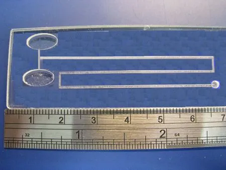
Figure 1:Engineering model of capillary-driven model chip.The experimental equipment and finished work was carried out using coating,plasma treatmen,laser machinning and CO2 cooling technique.

Figure 2:Schematic diagram of capillary microchannel model.The pattern design usually is the first stage of fabrication procedure in engineering application using AUTOCAD.
It is important to note that authough the issue of reducing the size of microfluidic chip to a scale of micro-meters is in progress in Engineering development,the analysis of flow dynamics such as pressure variation,stream field distribution and advancement of meniscus water front also is faced with the difficulty of the task.In general,the engineers have to set up the high resolution Charge Coupled Device(CCD)and high-speed camera to visualize the capillary flow in microfluidics devices,but often finds difficult getting into the capillary dynamics such as stream field,driving velocity of flow and pressure gradient in microchannel.As far as we know,capillary is naturally influenced by the surface tension force against the liquid and wall of the channel in which the liquid will be soaked up according to adhesion and cohesion forces between molecules Washburn (1921).Hence,to study the capillary action and flows inside the microchannel,it is important to pay attention to the surface tension and wall adhesive forces which are often used to transport fluids through microchannels in Micro-Electro-Mechanical-System (MEMS)devices or to transport a small amounts of fluid using micropipettes Beebe,Mensing,and Walker (2002).Cases of multiphase flow phenomena in a porous medium such as oil,and droplets on solid walls are typical examples where wall adhesion and surface tension strongly influence the dynamics of the flow Tornberg and Enhquist(2000).A numerical study of multi-phase granular materials based upon micro-mechanical modelling is proposed.Discrete element simulations are used to investigate capillary induced effects on the friction properties of a granular assembly in the pendular regime Scholtes,Chareyre,Nicot,and Darve (2009).Since in recent years,the technology of fabricating channels at the length of micron scale has made huge progress,it not only makes a fruitful development in MEMS but also finds wide applications in other engineering applications,e.g.,the diagnostic testing and DNA analysis and as micro-reactors.In practice,when a surface of substrate undergoes some engineering modifications such as coating,and plasma treatment,it can easily gain specific properties such as zeta potential,hydrophilicity,contact angle,and adhesion on the substrates.For a surface that has primarily polar groups on it,such as hydroxyl groups,it will have a good affinity for water and build up strong adhesive forces with low contact angle on the substrate.Such a surface is called a hydrophilic surface.For a surface that is made up of non-polar groups,such as polymer materials or surface that are covered by organic layers,it is often referred to as a hydrophobic surface,and the contact angle with water will be large.The relationship of surface and molecule adhesion force is shown in Fig.3.
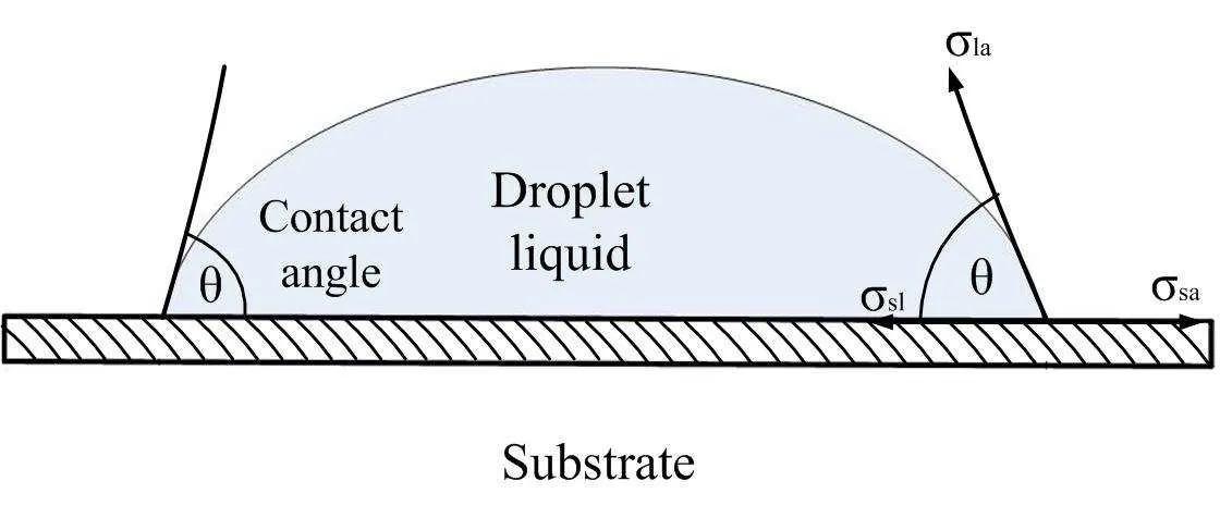
Figure 3:Diagram of the forces on molecules of a liquid.Surface tension forces acting on a droplet with solid/air/liquid interfaces indicates the physics mechanism of water bending over and being balanced on substrate.Balancing the tension forces with pressure will lead to the Young Laplace equation.
In the design abd fabrication of microchannels on hydrophilic surface,there are many ways to create the capillary flow on the substrates,for example,there have been a number of studies on capillary flows in micro-fabricated channels for microfluidic devices Kim,Xia,and Whitesides (1995);Kim and Whitesides (1997);Zhao,Moore,and Beebe (2001);Lin and Burs (2005);Lim,Kim,Yang,and Kim(2006).However,the numerical studiesof capillary flow behaviorin microchannels are still relatively scarce.Mason and Morrow Mason and Morrow (1994)examined the effects of lengthwise geometry on the mean interfacial curvature.Turian and Kessler Turian and Kessler(2000)studied a 1-dimensional(1-D)capillary-driven flow in a uniform but non-circular capillary tube.Erickson and Park Ericson,Li,and Park (2002)numerically studied the surface-tension driven,dynamic wetting flows in 2-dimensional(2-D)converging-diverging capillary tubes using finite element method.In a later work,Young Young (2004)constructed a formula of capillary meniscus interface movement along a horizontal 2-D pipe in a non-uniform capillary tube.The classical analysis of capillary phenomenon can be dated back to Washburn Washburn (1921).The capillary action in a sufficiently narrow tube of circular cross-section is described in Batchelor(1967).Theoretically,capillary flow can be understood via surface tension force which makes the surface to act as an elastic sheath to attach the liquid.This will minimize the surface area of liquid on it as well as minimize the energy of the fluid droplet on the channel.The surface tension is responsible for the pressure drop in the channel which not only produces driving forces,called capillary force,to push the liquid into the nonwetting surface,but also create a space to separate the two phases of liquid and air.The relationship between surface tension and pressure drop can be expressed by Laplace-Young equation which is a nonlinear differential equation that addresses the capillary pressure difference being sustained across the interface between two static fluids,e.g.,water and air,due to the action of surface tension or wall adhesion Batchelor(1967).Moreover,the Laplace-Young equation addresses that the pressure difference makes the shape of the surface of liquid and connects to wall boundary which is important in the study of static capillary surfaces.
In the present article,we propse a 3-dimensional(3-D)numerical model in micrometer scale and perform the numerical method on the model using finite element method.The Navier-Stokes equation incorporating with surface tension is adopted and finite element analysis and level set method are applied on the governing equations with characteristics of two-phase flow mechanism.In addition,the computational procedures for calculating the capillary-driven flow in a 3-D model are presented.The idea of emphasizing the flow dynamics in microchannels is that it is not only useful for important application regarding the design of biochip but also valuable for improvement on the weak point of the pattern structure during the fabrication of microchip.
The present model we studied is of micro-meter scale and rectangular.It is 3-D and the connecting channel is of T-shaped.The numerical 3-D microchip model comprises a shallow rectangular horizontal channel joining another vertical microchannel which are placed and attached to two reservoirs(inlets)that filled with water.The surface tension-driven,dynamic wetting phenomenon in microfluidic channels will be examined via finite-element method based on computational flow simulations.Because of the wall adhesion and surface tension at the air/water interface,water will freely and continuously flow through the designed microchannels and capillary action will take effect during the computation.In addition,we show the velocity fields,the pressure field and the shape and position of the water surface and across the channel model.
Our results show that capillary fluids will meet up and collide each other at the center of the interconnecting channel at the beginning and the interface will be bounced off at the bottom of the channel and make right-angled toward the horizontal microchannel.The molecules bounce off each other like colliding billiard balls,which is caused by both the action of gravity and surface tension that force the fluids to hold up onto the channel wall and being dragged along the boundary.The pressure distribution across the channel model shows that there is a pressure jump which accounts for 500-2000 Pa and is generated across the meniscus interface and the channel.Such a valuable information of pressure variation,caused by the surface tension,shows that liquids force the meniscus interace front to move through the microchannel by overcomming the gravity and flow resistance.
Finally,we compute the position of the interface/wall contact point by integrating the level set function along the microchannel length and find that there are two important phases on the curve needed to pay attention to.The first phase on the curve(t<500 µs)suggests that capillary water front was encountered with a strong resistance,which not only being receded from its previous position,but also was made sticky to the surface.After experiencing the first phase,the flow is able to overcome the surface tension and gravity and set off on a journey in microchannel.Such a phenomenon indicates that there is a strong nonlinear effect between the surface tension and wetted wall boundaries during the flow simulation.There is another phase shown on the curve which located between time t=3.5e-3 and 3.75e-3,shows that meniscus interface movement is again receding from its previous position,surface tension fails to push the fluid forward,and such a nonlinear phenomenon has never been detected by any laboratory instrument,nor have we reach a reasonable explanation.At the final time of the calculation,we observe the most higheset pressure variation that is generated is located at the downstream channel of the T-shape crossing microchannel model which accounts for about 2000 Pa.Such a pressure jump is reasonable and will break the realistic model in pratical laboratory chip Stroock,Dertinger,Ajdari,Mezic,Stone,and Whitesides (2002).In addition,to our surprise,there is a area of relatively high pressure difference generated on the center intersection of both the vertical and horizontal channel needs to pay attention which highlights a singularity point for numerical computation.
2 Chip model and definition
This paper demonstrates how to model the filling of capillary flow in a 3-D biochip.The present model consists of a horizontal rectangular channel of length of 5500µm and width of 500µm,connecting a vertical channel of length of 2500µm and width of 500µm.The vertical channel is attached to two water reservoirs(inlets)on both ends.All the channels and reservoirs are designed to have the same depth as 40µm.The plane geometry of the chip is illustrated in Fig.4.At the beginning,the thin channels are filled with air and water is filled up that flow freely and continuously into the reservoirs.Wall adhesion causes water to creep along the channel boundaries.The deformation of the water surface induces surface tension at the air/water interface,which create a pressure difference across the air/liquid interface.The pressure variations cause water and air to move along the channel and rightward in the downstream.The fluids continue to move straightforward due to the capillary force that overcomes the gravity force which becomes a major driving force in the capillary microchannel at the flow-front interface and builds up the water meniscus movement in the channel.In the present example,the capillary force has to dominate over the gravity throughout the simulation so that the fluids can flow without difficulty.Consequently,the interface moves along the designated channels during the entire simulations.
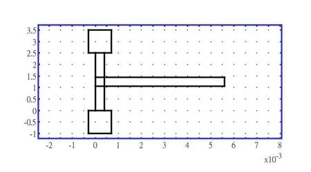
Figure 4:The geometry of 2-D planar scheme for numerical model chip.
3 Mathematical concept of capillary fluids
In the study of macro-scale flows,the interesting physics is often associated with high Reynolds number(Re)for the advancement of water front.However for flows in miniaturized channels,it is recognized to have low Reynolds number Purcell(1997).In microfluidic systems,inertia,which results in linear momentum transport equations as the governing equation for the flow motions,rarely plays an important role.In this regard,microchannel flows are taken as laminar,diffusiondominated and simple.From the viewpoint of capillary flow in microchannels,it involves a “two-phase”behavior where the two phases,air and liquid,are separated by a meniscus interface.To model the capillary flow in microchannels,one usually considers the liquids to be laminar,incompressible and two-phase.We also take into account of the surface tension for the liquids and set up the governing equation of convection of air/liquid interface by a level set function.Therefore the incompressible Navier-Stokes equations for two-phase flow which incorporate the surface tension should be given as Sussman,Smereka,and Osher(1994)

Here ρ denotes the density (kg/m3),η is the dynamic viscosity (Ns/m2),represents the velocity (m/s),pdenotes the pressure (Pa),and is the gravity vector (m/s2).Eq.(3)is called the advection equation,which is used to describe the transport of the fluid interface separating the two phases,air and liquid.Here φ is an implicit function which represents the interface between air and liquid.Eq. (3)is often coined as the level set equation and φ is the level set function.Here Fstis the surface tension force acting on the air/liquid interface,which is represented as

where I is the identity matrix,n is the interface normal vector,σ represents the surface tension coefficient (N/m),and δ is a Dirac delta function that is nonzero everywhere except at the fluid interface.In numerical computation,the delta function is often approximated by the following equation

and the interface normal is related to the set function φ as

The calculation of density and viscosity across the air/liquid interface is followed by

where ρair,ρwater,µairand µwaterare dimensionless parameters representing the densities and viscosities of the water and air respectively.These are used to smooth the density and velocity function across the meniscus interface and the numerical computation of the model.
Notice that we are particularly interested in flow of divergent-free velocity u in (3),i.e.,∇·u=0,since the equation is written in conservation law.For one-dimensional problem,the divergent-free condition implies that the velocity is constant.In numerical approach,any small perturbation will cause the problem and be advected with the velocity.Most of the numerical methods will introduce some artificial diffusion that will smear the profile during the computations.It means we have to stabilize the solution profile across the air/liquid interface in the direction normal to the interface.The stabilized advection can be expressed as follows Sussman,Fatemi,Smereka,and Osher(2005)

where ε is a parameter that determines the thickness of the interface,γ is the reinitialization parameter,u is the velocity vector of the liquid flow.
Eq. (10)is called the level set equation which is a nonlinear advection equation.In several space dimensions,the divergent-free velocity condition does not imply a constant velocity.The variations in the velocity will distort the shape of φ across the air/liquid interface.This implies that one might have to carefully choose γ in order to keep the profile of φ across the air/liquid interface in shape.Standard finite element method usually introduces the spatial stabilization technique to suppress spurious oscillations during the numerical computation.Therefore,in order to handle (10)numerically,we split the advection and stabilization procedures into a set of two partial differential equations (PDEs),namely,the advection of meniscus interface,

and the adjusted equation

for a steady state solution of φ .Here ε is a parameter that determines the thickness of the interface and γ is the re-initialization parameter.A suitable value for γ is the choice of maximum velocity magnitude for the model.In addition,one can also use an interface thickness of ε=hc/2 in the numerical computation wherehcis the characteristic mesh size in the region passed by the interface.Notice that the parameter γ determines the amount of reinitialization.The process of solving (12)to obtain a steady state solution of φ is referred to as the reinitialization procedure.Both the Eqs.(11)and (12)have to be solved initially for obtaining the convection of the profile φ,and then the time-dependent Navier-Stokes equations with surface tension (1),(2)will be followed to solve the computation of flow velocityuin the microchannel.
4 Surface tension analysis
Surface tension is a contractive tendency of the surface of a liquid that allows it to resist an external force.At liquid-air interfaces,surface tension results from the greater attraction of water molecules to each other (due to cohesion)than to the molecules in the air(due to adhesion).The net effect is an inward force at its surface that causes water to behave as if its surface were covered with a stretched elastic membrane.Because of the relatively high attraction of water molecules for each other,water has a high surface tension(72.8 milli-newtons per meter at 20 degree Celsius)compared to that of most other liquids.Surface tension is an important factor in the phenomenon of capillarity.
Surface tension has the dimension of force per unit length,or of energy per unit area.The two are equivalent–but when referring to energy per unit of area,people use the term surface energy–which is a more general term in the sense that it applies also to solids and not just liquids.For the study of force,surface tension of a liquid is one-half the force per unit length required to keep still a movable side of a frame over which the liquid is stretched.The cohesive forces among liquid molecules are responsible for the phenomenon of surface tension.In Fig.3,we see from the drop of a liquid,the molecules are being pulled equally in every direction by neighboring liquid molecules,resulting in a net force of zero.The molecules at the surface are being pulled inwards and do not have other molecules on all sides of them.This creates some internal pressure and forces that make the liquid surfaces to contract to the minimal area.In other words,surface tension is responsible for the shape of liquid droplet.In the absence of other forces,including gravity,drops of virtually all liquids would be approximately spherical.The spherical shape minimizes the necessary wall tension of the surface layer according to Laplace’s law.Another way of studying the surface tension is in terms of energy.A molecule in contact with neighboring molecules is in a lower state of energy than if it were alone (not in contact with a neighbor).For the liquid to minimize its energy state,the number of higher energy boundary molecules must be minimized.The minimized quantity of boundary molecules results in a minimal surface area.As a result of surface area minimization,a surface will assume the smoothest shape it can.
The capillary droplet in Fig.3 shows an analysis of surface tension on a solid surface at steady state.There are three surface forces,namely σla, σsl,and σsa,that act at the liquid/solid/air interfaces respectively and satisfy the Young’s law as Young (1805)

whereθ is the contact angle.Fig.5is the configuration of a capillary microchannel.The total surface energy of the capillary channel is composed of four parts.The first is the vacant area (AL-AX)multiplied by σsa.The second part is the wetting areaAXmultiplied by σsl.The third part is the surface energyE0stored in the filling reservoir.E0hardly changes due to the infinitesimal amount of liquid filling into the capillary.The fourth part is the complex surface of capillary meniscus front multiplied by σla.We neglect the fourth term because of the very small area of meniscus front compared to other surfaces.
Then the total energy in the capillary channel in Fig.5 is expressed as

If the cross-section of the capillary channel in Fig.5 is rectangular with a width of
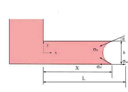
Figure 5:The mechanism of capillary-driven flow in microchannel model.The surface tension will pull the liquid in for a shpae of meniscus on all boundaies.
wand height ofh,the total energy can be expressed as

Taking the derivative of equation (14)with respect tox,we obtain the equivalent capillary forceFsapplied on the fluid column along thex-direction as

The pressure drop Δplaacross the liquid–air interface is therefore deduced under the assumption that channel heighthis much smaller than channel widthwYoung(2004):

Eq.(16)can be rewritten as the so-called “Laplace pressure drop”for the capillary tube by replacing the hydraulic radiusrh(=Dh/2=wh/(w+h))of the rectangular microchannel with the inner radius symbolrof capillary tube as

where σ is the liquid-air surface tension (force/unit length),θ is the contact angle,andris radius of micro-channel.
Eq. (16)or Laplace pressure (17)both demonstrate that the smaller the channel/capillary tube dimension,namely the larger the pressure drop across the liquidair capillary interface.For a water-filled glass microchannel in air at standard laboratory conditions,the surface tension is σla=0.0728N/m,ρ =1000 kg/m3,and θ=67.50in our numerical setting.
5 Finite element analysis
The finite elements to discretize the Navier-Stokes equations with surface tension(1)and (2).The convection equations of the capillary meniscus interface (10)and(11)play a key role in the numerical computation.Accordingly,we need to set up the weak form of the problem in our finite element analysis which means there is a basis for constructing the finite element solutions.The weak form of the problem is constructed by multiplying the differential equations with test functions which are fixed at boundaries with zero and the governing equations are integrated over the domain of consideration.For the problem with complex geometries,the adaptive grids in space and finite difference method in time are introduced.
For finite element analysis,we first define the finite-dimensional function space as follows

where Ω is the computational domain,∂Ω represents the boundary of Ω,and Λ is part of the boundary∂Ω where Dirichlet boundary conditions apply.
There is also a vector-valued function space defined as

The spatial finite element discretization of Eq.(3)is now formulated to find φ ∈Vh,such that

whereˇvis the normal vector on the boundary walls.Notice that if the boundaries are wetted walls,then u=0 and the last term in(20)vanishes.
The spatial discretization of the reinitialization (10)is to find φ ∈Vh,such that

wheref= γφ (1-φ).To avoid any unwanted flow crossing through the boundaries,we always set the boundary conditions to be zero.
The temporal discretization of the advection equation (20)is discretized using forward Euler method.Suppose φn= φ (tn)at time steptn,then an intermediate valuehas to be calculated first as follows:

In addition,an intermediate value of the normal vector of the interfacehas to be approximated at the same time by using the following equation

By considering (22)and (23),we use a second-order accurate discretization in time for(10)and start by choosingm=0 andso that form=1,2,...,we can determineaccording to the following equation

The iteration stops when

for some ζ.In this paper we set ζ=0.001to be as a tolerance error in our numerical approach so that we can finally setfor an updated value in (21).
Note that ε in (24)has to be carefully chosen.A very small ε compared to the grid sizehwill create over-or under-shoots for the steady state solution of(10).A suitable value of ε will result in a better conservation of bounded area by the 0.5 contour of the level set function in (10)and (11).In our numerical computation,we set ε=hc/2 wherehcis the characteristic mesh size in the region across the interface.
After updating the advection of φ from (24),we perform the finite element method on the incompressible Navier-Stokes equations with surface tension in (1)and (2).The spatial discretization of Navier-Stokes equations is proposed to find u∈Whandp∈Vhsuch that

and

Next,we need to pay attention to the approximation of the curvature and the gradient of φ in our computation.The first step is the approximation of (∇φ)n+1determined by the following equation

The mean curvature κn+1is then calculated by the following equation:


with

For next step,we define a pseudo un+1but with the pressure term implicitly,i.e.,we find un+1∈Wh,such that

In order to solve for an accurate un,the updated pressurepn+1is required,i.e.,we findpn+1∈Vh,such that

Finally,an updated un+1can be obtained to find un+1∈Wh,such that

The finite element method,which had established above,is relying heavily on procedures of solving the incompressible Navier-Stokes equations with surface tension and level set equation and can be summarized as follows:
1.Calculate the intermediate level set functionusing (22).
4.Calculate (∇φ)n+1from φn+1using (11).
5.Calculate κn+1using (29).
7.Calculatepn+1from (33).
8.Calculate un+1using (34).
6 Mesh generations
The computational subdomains for the chip model consist of two inlets,a vertical channel and a horizontal channel with depth of 40µm.The mesh divides subdomains into elements,and also divides boundaries into boundary elements.For the plannar 2-D geometry,the chip is divided into 6 subdomains,namely 2 inlet,2 short vertical channels,1 intersection region of crossing channels,and 1 long horizontal channel.We choose a mapped mesh consisting of quadrilateral elements.For each subdomain,the mapping algorithm defines a regular grid on a logical unit square and then maps it onto the real geometry using transfinite interpolation.We partition the subdomains into quadrilateral mesh elements.The schematic description of grids used in the 2-D geometry is illustrated in Fig.6.The boundaries are made up of straight lines.The sides of the quadrilaterals are called mesh edges,and their corners are mesh vertices.A mesh edge must not contain mesh vertices in its interior.The boundaries defined in the geometry are partitioned into mesh edges,referred to as boundary elements.The indications for all subdomains on the mesh statistics are shown in Table 1-4.The value in the minimum element quality specifies the minimum allowed element size,which by default is less than 1/10th of the maximum distance in the geometry.The element area ratio is defined as the minimal element area defined by the maximal element area.We note that the total number of mesh points is 700.The whole number of elements and boundary elements are 595 and 231 respectively.The total number of vertex elements is made up of 18.
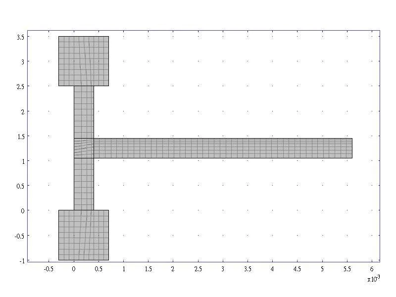
Figure 6:Mapped mesh structure for the chip in 2-D plan geometry.For each subdomain,the mapping algorithm defines a regular grid on a logical unit square and then maps it onto the real geometry using transfinite interpolation.
In mapped mesh technique,we need to control the mesh density on some flow channels by specifying a constrained edge element distribution on subdomains 3,5 and 6.This is when we want to force a specific edge-element distribution on a boundary segment.In subdomains 3&5,the number of edge element is 4 on the short edge of the rectangular channel.The element ratio is 3,which dictates the ratio in size between the last element and first element along the edge.The element distribution method is linear and we apply the reverse direction technique to let the distribution be defined in the opposite edge direction.In subdomain 6,the number of edge element is 7 on the short edge of the rectangular channel.The element ratio is 3,together with the distribution method being linear and the reverse direction is also applied to let the distribution be defined in the opposite edge direction.
It is our goal to create a 3-D mesh by extruding a 2-D mesh to create a hexahedral mesh.The corresponding 3-D mesh generations for the geometry of numerical chip is shown in Fig.7.On the geometry extrusion,the element layer distribution is linear,we specify an element layer by a vertical distance of 40e-6(40 µm),which is a resulting mesh extrusion for 3-D.
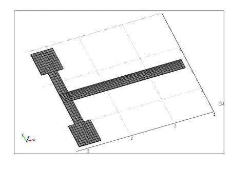
Figure 7:Mapped grids of 3-D meshes of the capillary chip.This is created by extruding the 2-D mesh using 40µm in the z-direction.

Table 1:Mesh statistics for subdomains 1&2.

Table 2:Mesh statistics for subdomains 3&5.

Table 3:Mesh statistics for subdomain 4.

Table 4:Global mesh statistics for subdomain 6.
7 Initial and boundary conditions
Navier-Stokes equations with surface tension (1),(2)describe the transport of the mass and momentum for fluids in microchannels.In addition,Eq. (3)describes a time-dependent equation for an implicit profile function φ which represents the interface and its evolution with time.
In our numerical approach,φ has to be initiated att=0.One way to set the initial condition for φ is by a signed distance function which represents the density and viscosity discontinuities over the interface Olsson and Kreiss (2005).In numerical computations,we assign the interface between the air and liquid to as the 0.5 contour of φ where in air φ =0 and in liquid,φ =1.As a result,a smeared-out Heaviside step function is used to describe φ as 0≤φ≤0.5 in one phase and 0.5<φ≤1 for another phase so as to smooth the transition across the interface.It is represented as

Initially,the reservoirs are continuously filled up with water while the capillary channels are filled with air.The initial velocity is set to zero.
8 Inlet
The hydrostatic pressure,p=ρgH,gives the pressure at the inflow boundary.HereHrepresents the depth of the chip model.In addition,we assume water enters through the inlet continuously to fill up the reservoir so that the level set function in this area is always set as φ=1.
9 Outlet
At the outlet,the pressure is set equal to zero,that is,equal to the pressure at the top of the inflow boundary.Because it is an outflow boundary,one does not have to set any condition on the level set function φ.
10 Channel walls
The wetted wall boundary condition is required for the microchannel.It means the solid walls are in contact with the fluid interface.We set the velocity component normal to the wall to be zero,that is

and add a frictional boundary force as

where β is the slip length.The boundary condition also allows us to specify the contact angle θ ,that is,the angle between the wall and the fluid interface (see Fig.10.In our example,we set the contact angle as 67.50and the slip length equals the mesh element size.
11 Physics settings
The settings of physics constants used for the capillary model are shown in Table 5.
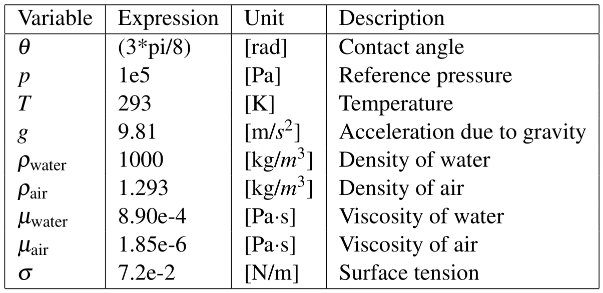
Table 5:The physics constants and variables for the capillary microchannel model.
12 Results and discussions
The planar structure for the chip model is illustrated in Fig.4.The angle between the wall and the fluid interface is called the contact angle and is shown in Fig.5.The geometric 2D meshes are depicted in Fig.6 where we have noted that we use the mapped mesh technique and a special setting on the constrained edge element.The detailed information for the 2-D mesh is described as follows.First,the mapping algorithm that we use defines a regular grid on a logical unit square and then maps it onto the real geometry using transfinite interpolation.We also apply a linear element distribution method on the grids and let the distribution be defined in the opposite edge direction afterwards to obtain a reverse,linearly distributed mapped mesh structure in the computational domains.In the two vertical channels,the number of edge element is set equal to 4,and the element ratio distribution is fixed at 3,while in the long horizontal channel,the element ratio of the distribution of constrained edge element is being set as 3 and the use of linear distribution in reverse direction is also applied as well.The detailed 2-D mesh settings for the chip are recorded in Table 1-4.
The establishment of 3-D meshes can be done by extruding the 2-D meshes up to 40 µm in z-direction (see Fig.7).Such an extrusion method consists of a total number of 595 hexahedra elements,1400 mesh points,1421 boundary elements for quadrilateral elements,together with a number of 480 edge elements.The initial development of the fluid interface in the numerical computations is shown in Fig.8.Here we point out that the capillary flow starts filling up the two inlets and a steadystate numerical solution has been obtained during this stage.The liquid surface was changed drastically in order to achieve a curvature with a contact angle as required.(Fig.9.The shape of the meniscus then is seen to attach the reservoirs and channel wall at the beginning of the calculation,then after being completely fulfilled with water in the reservoirs,the surface effect will come to effect to drive the liquids into the connecting microchannel(Fig.10).Note that due to the instantaneous start and action of capillary force,the surface tension effect of the channels and walls may oscillate and retrieve slightly during the capillary action(see Fig.17,t=0-7.5e-4 sec).
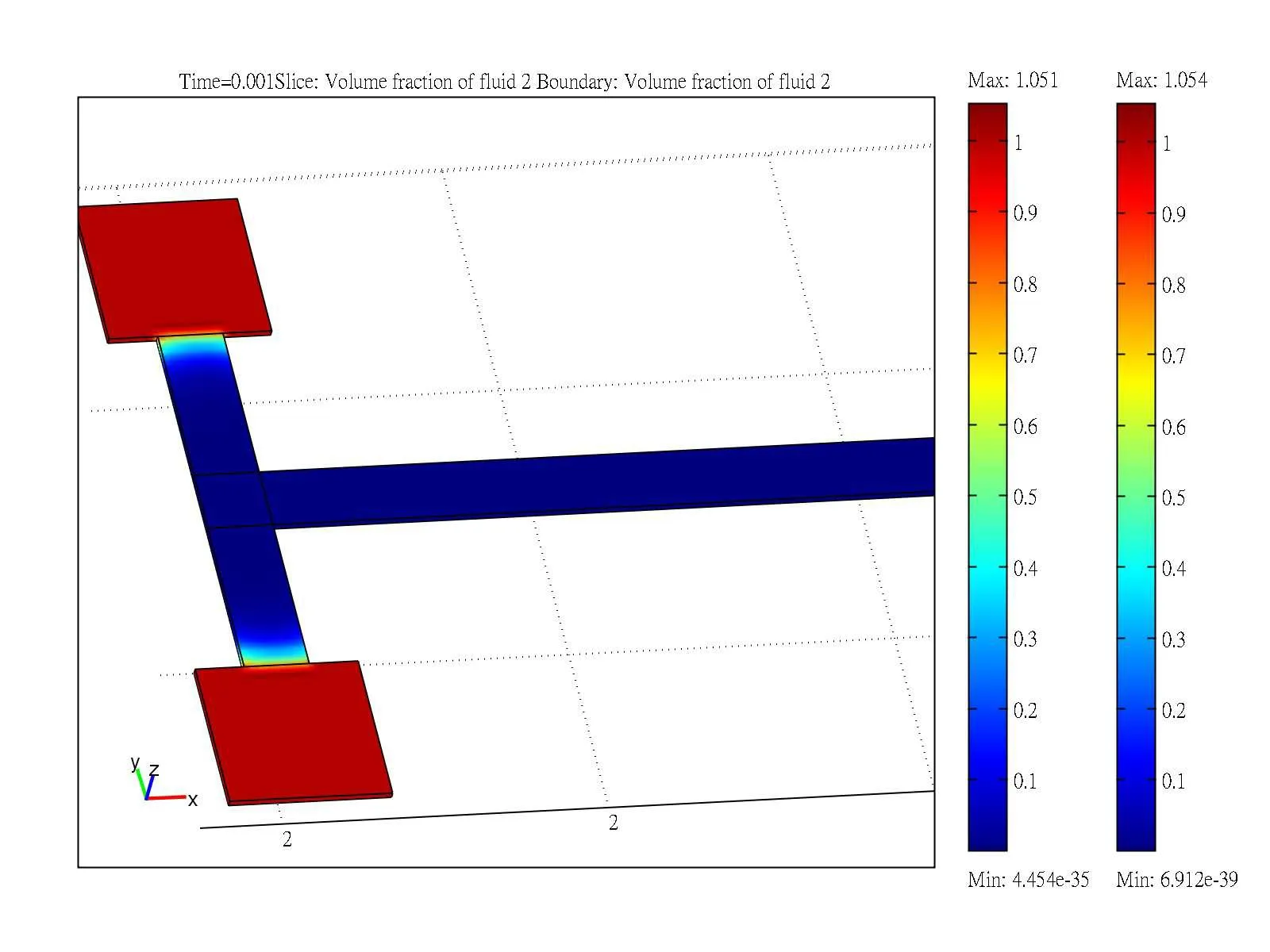
Figure 8:The initial development of fluid interface in the numerical computation.The water fulfills the inlet and air is stuffed in both the vertical and horizontal channels.The form of meniscus is formed and landed on the liquid/air interface.
The time evolution of the fluid interface is shown in Fig.11 where the two-phase flow in microchannel is recorded.Notice that when the initial state of the liquid is activated in inlets,this is a two-phase flow and surface tension will impose on the boundaries to make a curvature for flow and drag the water front through the microchannels.After the inlet was filled with liquid,the fluid front reaches the form of meniscus shape due to surface tension force in the channel.It is necessary to characterize the effect on the surface energetics and wettability during our numerical computation and the dynamic contact angle plays a key role in this case.The contact angle not only can be used to feature the forces on liquids but also can provide valuable information about surface adhesion as well as numerical computation.From the observation of Fig.11,the dynamic contact angle was present and in progress where the water front was seen dragged long and along the channel boundary,showing the driving force with surface tension is strong.Finally,the flows are managed to capture a designated contact angle of 67.50instantaneously during the numerical simulation.The contact line of the advancing meniscus in-terface has been maintained a curvature indicating the numerical calculation along microchannel is correct and reliable.
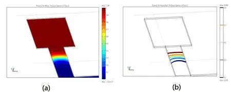
Figure 9:The advancing capillary flow at time t=2.5e-4,showing the shape of meniscus is form in the channel(a)flow volume (b)isosurface of the flow.The designated contact angle is formed showing the reliability of numerical computation.

Figure 10: (a).The diagram of 2-D microchannel,showing the surface tension force comes to effect to drive the liquids;(b).The diagram of 3-D microchannel model for surface tension force and flow direction to drive the liquids.
We are particularly interested in the interface and dynamics of flow at the intersection of two microchannels when two fluids make a head-on collision.Flow depicted in Fig.12 at t=8e-4 sec shows the volume fraction of two-phase flow approaching the intersection of both the connecting vertical and horizontal channels.The form of water/air interface at the junction point of the channels has been squeezed into an U shape and occurred at the center of the model channel.This is due to the pressure difference produced between the air and water inside the channel and strong reaction of surface tension for two phase flows.The corresponding streamlines at t=8e-4 sec are plotted in Fig.13.These are stream lines resulting from the vector field due to the surface tension and capillary effect of the flow.These are also lines that instantaneously tangent to the velocity vector of the flow.It is seen from the intersection of the T-shape channels,the streamlines gather symmetrically in the center of the channel and make turns to the right to continuously move forward.It is also observed that part of the flows will emerge from side the walls of the horizontal channel that merges with the other flows and bounces off the boundaries.In addition,we can see that when two fluids collide each other and make the drastic turn in the channel,the interface will be changed drastically,being squeezed up into a U-form and generating a high pressure difference around the center of two crossing channels(Fig.14).Such numerical results for capillary flow and interface dynamics are new and are reported here for the first time.
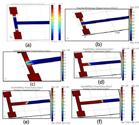
Figure 11:Capillary flow in the chip at time (a)t=2.5e-4 (b)t=6e-4 sec.(c)t=8e-4 sec.(d)t=0.002 sec.(e)t=0.0036 sec.(f)t=0.005 sec.
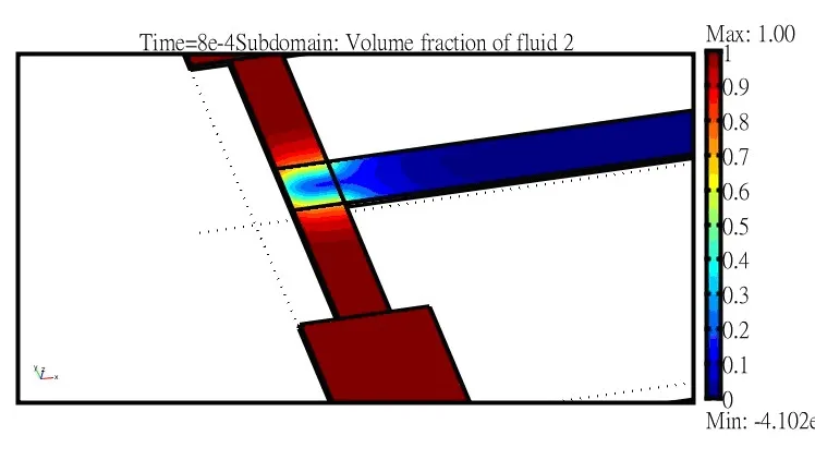
Figure 12:The depicted picture of water/air interface of two flows at the junction of channels at time t=8e-4 sec,showing the capillary flow behaviour across the intersection and is bended to make the turn along the channels.
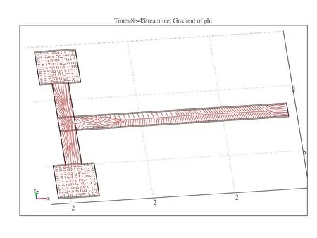
Figure 13:The streamline analysis for the flows at time t=8e-4 sec around the intersection of microchannels.
The vibrant red-colored velocity stream fields in Fig.15 highlighted the velocity field at time t=8e-4 sec.at the intersection of T-shaped crossing channels,where two flows from inlet are making a head-on collision and righ-angled turns.The results indicate that the maximum velocity is occurred and located at the center of the horizontal channel,featuring the largest velocity of advancing water front along the channel.This is mainly generated by surface tension and due to the symmetric geometry of numerical model where wave collisions are positioned near the corner of channels.
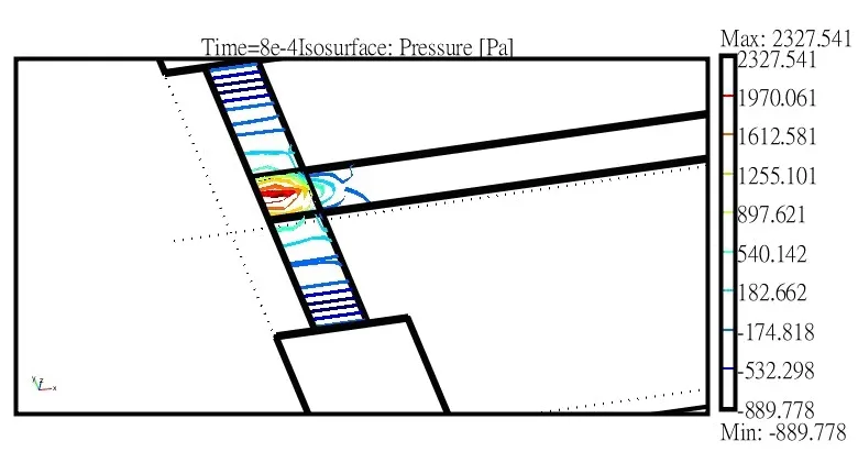
Figure 14:The iso-surface analysis of pressure distribution at time t=8e-4 at the junction of interconnecting microchannels of the chip.
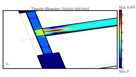
Figure 15:The velocity field at the time t=8e-4 sec,showing the colliding fluids under capillary action.
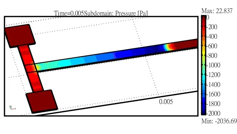
Figure 16:The pressure difference generated at time t=0.005 sec across the microchannel.The highest pressure drop generated in the model is accounted for 2000 Pa.
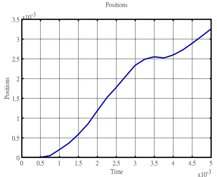
Figure 17:The positions of advancing meniscus interface as a function of time.It is integrated by the level set function with the wall contact point.
Fig.16 shows the surface plots of the pressure distribution across the numerical model at the final time of calculation.It is observed that there is a pressure variation of around 2000 Pa across the meniscus interface.The pressure jump in the channel is caused by the surface tension which also help force the water to overcome resistance and move along the channel against the air.It shows that the high pressure difference dominate the flow behaviour in the end in capillary channels.In addition,we calculate the position of the interface/wall contact point by integrating the level set function along the horizontal channel.Fig.17 shows the position of the meniscus contacting point as a function of time.The slight oscillations of the water front at time t=3.6e-3s should be highlighted the phenomenon that the meniscus interface will recede from its previous position before the surface action completely activated and taken control.This phenomenon also shows the nonlinear interaction between the surface tension and wetted wall boundaries.
13 Conclusions
We propose a 3-D numerical model for capillary flow and study the flow dynamics of meniscus interface including vector field,stream line distribution and pressure difference in channels.The dynamics and velocities of two colliding fluids collide near the junction of channels are studied.Both the pressure and positions of the capillary flow are examined through numerical computation.The streamlines and interface velocities are also illustrated.
The basic idea of designing the microfluidic chip is to provide more detailed information regarding the capillary flow dynamics in 3-D bio-chip.The capillary flow in a microchip is laminar,incompressible,and diffusion-dominated.In particular,it is two-phase,and surface-induced.We applied the level set method on the Navier-Stokes equations incorporating the surface tension with the aim of investigating the capillary dynamics.It is seen from the simulated results that the flow can produce nearly 2000 Pa in pressure difference across the model which help push the water through the designed channels through surface tension force.The whole model is solved by nonlinear Navier-Stokes equation incorporating with surface tension.The stream flow near the intersection of microchannels is first reported here for the first time.To our knowledge,this occurs because the governing equations of the capillary flow are highly nonlinear partial differential equations.
In numerical approach,the initial development of the fluid interface is obtained by solving nonlinear Navier-Stokes equations.The capillary flow starts filling upon the inlets and the surface tension make the water front to change drastically in order to obtain a contact angle against the wall.It is observed the capillary flow has the largest velocity value at the center line of the horizontal channel near the intersections.We also see two fluids make a head-on collision at the junction of two flow channels,creating a toppled U-shape interface form and generating a high pressure difference in the channels to drive the flow moving forward.Moreover the dynamic contact angle between liquids and walls has been observed and maintained during the computation,which characterizes the effect on the surface energy and wettability of the boundary condition.We also calculate the position of the meniscus interface/wall contact point by integrating the level set function along thin horizontal channel.The curve shows a slight oscillations indicating that the water front in microchannel will fall back a little bit with a short distance before it can kick off.Such a phenomenon shows the nonlinear interaction between the surface tension and wetted wall boundaries.From our viewpoints,Microfluidics system saw the development of the bio-chip,which essentially is a miniaturized laboratory that can perform hundreds or thousands of simultaneous biochemical reactions.However,no field of mathematics or physics seems to have had a greater influence and more obstacles to success than the numerical study of the microchip.It is understandable since the fabricated lab device has been downsized to a micro/nano-meter scale with no available instruments to measure or detect for the model itself,and an intriguing numerical computation will help emphasize the weak point of the chip and improve the fabrication procedure in the applications.
Batchelor,G.K.(1967):An Introduction to Fluid Dynamics.Cambridge University Press.
Beebe,D.J.;Mensing,G.A.;Walker,G.M.(2002):Physics and applications of microfluidics in biology.Annu.Rev.Biomed.Eng.,vol.4,pp.261–286.
Bubendorfer,A.;Lui,X.;Ellis,A.(2007): Microfabrication of PDMS microchannels using SU-8/PMMA moldings and their sealing to polystyrene substrate.Smart Mater.Struct.,vol.16,pp.367–371.
Ericson,D.;Li,D.;Park,C.B.(2002): Numerical simulations of capillarydriven flows in nonuniform cross-sectional capillaries.J.Colloid Interface Sci.,vol.250,pp.422–430.
Giordano,N.;Cheng,J.T.(2001):Microfluid mechanics:progress and opportunities.J.Phys.Condens.Matter.,vol.13,pp.271–295.
Kim,E.;Whitesides,G.M.(1997): Imbibition and flow of wetting liquids in non-circular capillaries.J.Phys.Chem.,vol.101,pp.855–863.
Kim,E.;Xia,Y.;Whitesides,G.M.(1995):Polymer microstructures formed by moldings in capillaries.Nature,vol.376,pp.581–584.
Lee,C.T.;Lee,C.C.(2012):A capillary-driven micromixer:idea and fabrication.J.Micromech.Microeng.,vol.22,pp.105034–105040.
Lim,Y.T.;Kim,S.J.;Yang,H.;Kim,E.(2006):Controlling the hydrophilicity of microchannels with bonding adhesives containing surfactants.J.Micromech.Microeng.,vol.16,pp.N9–N16.
Lin,R.;Burs,M.(2005): Surface-modified polyolefin microfluidic devices for liquid handling.J.Micromech.Microeng.,vol.15,pp.2156–2162.
Mason,G.;Morrow,N.R.(1994):Effect of contact angle on capillary displacement curvatures in pore throats formed by spheres.J.Colloid Interface Sci.,vol.168,pp.130–141.
Olsson,E.;Kreiss,G.A.(2005):A conservative level set method for two phase flow.J.Comp.Phys.,vol.210,pp.225–246.
Purcell,E.M.(1997):Life at low Reynolds number.Amer.J.Phys.,vol.45,pp.3–11.
Scholtes,L.;Chareyre,B.;Nicot,F.;Darve,F.(2009):Discrete Modelling of Capillary Mechanisms in Multi-Phase Granular Media.CMES:Computer Modeling in Engineering&Sciences,vol.52,no.3,pp.297–318.
Stroock,A.D.;Dertinger,S.K.W.;Ajdari,A.;Mezic,I.;Stone,H.A.;Whitesides,G.M.(2002): Chaotic mixer for microchannels.Science,vol.295,pp.647–651.
Sussman,M.;Fatemi,E.;Smereka,P.;Osher,S.(2005):An improved level set method for incompressible two-phase flows.Comp.Fluid,vol.27,pp.663–680.
Sussman,M.;Smereka,P.;Osher,S.(1994):A level set approach for computing solutions to incompressible two-phase flow.J.Comput.Phys.,vol.114,pp.146–159.
Tornberg,A.K.;Enhquist,B.(2000):A finite element based level set method for multiphase flow applications.Comput,Visual Sci.,vol.3,pp.93–101.
Turian,R.;Kessler,F.(2000):Capillary flow in a noncircular tube.AIChE J.,vol.46,pp.465–702.
Washburn,E.W.(1921):The dynamics of capillary flows.Phys.Rev.,vol.17,pp.273–282.
Young,T.(1805):An essay on the cohesion of fluids.Philosophical Transactions of the Royal Society of London,vol.95,pp.65–87.
Young,W.B.(2004):Analysis of capillary flows in non-uniform cross-sectional capillaries.Colloids Surf.A.Physicochem.Eng.Asp.,vol.234,pp.123–128.
Zhao,B.;Moore,J.S.;Beebe,D.J.(2001): Surface-driven liquid flow inside microchannels.Science,vol.291,pp.1023–1026.
1Mathematical Institute,University of Oxford,Woodstock Road,Oxford,OX2 6GG.
2Department of Chemistry,Simon Fraser University,British Columbia,BC,Canada.
