Intelligent Fuzzy Control Method in Gas Engine Governor
2015-11-25XiaoNingChenJunfengLuLiqiang
Xiao Ning Chen Junfeng Lu Liqiang
(1.School of Electrical and Information Engineering Beijing University of Civil Engineering and Architecture Beijing 100044 China 2.Research Institute of Petroleum Exploration &Development Beijing 100083 China 3.CNPC Great Wall Drilling Company Beijing 100101 China)
1 Introduction
Fuzzy control method develops rapidly and widely in the recent years.A great many of research institutions attach importance to this field all over the world[1-2].Fuzzy control method can solve complex and mutable conditions of industrial control systems,such as nonlinear,time-varying or uncertainty problems in system.As a result,intelligent fuzzy control is widely applied in domestic and abroad.As one of rapidly developed technology,it is successfully used in many fields[3-6],but in gas engine control system,the research is still relatively new.
The paper focuses attention on gas engine system research.Specially,the governor in this system should have high performance,since the engine is mainly used for power generation.It is required to keep stable velocity of engine when the load has any changes,and the error cannot exceed the given range.Therefore the paper does research on the system modeling and simulation,and fuzzy control method has been improved for precise speed control according to the characteristics of system operation.
2 Structure of gas engine system
Gas engine system includes engine,generator,governor,throttle,and so on.When the flywheel is running,speed sensor gets signals and sends them to test circuit.Then speed controller calculates and issues control instructions,and valve opening is changed through the driver and actuator.Finally,speed is stabilized at a constant value nearby,and intelligent control is realized.The structure of system is shown in Fig.1.

Fig.1 Structure of gas engine
3 Speed control system modeling of gas engine
The research uses MATLAB/Simulink simulation environment and applies Control system toolbox and Fuzzy toolbox[7].First,simulation models of subsystems are established,including speed controller,actuator,combustion dynamics,and so on.Then combining with subsystems,the whole gas engine system model is build.The most important research in this paper is speed controller.And several fuzzy intelligent algorithms will be compared and simulated.
3.1 Gas engine governor control model
Governor control model of gas engine system is shown in Fig.2.Just as we see,the system is a double-closed control loop.The outer loop captures real-time output velocity of dynamics unit and puts it into speed controller.Then compared with the set speed,the error is put into governor to calculate.The inner loop is actuator unit;valve opening is adjusted and controlled quickly by detecting the position of throttle in real time.
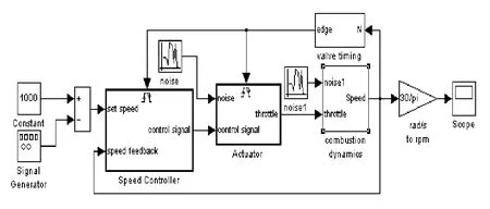
Fig.2 Gas engine governor control system model
3.2 Subsystem models of gas engine governor system
The actuator unit model is shown in Fig.3.It is a closed control loop.Input signal is the output of speed controller.After calculation,actuator gives the throttle a signal.
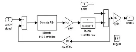
Fig.3 Actuator subsystem model
The model of gas engine dynamics unit includes dynamics subsystem and combustion subsystem.Fig.4 shows the model of dynamics unit,and Fig.5 shows gas engine combustion model.

Fig.4 Gas engine dynamics subsystem model

Fig.5 Gas combustion subsystem model
As shown in Fig.6,this subsystem is speed controller model.The speed control method is based on fuzzy intelligent control and PID control.The paper focuses attention to it-speed control algorithm.
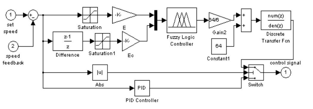
Fig.6 Intelligent speed controller model
4 Research and simulation ofintelligent speed control system
The gas engine is required to keep constant velocity output in respect that it is applied to power generation.Therefore,the main work is to research control method of engine in this section,including improving fuzzy control algorithm,combining with other control method and adding other algorithm.
4.1 Improved fuzzy control algorithm
Assumed that the controller is a double-input and single-output model,E and C represent deviation and deviation change rate respectively as input variables.U represents control output variable.Simple fuzzy control rule is represented as(1)

As we know,the rule of this controller is invariable when fuzzy control table is confirmed,which is difficult to obtain the desired effect for different controlled objects.The model and simulation result are shown in Fig.7 and Fig.8,respectively.
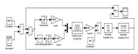
Fig.7 Single fuzzy control model
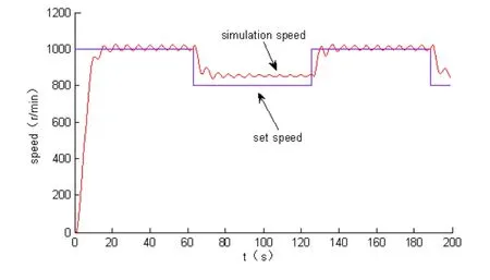
Fig.8 Simulation of single fuzzy control model
In order to improve the flexibility of adjustment,the rule increases a weighting factor a,it can present as(2)

When the absolute value of deviation E is bigger,the controller focuses on reducing the influence of E;when the value is smaller,main purpose of the controller is to restrain the overshoot quickly reached a plateau.
Accordingly,the rule of multiple weighting factors is formed,which can make system in a certain extent to fit nonlinear characteristics.For example,three grades are set by a1to a3,corresponding expression is as follows

Here,a1、a2、a3∈[0,1],a1<a2<a3.
The simulation model is shown in Fig.9.According to the size of error E,three grades are divided,namely a3=0.75,a2=0.6,a1=0.5.The system selects factors adjusted by the value of E automatically.
Fig.10 shows simulation result of multi-factor fuzzy control.

Fig.9 Multi-factor fuzzy control model

Fig.10 Simulation of multi-factor fuzzy control model
Compared with above two simulation figures,it is difficult to judge which one is better.So error square integral function is introduced for evaluating performance of the system,expressed as:

Calculation result shows that the value of single fuzzy control is 2.8e+003 and the value of multi-factor fuzzy control is 2.6e+003.It means the latter has better control performance;but as we seen,the system can not eliminate static error if only by increasing factors.
4.2 Multi-factor fuzzy PID control
Based on above problems,traditional PID control is combined with multi-factor fuzzy control,Simulink model is obtained in Fig.11 and simulation result is shown in Fig.12.
Obviously,the control effect is improved by introducing PID control.When error is bigger,fuzzy control can eliminate interference quickly;when error is smaller,PID control can guarantee no difference precise tracking.
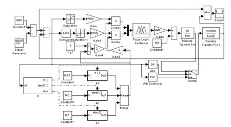
Fig.11 Multi-factor fuzzy PID control model

Fig.12 Simulation of multi-factor fuzzy PID control
Despite the control precision has greatly improved,but it is also seen that the system needs further improvement for several fluctuations when initial starting up,loading or unloading abruptly.
4.3 Repetitive compensation control with fuzzy PID compound control
As we know,neural network control,genetic algorithm and expert control can be applied to improve system performance;but these methods are more complex,needing a large number of experimental data for support,and in the actual operation,large computation and high ratio of CPU occupation require higher hardware design.The entire control time of system will not be guaranteed and it will be difficult to realize.
For practical control design,people hope the system has good tracking response,simple design and it is relatively easy to implement.Based on the above considerations,repetitive compensation control is introduced to the control algorithm after comparison[8].
The structure of repetitive compensation control is shown in Fig.13.A“past control deviation”,namely the last circle deviation is added to the controlled plant’s input besides the current error.The derivation is used repetitively.After several cycle of repetitive control,it can improve tracking precision and boost system performance.The method is not only applied for tracking input signal,but also inhibiting periodic interference.

Fig.13 Repetitive control system diagram
The simulation model added repetitive control is shown in Fig.14 and the simulation result is in Fig.15.
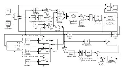
Fig.14 Repetitive compensation with fuzzy PID control system
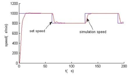
Fig.15 Simulation of compound control system
As we can see,at start-up time and sudden load or unload time,system tracking response is more rapid and the overshoot is smaller.It means repetitive compensation control plays an important role to improve the performance of this system.Moreover,it is easy and convenient to realize,which shows that this compound control method can be applied to gas engine operation control completely.
5 Conclusion
The paper firstly established subsystem mathematical models of gas engine and builded gas engine simulation system in Matlab/Simulink platform.Then improved fuzzy intelligent control method was put forward by adding weighting factors in the system.In order to reduce static deviation,improved fuzzy PID control model was established.On this basis,a repetitive compensation control algorithm was introduced and formed compound fuzzy PID control method in order to improve system performance.With the comparison of these control methods,compound control method made the system having more rapid tracking response and smaller overshoot.Further more,it was not complicated.That is to say,it is an effective intelligent control algorithm for the gas engine governor system.
Reference
[1]Li Shiyong.Fuzzy control,neural control and intelligent control theory[M].Harbin:Harbin Industrial University Press,1998.
[2]Dou Zhenzhong.Fuzzy logic control technology and application[M].Beijing:Beijing University of Aeronautics and Astronautics press,1995.
[3]Achiche Sofiane,Baron Luc,Balazinski Marek.predictive fuzzy control of paper quality[C].Annual Meeting of the North American Fuzzy Information Processing Society,Montreal,2006:31-34.
[4]Wai Rong jong,Lin Chin Min,Hsu Chun Fei.Direct fuzzy control for nonlinear servomechanism using adaptive tuning algorithm[C].Internation Journal of Computational Cognition,2013,1(11):79-103.
[5]Blahova L,Dvoran J.Neuro-fuzzy control of chemical technological process[C].17th International Conference on Process Control,Slovakia,2009:268-273.
[6]Wu Yanxiang,Zhang Chaojun,et at.Design and simulation of fuzzy-PID DC governor system based on mine hoist[C].2013 International Conference on Energy Research and Power Engineering,2013,341-342:834-838.
[7]Math works.Matlab user's guide7.x[G].USA,2007.Liu Jinkun,Advanced PID control-matlab simulation[M].2nd ed.Beijing:Electronic Industry Press,2004.
