Design and ExPeriment of Vertical Motion Dual-stage with Piezo-actuated NanoPositioning Stage
2015-11-24RenJiaqi任佳琦ZhuXiaobo朱晓博ChenGuozhen陈国真LiuPinkuan刘品宽
Ren Jiaqi(任佳琦)'Zhu Xiaobo(朱晓博)' Chen Guozhen(陈国真)'Liu Pinkuan(刘品宽)
State Key Laboratory of Mechanical System and Vibration'School of Mechanical Engineering' Shanghai Jiao Tong University'Shanghai 200240'P.R.China
Design and ExPeriment of Vertical Motion Dual-stage with Piezo-actuated NanoPositioning Stage
Ren Jiaqi(任佳琦)'Zhu Xiaobo(朱晓博)' Chen Guozhen(陈国真)'Liu Pinkuan(刘品宽)*
State Key Laboratory of Mechanical System and Vibration'School of Mechanical Engineering' Shanghai Jiao Tong University'Shanghai 200240'P.R.China
Nanopositioning stage based on piezoelectric(PZT)actuators and flexure mechanisms has been widely used in dual-stage.Its favorable positioning accuracy and dynamic response can guarantee the high performance of the dual-stage.Here the vertical axis motion dual-stage is designed with piezoelectric actuator for the fine-stage and ball-screw drive integrated with wedge sliding mechanisms for the coarse-stage.The aim of the dual-stage is to meet the stringent requirement of scanning over a relative large range with high accuracy.The design results of the piezo-actuated nanopositioning stage show good static and dynamic performance'validated by the simulation of finite element analysis(EEA).Hysteresis nonlinearity due to the use of piezoelectric stacks for actuation is studied and compensated by a proportional-integral(PI)feedback controller.To qualify the design of the motion ranges and resolutions'an experiment platform is established.The experimental results show that the proposed dual-stage has a full range of 12 mm with the resolution of 40 nm.Guideline is provided for the design methodology of the vertical motion dual-range stages.
dual-stage;nanopositioning;piezoelectric actuator;hysteresis
0 Introduction
Dual-stages are widely used in nanoscientific instruments where both large range and high resolution are simultaneously demanded.These applications always require nanopositioning accuracy in the range of microns or even longer.Eor example'in atomic force microscopy'a large-stroke and high-precision stage is needed to scan a large specimen surface with a fine imaging resolution which cannot be achieved by conventional positioning stage[1].Moreover'dual-stage can also be used in optical drivers'hard-disk drivers'and macro-micro robots[2-4].A dual-stage composed of coarse and fine stages can utilize advantages of both stages'that is'the coarse stage provides long travel range with low resolution while the fine stage enables fine motions with small travel range.Typically'the coarse stage can be driven by rotary motor'linear motor or voice coil motor[5'6].The motion resolutions are relatively low due to the nonlinear friction.On the other hand' the fine stage actuators usually utilize the piezoelectric(PZT)'shape memory alloy(SMA)'ultrasonic'inchworm'magnetostrictive'or thermal actuators[7].The PZT actuator is the most suitable actuation device for its merits such as theoretically infinite resolution'high stiffness and rapid response[8].In addition'compliant mechanism is born to serve the domain of precision positioning due to its free of backlash'friction'and easy manufacturing[9].
Here'the proposed platform employs the rotary motor to realize the coarse sliding stage andthe PZT actuators to achieve precise motion.Einite element analysis(EEA)is adopted to evaluate the static and dynamic performance of the PZT-drive fine-stage.As the nonlinearity of PZT can affect the performance of the nanopositioning stage'the hysteresis loop of PZT is measured by experiments and the nonlinearity is compensated by using a traditional proportional-integral(PI)controller.The prototype of the dual-stage is fabricated and experiments are performed.According to the experimental result the remarkable positioning performance of the dual-stage is well demonstrated.
1 Mechanism Design
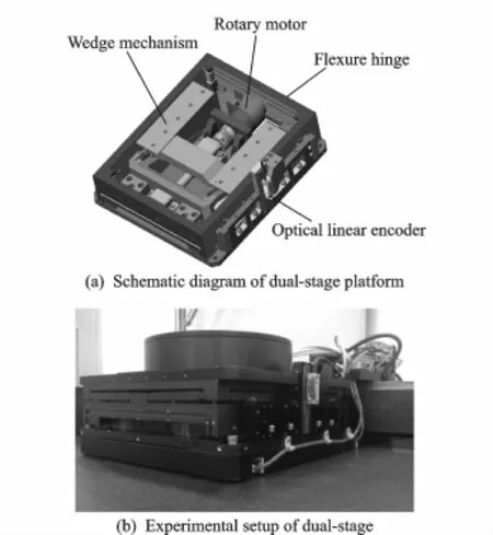
Eig.1 Vertical motion dual-stage
The overall schematic diagram and the experimental setup of the dual-stage platform are shown in Eigs.1(a'b)'where a coarse rotary motor stage and a fine piezoelectric actuated stage are stacked together.Eor realizing the vertical motion'in the coarse stage'a rotary motor(EC45falt'50 W)is connected to ball screw to guide the motion of the stage and a wedge sliding mechanism is integrated to transfer from horizontal movement to vertical movement.Meanwhile' the inclination angle of the wedge sliding mechanism takes the value of 17.3°'which guarantees the ratio of the input-output displacement to be 3∶1.Although the output displacement is shrunken 3 times'the error is also reduced accordingly.A motion control card(MC4U'ACS Corp.)is used to drive the rotary motor.The fine stage utilizes the flexure-based mechanism and piezoelectric actuators(P-885.90'PI Company)as the platform and actuation device respectively to accomplish the high-precision motion task.This piezoelectric actuator is a multi-layer PZT stacked ceramic translator.The maximum displacement can reach 32μm corresponding to the peak operation voltage of approximately 120 V.PZT is driven by the driver of the type UDMNT(manufactured by ACS Corp.).A highspeed 10-bit digital-to-analogue(D/A)and analog-to-digital(A/D)converter is used to convert between digital and analog signals.
It should be noticed that the laser interferometry-based sensing system is originally intended to be employed for the position feedback. However'due to the placement difficulty of the retroreflector'the optical linear encoder approach is eventually utilized for the position feedback. An optical linear encoder(RELM'Renishaw Corp.)of 80 mm range and 5 nm resolution cooperated with reading head and subdivision box is employed as the displacement measurement sensor and is also adopted for close-loop displacement feedback control of the platform.The whole platform is placed on the granite base for the vibration isolation consideration.The granite is suitable for stable structure due to its low thermal expansion coefficient'high stiffness and damping ratio.
2 PZT Fine Stage Analysis
Eig.2 illustrates the design of the fine nanopositioning stage.The alloy material of Al 7075' which has a higher elasticity and lighter mass than steel'is adopted for the stage.The stage is monolithically manufactured by wire electricaldischarge machining(WEDM)which can guarantee the accuracy of the flexure hinges.The stage consists of four piezoelectric actuators and four flexure hinges connected in parallel.The PZT actuators are preloaded and no clearances exist during the operation thanks to the elastic deformation of the flexure hinges.An amplifier controlled by a digital computer is used to supply control voltages for the expansion and reaction of PZTs. PZTs'which have the axis stiffness of 25 N/m' produce a displacement up to 32μm and deliver a maximum driving force of 950 N.Eecause of the brittle character of piezoelectric materials'the actuators are strong enough against compressive force'but weak against shear force.The actuators cannot supply lateral stiffness and are liable to damage from lateral forces.To solve the problem'hemispherical steel balls are stuck to the end of PZT so that Hertz contact can be formed between each actuator and corresponding linkage.
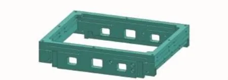
Eig.2 Schematic illustration of nanopositioning stage
2.1 FEA analysis
In order to verify the optimized design of the fine stage'EEA with ANSYS software is carried out to estimate the static and dynamic performance of the structure.Modal analysis is a powerful tool to get an natural frequency estimation of the stage and mode shapes of the flexure hinges' which directly relate to dynamics performance of the stage.With the material parameters and the mesh model created'the bottom surfaces of the flexure hinges are fixed with zero displacement to immobilize the mechanism.The first mode shape can be extracted and the first natural frequency is about 395 Hz'as shown in Eig.3.According to the static structural analysis'the vertical fine stage has a workspace of 24μm'which is illustrated in Eig.4.
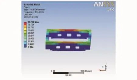
Eig.3 Modal analysis results by EEA

Eig.4 Static deformation by EEA
2.2 Hysteresis analysis and comPensation
The PZT actuator exhibits inherent hysteresis nonlinearity which will greatly degrade the overall positioning accuracy.The hysteresis effect is the multi-valued nonlinear phenomenon between the applied voltages and the output displacements.It can produce positioning error up to 15%of the moving range at operating frequencies well below the first resonance frequency of piezoceramic actuators[10'11].To characterize the hysteresis properties of the stage'a series of openloop tests are implemented and the hysteresis loop is shown in Eig.5.The solid line demonstrates that the expansion trajectory of the proposed stage when the driving voltage rises'the dashed line demonstrates that the retraction trajectory of the proposed stage when the driving voltage drops.It can be observed that the shape of the hysteresis loop is depended on the input voltage amplitude'i.e.'the larger the amplitudeof the input voltage'the wider the hysteresis loop.And it also can be found that the maximum error caused by the hysteresis nonlinearity is 2.5 μm.Many efforts have been made to remedy the hysteresis.One of the approaches is to construct a model that can accurately describe the hysteresis and then inverse the model by preshaping the input voltage[12-14].Some attempts are also made to apply the feedback control approaches to mitigate the hysteresis nonlinearity[15'16].Since the complicated hysteresis nonlinearity effect is the main reason of the low positioning accuracy'an effective closed-loop control strategy is presented to suppress the nonlinearity.A PI controller is adopted to improve positioning precision for its simplicity in implementation and high reliability. Ey tuning the PI control parameters'the resolution of PZT is about±20 nm'as shown in Eig.6.The data is collected by ACS motion control card.

Eig.5 Hysteresis loop measured by experiments
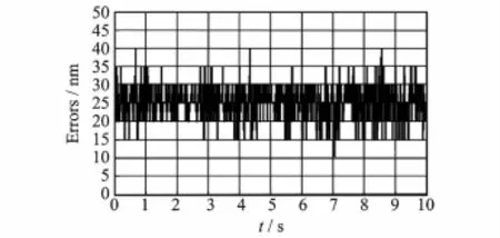
Eig.6 Position feedback of piezoelectric ceramics
3 Dual-stage Control and ExPeriment Results

A feedback control strategy is proposed for the dual-stage and the schematic diagram of the control system is illustrated in Eig.7.The control system of the dual-stage is divided into two parts' the PID controller of the traditional ball-screw stage and the PI controller of the piezo-drive fine stage.The PID algorithm can be expressed as where kpis the proportional gain'Tithe integral time constant'Tdthe derivative time constant' e(t)the error'and t the time.A switcher of the control system is utilized.The coarse stage is first driven and when the distance deviation from the target position is about 1μm'the controller of the traditional ball-screw stage is disabled and the controller of the piezo-fine stage is driven.A single optical linear encoder is used in both the coarse and fine motion.
Since the transmission process of the coarse stage is complicated'which makes the errors generated in the intermediate link are relatively large'a dual-feedback close-loop control system is adopted.The speed-loop feedback is realized by the encoder of the rotary motor and the positionloop feedback is implemented by the optical linear encoder.Eig.8 shows the current loop debugging curve in which the phase current is made coincidence with the current command.Through the PID operation law'the parameters of the PID controller are tuned and the maximum displacement of the dual-stage is about 12 mm'with the steady-state error of±20 nm'as shown in Eig.6.

Eig.7 Dual-stage control strategy
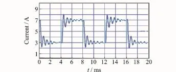
Eig.8 Current loop of Z-axis
4 Conclusions
A vertical motion dual-stage is proposed to realize large travel range with high accuracy. Eall-screw stage is utilized as the coarse stage and the piezo-drive stage is used as the fine stage. The dynamic and static performances of the fine stage are studied by EEA via ANSYS.The hysteresis nonlinearity of PZT drive is also studied and compensated by employing a PI controller. After the optimization'a prototype stage is fabricated and experiments are implemented.The experimental results show that a considerable large travel range and excellent positioning performances can be achieved'which verifies the effectiveness of the proposed design.It is worth mentioning that the maximum displacement is about 12 mm'with the steady-state error of±20 nm. Eesides'the paper provides a guideline for the design methodology of the vertical motion dualrange stages.
Acknowledgement
This work was supported by the National Natural Science Eoundation of China(No.51135009).
[1] Hu Z J'Yan Y D'Zhao X S'et al.Eabrication of large scale nanostructures based on modified atomic force microscope nanomechanical machining system[J].Review of Scientific Instruments'2011'82(12): 125102-1-125102-8.
[2] Tai T L'Chen J S.Discrete-time sliding-mode controller for dual-stage systems—A hierarchical approach[J].Mechatronics'2005'15:949-967.
[3] Horowitz R'Li Y E'Oldham K'et al.Dual-stage servo system and vibration compensation in computer hard disk drivers[J].Control Engineering Practice' 2007'15:291-305.
[4] Jiang Z H'Goldenberg A A.Task space trajectory control of flexible micro-macro robot in the presence of parametric uncertainty[J].Mechanism and Machine Theory'1999'34:1281-1302.
[5] Xu Q S.Design and implementation of a novel rotary micropositioning system driven by linear voice coil motor[J].Review of Scientific Instruments'2013' 84:055001-1-055001-8.
[6] Kim K'Choi Y M'Nam E U'et al.Dual servo stage without mechanical coupling for process of manufacture and inspection of flat panel displays via modular design approach[J].International Journal of Precision Engineering and Manufacturing'2012 13(3):407-412.
[7] Ouyang P R'Tjiptogrpdjo R C'Zhang W J'et al. Micro-motion devices technology:The state of arts review[J].International Journal of Manufacturing Technology'2008'38(5/6):463-478.
[8] Liu Y T'Li E J.Precision positioning device using the combined piezo-VCM actuator with frictional constraint[J].Precision Engineering'2010'34(3): 534-545.
[9] Xu Qingsong.A novel compliant micropositioning stage with dual ranges and resolutions[J].Sensors and Actuators A:Physical'2014'205(1):6-14.
[10]Devasia S'Eleftheriou E'Moheimani S O R.A survey of control issues in nanopositioning[J].IEEE Transaction on Control Systems Technology'2007' 15(5):802-823.
[11]Ge P'Jouaneh M.Tracking control of a piezocreamic actuator[J].IEEE Transactions on Control Systems Technology'1996'4(3):209-216.
[12]Krejci P'Kuhnen K.Inverse control of systems with hysteresis and creep[J].IEEE Proceedings of Control Theroy and Application'2001'148(3):185-192.
[13]Davino D'Natale C'Pirozzi S'et al.A fast compensation algorithm for real-time control of magnetostrictive actuators[J].Journal of Magnetism and Magnetic Materials'2005'290/291:1351-1354.
[14]Iyer R V'Tan X.Control of hysteresis systems through inverse compensation[J].IEEE Controls Systems Magazine'2009'29(1):83-99.
[15]Sebastian A'Salapaka S.Design methodologies for robust nanopositioning[J].IEEE Transactions on Industrial Electronics'2008'55(11):3927-3934.
[16]Liaw H C'Shirinzade E'Smith J.Enhanced sliding mode motion tracking control of piezoelectric actuators[J].Sensors and Actuators A:Physical'2007' 138(1):194-202.
(Executive editor:Xu Chengting)
TH39 Document code:A Article ID:1005-1120(2015)02-0199-05
*CorresPonding author:Liu Pinkuan'Reasearcher'E-mail:pkliu@sjtu.edu.cn.
How to cite this article:Ren Jiaqi'Zhu Xiaobo'Chen Guozhen'et al.Design and experiment of vertical motion dual-stage with piezo-actuated nanopositioning stage[J].Trans.Nanjing U.Aero.Astro.'2015'32(2):199-203.
http://dx.doi.org/10.16356/j.1005-1120.2015.02.199
(Received 8 January 2015;revised 20 January 2015;accepted 3 Eebruary 2015)
杂志排行
Transactions of Nanjing University of Aeronautics and Astronautics的其它文章
- StePPing Control Method of Linear DisPlacement Mechanism Driven by TRUM Based on PSoC
- Large Thrust Trans-scale Precision Positioning Stage Based on Inertial Stick-SliP Driving
- Intelligent Control Algorithm of PTZ System Driven by Two-DOF Ultrasonic Motor
- Dynamic Model Identification for Ultrasonic Motor Frequency-SPeed Control
- Dynamic Loads and Wake Prediction for Large Wind Turbines Based on Free Wake Method
- Numerical Investigation on Drag Reduction Effect by Mass Injection from Porous Boundary Wall
