Afterbody aerodynamic optimization design of transport airplane considering wing wake flow
2015-11-08BaiJunqiangSunZhiweiDongJianhongHuangJiangtao
Bai Junqiang,Sun Zhiwei,Dong Jianhong,Huang Jiangtao
(1.Northwestern Polytechnical University,Xi’an 710072,China;2.AVIC The First Aircraft Institue,Xi’an 710089,China)
0 Introduction
The technique of transport’s afterbody shape design for drag reduction has gained extensive attentionfrom most aircraft manufacturers[1-3].The drag amount of the afterbody is about 1/3 of the total drag of the transport[4].Flow separation will easily occur[1-4]for that the flow field is so complex under the influence of downwash,which will further cut down the safety and economy due to the structural oscillation of the afterbody[5].Hence the research on the design method of transport’s afterbody shape with consideration of flow separation and vortex-induction drag has been paid a lot of attention in many countries,which keep ahead in advanced aeronautical techniques.It is of great value in both theory and engineering to study the influence of afterbody shape on flow characteristics[6],which is the key technique of transport’s body design.Statistical results show that the drag could be reduced by about 0.5%-3%with a good design of the shape,hence remarkable economic benefit will be achieved.
The upswept angle,fineness,flatness and contraction ratio are several key design parameters in the shape design of the afterbody.Upswept angle mainly determines the flow field separation characteristics which directly relate to the pressure drag and structural oscillation.Most of these research works on optimizing the parameters in fuselage model or 2D configuration without the influence from other parts of the aircraft[6-7].However,when wing is a primary part to affect the flow field with downwash,they will have a great effect on the flow field and the optimized result.Therefore,in order to get the optimized afterbody shape in a whole aircraft model,a more refined optimization frame has to be carried out considering the wing wake flow.
The main difficulty in afterbody optimization lies on the parametric techniques and optimized frame to reduce the computational cost.In present analysis,a transport’s afterbody shape is optimized by a comprehensive optimization framework that has been established by integration of advanced surrogate model and geometric parameterization.Firstly,Free Form Deformation(FFD)technique is used for afterbody shape parametric model.Secondly,Kriging surrogate model is for aerodynamic characteristics approximation.Thirdly,infinite interpolation method is for spatial grid deformation.Finally,the afterbody optimization design result shows that the drag coefficient of wingbody configuration is reduced dramatically.
1 FFD parametric method
The FFD method,which integrates the deformed modeling method into traditional CAD/CAM system,was proposed in 1986 by Sederberg and Parry of Brigham Young University.It can provide the designers with more freedom in modifying the shape with deformation,and has a good property to ensure smoothness and continuity of the geometry.The algorithm assume that the object has good flexibility,which can be deformed easily under the action of external forces.
The procedures of FFD method to manipulate theobject’s geometry are as following:
(1)The first step is creating a deformation tool to define a control frame with control points lying on each of its edges and the local i-j-k as their identity,as shown in Figure 1.

Fig.1 Creating a deformation frame图1 构建变形框架
(2)The second step is calculating the original Cartesian coordinates of the research object’s control points and mapping the research object from the Cartesian coordinate system to parameter space.The parameter coordinates of the research object’s geometrical points in the parameter space should be calculated according to the local Cartesian coordinates.
(3)Modifying the deformation tool.The control points’original coordinates in the tensor product control body can be changed to get the new global coordinates,as shown in Figure 2.
The new Cartesian coordinates of the research object can be calculated by control points’new global coordinates and the local parameter coordinates of the research object in the constant parameter space,as Figure 3 shows.
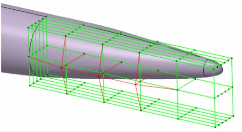
Fig.2 Modifying the deformation frame图2 修改控制框架
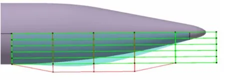
Fig.3 Calculate the new global coordinates图3 计算新全局坐标
In the FFD control frame,the axes of local coordinate system are along the directions of length,width and height.Assuming the control points are uniformly selected along each edge,then[8-9]
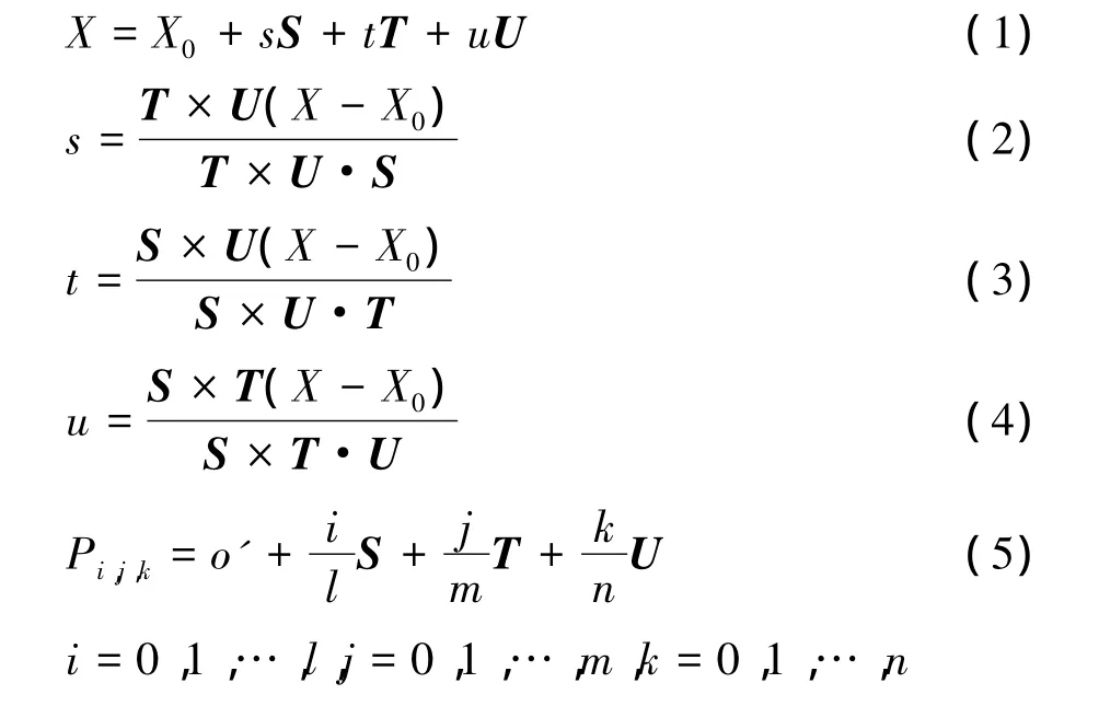
Where,X0( o')is the coordinate of the local coordinate system’s origin point in the Cartesian coordinates.X is the Cartesian coordinate of an arbitrary point inside the control frame,whose local coordinates are s,t,u separately.The value range of s,t,u is 0≤s,t,u≤1.S,T,U are the axis vectors of local coordinate system,and l+1,m+1,n+1 are the numbers of control points of the control frame along S,T,U directions.
Since the basis function of the FFD algorithm chosen in present analysis is NURBS function,the method has several geometric characteristics similar to NURBS surface,such as continuity,convex hull property and local approximation,therefore,this method is more suitable for afterbody geometry design compared to other methods.In addition,the FFD method will guarantee the derivation of an arbitrary order’s continuity and control the changing degree of volume.
2 Infinite interpolation deforming grid technique
In the application of aerodynamics optimization,the deforming grid technique is required for efficiency as the shape changing.In present work,grid-point-connecting multi-block structured grid is used to discretize computational domain.The number of control frames could be set hundreds or thousands when the shape is complex.The requirements of the deforming grid technique are as follows:
1)The capacity to express a new shape.
2)The high quality of grid.
3)Using parallel computing method to guarantee the efficiency.
4)Guarantee the characteristics of grid point connection.
In order to get a rational multi-block’s topological structure when the shape is changed,the volume spline interpolation technique is used to compute the deformation of block vertices.The technique is expressed as follows:

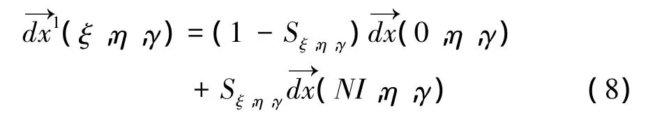
After the displacement is computed by volume spline interpolation technique,other grid points’coordinates in the block could be computed by transfinite interpolation(TFI)method[10], which includes three steps of iteration and has been widely used to achieve grid deformation.The first step is by linear interpolation to compute the inner displacement along theξdirection.
The second step is to superimpose the displacement to theηdirection
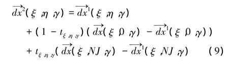
Similarly,along theγdirection

NI,NJ,NK are the dimensions of the grid points in the grid blocks.
The expression of Sξ,η,γis
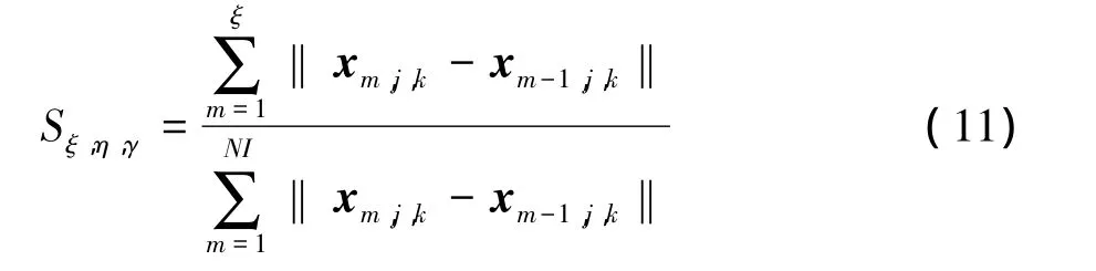
Similarly the tξ,η,γ,uξ,η,γcould be computed.Thus,the grid deformation(ξ,η,γ)=(ξ,η,γ)is achieved.
3 Flow field numerical simulation
The flow control equations are 3-dimensional compressible unsteady Navier-Stokes equations in an integral form.The expression in Cartesian coordinate system is

The turbulence model considered here is Menter’s k-ω SSTmodel.For spatial discretion,3-order upwind MUSCL interpolation ROE scheme is used,together with multi-grid and parallel computing technique[11]. By comparing the numerical results with experimental results of DLR-F6 wing-body as shown in Figure 4,the CFD code used in this study is proved to be reliable.The computational condition is Ma∞=0.75,Re=3.0×10⁶
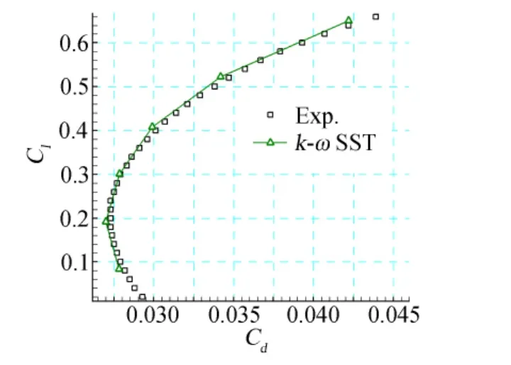
Fig.4 DLR-F6 wing-body lift-drag performance图4 DLR-F6升阻极曲线
4 Optimization framework
The modified particle swarm algorithm has been applied as the optimization method.Sun J and his fellows put forward the Quantum-Behaved Particle Swarm Optimization,namely the QPSO[12].It is different from SPSO that the searching pattern is along the track,the position of the searching particle is determined by the probability density function,which leads to a better global searching performance.The equation of the QPSO algorithm can be denoted as follows
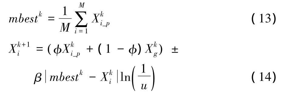
In the functions above,M is the number of particles of the swarm population,mbest is the average position of the pbest of each particle,φ,u are random numbers in(0,1),which are selected as the probability of both+50%and-50%,andβis the elastic coefficient as the control parameter in QPSO,with its value decreasing from 1.0 to 0.5 as the iteration continues.
As high accuracy surrogate model is the key technique for improving the efficiency of optimization design,the surrogate model used here is the modified Kriging surrogate model.Kriging surrogate model originates from the spatial statistics in geography.It is the unbiased estimation model whose estimating variance is the smallest.Kriging surrogate model has the characteristics of local approximation by the correlation function[13],can well predict the function value distribution at the unknown points.The relation of response and design variables can be denoted as the following equation in Kriging surrogate model,

Regressive model F(x)is the universal approximation of the design space.It is the certainty part,and can be divided into three categories:0 order(constant),1-order(linear)and 2-order(binomial).z(x)is a statistical random procedure whose average value is 0 and variance is σ2.Covariance of two interpolation points is,

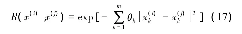
Where R is the correlation function of point x(i)and x(j).The Gaussian Function is used in present analysis and also in most applications,
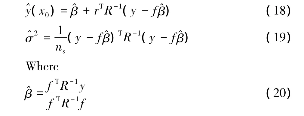
Therelated model parameterθkis determined by maximum similarity approximation,
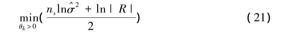
The related model parameter has great influence on the performance of the surrogate model.The traditional Kriging method solves the related parametersusing pattern searching method,which depends on the selection of the initial points and is easy to be trapped in the local optimum area.The standard particle swarm algorithm is used to optimize the related parameter of the Kriging surrogate model in order to improve the approximation[14].
For the reason that uniform designcan describe the sample space characteristics commendably and uniform samples have certain advantages in solving multi-level problem,the samples in present analysis are selected uniformly.the average relative error(ARE)is compared between the initial Kriging model and the modified Kriging model by PSO algorithm.
Table 1 shows that the average relative error of wing-body’s drag coefficient reduces 0.173123%after optimization and we can see from Figure 5 that the most optimized predicting values are closer to the CFD results than the values before optimization.

表1 ARE对比Tables 1 ARE comparing
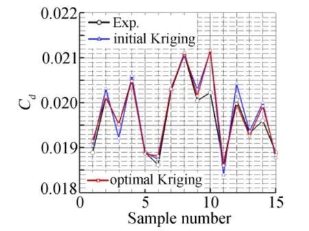
Fig.5 The predictive compare of test sample图5 测试样本预测对比
The loosening surrogate model management frame is employed in this optimization procedure[15].
5 Numerical results
In order to optimizea transport’s afterbody under wing interference in drag reduction,the designed afterbody shapes with and without wing interference are analyzed and compared.The grid is shown in Figure 6.Structured grid with 30 blocks in the total flow field has been used,and the grid number is 3 million.Parallel computing technique,Roe spatial discretion method,LU-SGSimplicit time advancing method,k-ω SST turbulence model and multi-grid accelerating technique are applied in the CFD calculation.The design status is:Ma∞=0.85,Re=1.0×10⁷,and CLis fixed to the value equal to cruise lift coefficient.
The optimization target is to reduce the drag by optimizing the configuration of afterbody at cruising status.Since the upswept angle would affect the tail down angle,a constraint is given for upswept angle to make sure it would not decrease.Considering the requirement of minimum space for capacity and body structure,the area of three sections are constrained to larger than specific value.
The optimization design problem could be denoted as below:
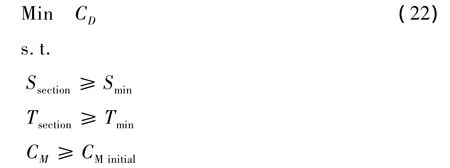
Tsectionconstraints of afterbody come from two places,as shown in Figure 7.One is the combination of floor and fuselage structure at the 78%length of the fuselage.The keel line of the fuselage must be lower than the plane of floor by 200 mm to save enough space for structure.The other is the cargo height,which must be higher than the initial height.S is the cross section area,and three cross section area is concerned at 70%,80%,90%length of the fuselage respectively.CMis the pitching moment constraint.All the constraints are added to the objective function by using linear penalty function.The objective function shows as follows

ωiis the weight of the CDand other constraints.From the function(23),it can be found that the constraints term would equal to zero when the constraints are satisfied,otherwise,the objective would increase.Figure 8 shows the control frame and the afterbody geometry.The control point of I0and J0move rigidly to ensure that the surface’s curvature between the middlebody and afterbody are continuous.K0and Kmaxmove along Z direction that can modify the crown line and the keel line of the airplane,and Jmaxpoint moves along Y direction that can modify the maximum half breadth shapes.
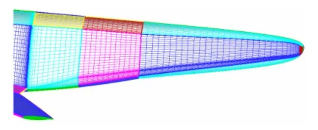
Fig.6 Grid图6 表面网格

Fig.7 Height constraints图7 高度约束

Fig.8 FFD control frame and afterbody geometry图8 FFD控制框架及后体几何外形
The parametric method is arbitrary spatial FFD approach.The geometry surface of afterbody is deformed by changing the FFD control frame vertices as introduced previously,then the geometry parameters of afterbody,such as the section shape and the upswept angle,would be modified.The optimization algorithm is the quantum particle swarm algorithm with a population of 90.The Latin hyper-cube method has been implemented in sample selection for establishment of the surrogate model.The total number of samples is 300.
With the Kriging surrogate model,the approximation error(%RMSE)of drag is 0.6%by crossed testification method.The optimization search is carried out for 60 generations,and the surrogate model is updated by CFD solver in every 10 generations.So the program calls updated geometry model for 6 times,and the CFD solver has been invoked 306 times.The total computational time is 734.4 machine-hours for computer with i7 3820 CPU and 8G RAM.
The body section area at 60%of fuselage length before and after the optimization is compared in the Figure 9.The initial body section is a dual circle shape,and the optimization result decreases the curvature variance gradient while the curvature radius is increased.The section shape is no longer a dual circle,which decreases the circumferential pressure gradient and destabilization of afterbody flow.

Fig.9 X/C=0.6 section shape comparison图9 X/C=0.6截面外形优化结果对比
The symmetry contour of the body is shown in Figure 10 with the comparison of with and without the wing interference.Because the local angle of attack of the body has been reduced by the downwash of the wing,the highest location of the symmetry contour under the wing interference is more ahead than that without wing interference.The bottom contour is lower than the result without effect of wing to reduce the pressure recovery gradient.
The pressure distributions of the plane of symmetry and plane at 60%of fuselage length are shown in Figure 11 and Figure 12,in which the decrease of the pressure recovery gradient after optimization can be clearly seen,and the pressure drag is reduced as a result.The cruising state aerodynamic characteristics before and after the optimization design are shown in table 2,in which the drag coefficient decreases by 6 counts and the liftdrag ratio increases by 3%,which is a great benefit in drag reduction.Cmis the pitching moment coefficient,which is slightly decreased to meet the constraint.From the limiting stream line on the afterbody in figure 13,we can see that the separation reduces to a small area,which would vanish if consider an APU system.
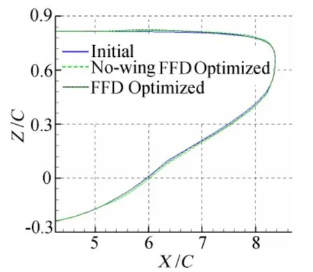
Fig.10 Afterbody symmetry contour图10 后体轮廓线
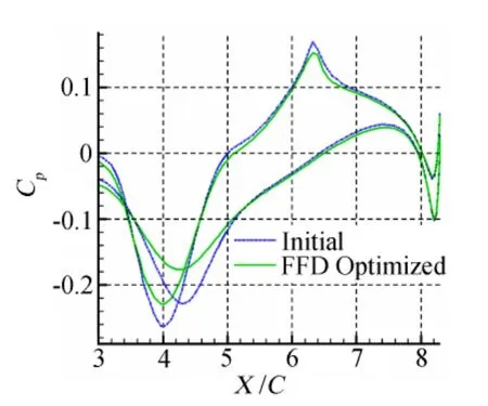
Fig.11 Pressure distribution on the symmetry plane图11 对称面压力分布
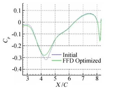
Fig.12 Z/C=0.6 pressure distribution图12 Z/C=0.6压力分布
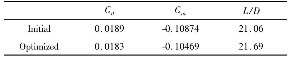
表2 优化前后气动特性Table 2 Aerodynamic characteristics after the optimization
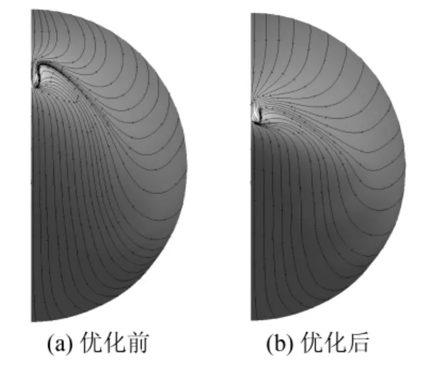
Fig.13 Limiting stream line on afterbody图13 表面极限流线对比
6 Conclusion
The presented work in this paper is the optimization design of transport afterbody by FFD parametric method integrated with Kriging surrogate model and quantum particle swarm algorithm,which are adopted to establish the aerodynamic optimization design management frame.
A numerical test is done for a typical transport afterbody considering the wing wake flow,from which the result shows that the downwash of the wing could lead to a decrease of the local angle of attack of the body flow field,so the maximum height location of the upper outline of the optimized configuration is more ahead than that without the wing interference,and the bottom outline with the wing interference becomes lower than that without the wing interference.This test shows that the afterbody flow field is affected by the wing wake flow dramatically,so the design of the afterbody should take that influence into consideration.
The body pressure dragis reduced after the optimization design by reducing the pressure recovery gradient.The drag coefficient decreases by 6 counts with comparison of that prior optimization and the lift-drag ratio increases by 3%.
The aerodynamic optimization design system for transport’s afterbody established in this study is of good optimization design efficiency and indicates a promising future of engineering application.
[1]Wortman A.Reduction of fuselage form drag by vortex flows[J].Journal of Aircraft,1999,36(3):501-506.
[2]Epatein R J,Carbonaro M C,Caudrom F.An experimental investigation of the flow field about an upswept afterbody[J].Journal of Aircraft,1994,31(6):1281-1290.
[3]Huang Y,Ghia U,Osswald G A,et al.Analysis and numerical simulation of 3-D flow past axisymmetric afterbody using Navier-Stokes equations[R].AIAA 1993-0683.
[4]Zhang Binqian,Wang Yuanyuan Duan Zhuoyi,et al.Design method for large upswept afterbody of transport aircraft[J].Acta Aeronautica et Astronautica Sinica,2010,31(10):1933-1939.(in Chinese)张彬乾,王元元,段卓毅,等.大上翘机身后体设计方法[J].航空学报,2010,31(10):1933-1939.
[5]Kong Fanmei,Hua Jun.Effects of geometry parameters and flow parameters on drag coefficient of upswept afterbodies[J].Journal of Beijing University of Aeronautics and Astronautics,2003,29(1):39-42.
[6]Kolesar C E,May F.An after drag prediction technique for military airlifters[R].AIAA 1983-1787.
[7]Thomas J Otahal,et al.An investigation of two dimensional CAD generated models with body decoupled cartesian grids for DSMC[C]//34thAIAA Thermophysics Conference,2000:19-22.
[8]Zhu Xinxiong.The technical of free curve and surface sculpt[M].Beijing:Science Press,2000.(in Chinese)朱雄心.自由曲线曲面造型技术[M].北京:科学出版社,2000.
[9]Sederberg T W,Parry SR.Freeform deformation of solid geometric models[J].Computer Graphics,19886,22(4):151-160.
[10]Smith R E.Transfinite interpolation(TFI)generation systems[M].eds.N.P.Weatherill,J.F.Thompson,B.K.Soni.Handbook of Grid Generation,CRC Press,1999.
[11]Menter F R.Two-equation eddy-viscosity turbulence models for engineering applications[J].AIAA Journal,1994,32(8):269-289.
[12]Chen Peng,Li Jian,Guan Tao.The optimization of parameters of kriging correlation model based on particle swarm optimization[J].Microelectronics& Computer,2009,26(4):178-181.(in Chinese)陈鹏,李剑,管涛.基于PSO的Kriging相关模型参数优化[J].微电子学与计算机,2009,26(4):178-181.
[13]Shinkyu Jeong,Mitsuhiro Murayama,Kazuomi Yamamoto.Efficient optimization design method using Kriging model[J].Journal of AIAA,2005,42(2):413-420.
[14]Sun J,Feng B,Xu W B.Particle swarm optimization with particles having quantum behavior[C]//Proc of the IEEE Congress on Evolutionary Computation,2004:325-331.
[15]Knill D L,Giunta A A.Response surface models combining linear and euler aerodynamics for supersonic transport design[J].Journal of Aircraft,1999,36(1):75-86.