Dynamic study on ultrasonic horn
2015-11-03XinghongZHANGXinCHENTaoHELeiQIU
Xing-hong ZHANG, Xin CHEN, Tao HE, Lei QIU
(Chongqing Key Laboratory of Time-grating Sensing and Advanced Testing Technology,Chongqing University of Technology, Chongqing 400054, China)
Dynamic study on ultrasonic horn
Xing-hong ZHANG, Xin CHEN*, Tao HE, Lei QIU
(Chongqing Key Laboratory of Time-grating Sensing and Advanced Testing Technology,Chongqing University of Technology, Chongqing 400054, China)
As an important part of power ultrasonic vibration system, ultrasonic horn can amplify the displacement of mechanical vibration and concentrate energy on a smaller radiating surface, and the amplification coefficient of ultrasonic horn is a vital parameter in vibration system. The longitudinal vibration wave equation of conical ultrasonic horn is established according to differential element method and solved by the method of separation of variables and boundary conditions, to attain the mathematical expression between amplification coefficient and three variables called the ratio of the small end to the large end diameter, length and external excitation frequency. Two of the three variables are set successively as constants, and then amplification coefficient can be achieved according to the third variable sampling value by the mathematical expression. The sample calculating data of ultrasonic horn is applied to get fitting curve by Matlab, and relationships between amplification coefficient and three variables are analyzed, qualitatively.
Ultrasonic horn, Differential element method, Amplification coefficient, Curve fitting
1 Introduction
When machining with intractable materials with ultrasonic assisted turning, periodical separation of cutting tool and processing materials, lead to the decrease of cutting force, lower cutting temperature and thinner chip formation. Compared with the traditional turning processing, ultrasonic assisted turning can not only make surface roughness and roundness of parts improved significantly, but can extend the life of cut tool by hundreds or thousands times, and processing cost greatly reduces[1-3]. The ultrasonic assisted turning technology has become one of important processing methods of complex parts, such as high hardness materials, synthetic materials, ceramics, high strength glass and other hard processing material. Horn is an important component of ultrasonic assisted processing system, it can amplify the displacement of mechanical vibration and concentrate energy on a smaller radiating surface, and effectively delivers the sound energy to load by impedance matching between transducer and acoustic load [4-8].
Longitudinal vibration wave equation of conical ultrasonic horn is established according to differential element method and solved by the method of separation of variables and boundary conditions, to attain the mathematical expression between amplification coefficient and three variables called the ratio of the small end to the large end diameter, length and external excitation frequency. Two of the three variables are set successively as constants for better research, and then amplification coefficient is achieved according to the third variable sampling value. The sample calculating data of ultrasonic horn is applied to get fitting curve by Matlab, and relationships between amplification coefficient of horn and three variables, are qualitatively analyzed.
2 Wave equation of ultrasonic horn
2.1 Longitudinal vibration of continuous elastomer
Vibrating particle can cause vibration of adjacent particles in elastic medium. Assuming that the elastic medium is divided into several layers, each layer is composed of many particles closely linked to each other. Once one particle of the medium disturbed, the movement would deviate from its equilibrium position, it will inevitably drive the neighboring particle begin to move, due to the contact exists between particles. In this way, the vibration of object is spread through elastic medium. It’s called fluctuation [6]. In order to be convenient for research, assuming that variable cross-section rod is composed of homogeneous and isotropic materials, omitting mechanical losses. When the size of cross section is far less than wavelength, it can be affirmed that stress distribution on cross section of rod is uniform when plane wave spreads along the screw axial [7].
2.2 Establishment of wave equation
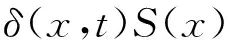
Differential element method is a way of thinking from local to overall, and we can use known physical laws to solve some complicated physical process quickly by this method. As shown in Fig.1, a rectangular coordinate system is established in the origin of coordinates on the left side of horn.δ(x, t) is given for displacement with position x and time t, the dynamic equation can be established by Newton’s second law as:
(1)
Where,σ(x) is the force with position x on the cross section and time t,σ(x+Δx) is the force with positionx+Δxon the cross section and time t, ρ is the material density of horn,S(x) is the cross-sectional area.
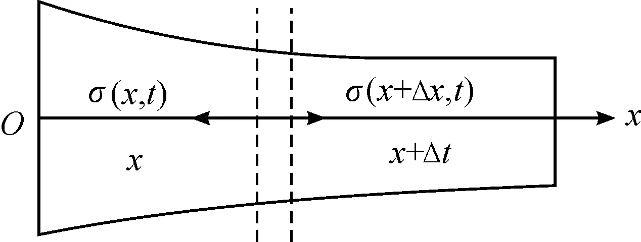
Fig.1 Longitudinal vibration of variable cross-section rod
So, when Δxis approaching 0:
(2)
Of which the force is:
(3)
The equation of harmonic vibration [10] is:
(4)
Take longitudinal vibration equation, and then get wave equation of variable cross-section horn:
(5)
(6)
(7)
Where, k is the wave number, ω is the frequency, c is the longitudinal wave propagation velocity in horn.
3 Solution of wave equation
The method of separating variables is aimed to divide original equation into several simpler differential equations that containing only one independent variable by separating each variable apart. According to the principle of linear superposition, split inhomogeneous equations into multiple homogeneous or easy-solving equations. Using mathematic methods to achieve the general solution of equations, and assembled all the general solution “together” finally.
3.1 Longitudinal vibration of continuous elastomer
There exists two situations in boundary of continuous longitudinal vibrating rod piece, one is that end face is force free, force on the face is zero according to Newton’s third law; another is that end face is under force. The equation established in both cases are based on Hooker’s law, as shown in Fig.2, force and displacement of two end faces are given as F1, F2andδ1,δ2,respectively.
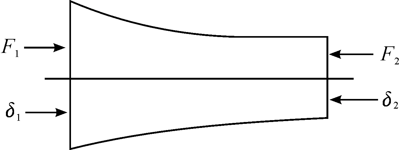
Fig.2Diagramofstress
i)Whenendfaceisforcefree,theaxialforceiszero,takesforHooker’slaw:
(8)
(9)
ii) When end face is under force, takes for Hooker’s law:
(10)
(11)
3.2 Solution of amplification coefficient
According to the characteristic of harmonic vibration equation, solution of wave equation can be expressed as:

(12)
Using wave equation (5) to achieve:
(13)
The given parameter of diameter of conical horn, with position x= 0, x= l, are D1 and D2, respectively. So the functions of cross sectional area and diameter are:
(14)
(15)
Of which, S1is the cross sectional area of horn, and parametersα, N are given as:
(16)
(17)
Here is the final wave equation:
(18)
So, displacement function is:
(19)
As shown in Fig.2, the force on the end of horn is F1and F2, respectively. When the end of horn is force free, the force is zero no matter what value t is. According to the boundary conditions and Hooker’s law mentioned before, constants can be determined:
(20)
And then the amplification coefficient can be expressed as:
(21)
4 Analysis and curve fitting of amplification coefficient
When designing, material of the horn should be chosen after determining the maximum displacement. The material of horn is 1045, which is selected based on the require of application. The physical parameters of 1045 are shown in Table 1.
Table 1 Physical parameters of 1045
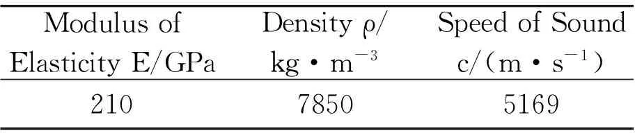
ModulusofElasticityE/GPaDensityρ/kg·m-3SpeedofSoundc/(m·s-1)21078505169
Then choose an initial value for the operating frequency, in order to produce high amplitude and to minimize the effect of heat generation on performance of transducer. The initial value is chosen as 20 kHz which represents, theoretically, the low ultrasonic threshold [9].
Considering the relationships of amplification coefficientMpand diameter ratioN, the length l and external excitation frequencyf, set successively two of the three variables as constants, and then achieved the relationship based on sampling calculations of the third variable and amplification coefficient.
Setlandfto fixed values. The frequency here was 20 kHz, and the length of half wave ultrasonic horn was 0.129 m. Sampled value ofNverified from 1.0 to 7.9.
Then, the vibration frequency f=20 kHz and N=3.8 were assumed. Sampled length of horn verified from 0.114 m to 0.160 m, and sampling interval was 0.002 m.
Assumed both l and N as constant values, l=0.129 m, N=3.8. Sampled frequency verified from 6 kHz to 29 kHz, and sampling interval was 1×10³kHz.
Got curve fittings through Matlab. Approximate straight line was shown in Fig.3. And known from Fig.4, the amplification coefficient decreased with growth of length. According to the Fig.5, maximum of amplification coefficient corresponded to frequency of f0(natural frequency of the ultrasonic horn).
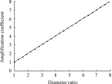
Fig.3 Relationship between amplification coefficient and diameter ratio
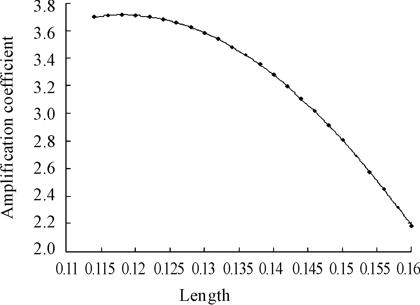
Fig.4 Relationship between amplification coefficient and length
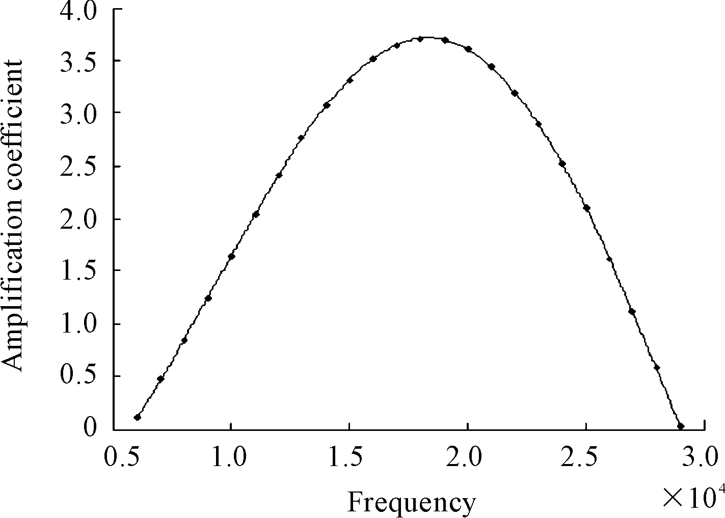
Fig.5 Relationship between amplification coefficient and external excitation frequency
5 Conclusions
Relationships of above variables can be concludes as:
1) When length of horn and external excitation frequency are constant values, it can be seen from the fitting curve that amplification coefficient shares approximate linear relationship with the ratio of the small end to the large end diameter.
2) When the ratio of the small end to the large end diameter and external excitation frequency are constant values, it can be seen from the fitting curve that amplification coefficient decreases with the increase of length of horn, especially when the length of horn is greater than half wave length, amplification coefficient decreases faster with the increase of length.
3) When length of horn and diameter ratio of end face are constant values, and vibration frequency as a certain value of f0, the amplification coefficient is the largest. When external excitation frequency is lower than f0, amplification coefficient increases as the frequency increases. When external excitation frequency is higher than f0, amplification coefficient decreases as the frequency increases.
[1]WANG Hongfei, Research of vibration assisted turning cutting technology and its development [J]. Machinery Design Manufacture, 2007(10): 212-215.
[2]Brehl D E, Dow T A. Review of Vibration-assisted Machining [J]. Sciencedirect Precision engineering, 2008 (32): 153-172.
[3]PAN Hui. Design of Ultrasonic Horn and Its Performance Analysis [J]. Equipment Manufacturing Technology, 2009 (8): 69-72.
[4]ZHAO Li, WANG ShiYing. Dynamic Analysis of the Horn in Ultrasonic Machining [J]. Electromachining & Mould, 2005 (2): 34-38.
[5]HE XiPing, GAO Jie. A review of ultrasonic solid horn design [J]. Technical Acoustics, 2006, 25(1): 82-87.
[6]CHU Tao. Finite element analyses of the ultrasonic amplitude transformer [J]. Mechanical & Electrical Engineering Magazine, 2009, 26(1): 102-106.
[7]ZHU Yin. Resonant analysis of ultrasonic amplitude horn with Finite Element Method [J]. Design and Research, 2005, 32(12): 13-15.
[8]FU Jin. The Design and Production of Transformers in the Process of Micro-ultrasonic Machining[J]. Modern Machinery, 2010 (2): 33-38.
[9]Sergei L P, Alexey S P. Matching a transducer to water at cavitation: Acoustic horn design principles [J]. Industrial Sonomechanics, 2007: 314-322.
[10]SHE Yinzhu, LU Ming, WANG Shiying. Numerical Design of 1/2 Wavelength Composite Solid Horn [J]. Journal of TaiYuan University of Technology, 2011, 42(6): 630-633.
Introduction of the Fluid Control Engineering Institute of Kunming University of Science and Technology
The Fluid Control Engineering Institute of Kunming University of Science and Technology was set up in 1996. The researches of institute concentrate on electro-hydraulic(pneumatic) servo/proportional control and hydromechatronics. The Institute is committed to research and development of electro-hydraulic control of high-end technical equipment in ferrous metallurgy refining production. Projects undertaken and participated by the copper electrolysis anode preparation equipment, lead residual anode washing production lines as a host device received the second prize of the National Science and Technology Progress Award in 2009, the first prize and the third prize of the Yunnan Provincial Science and Technology Progress Award and many other awards. The institute has developed and put into operation more than a dozen sets of large equipment, and more than 20 national patents, which have been transformed into related products, providing professional package services of technology and equipment for non-ferrous metallurgical enterprisesAddress:College of Mechanical and Electrical Engineering, Chenggong Campus of Kunming University, 727#,Jingming South Road, Chenggong University City, Kunming City, Yunnan Province
Zip Code:650500
Contact:Sun Chungeng, 13608850651/Liu Sen, 13888749366
超声变幅杆的动力学分析
张兴红,陈鑫*,何涛,邱磊
重庆理工大学 时栅传感及先进检测技术重庆市重点实验室,重庆400054
超声变幅杆是功率超声振动系统的重要组成部分,它的主要功能是把机械振动位移放大并把能量集中在较小的辐射面上,变幅杆的放大系数是超声振动系统中的重要参数。用微元法建立圆锥形超声变幅杆纵向振动的波动方程,用分离变量法和连续振动体的边界条件求解超越波动方程,得到圆锥形超声变幅杆放大系数与变幅杆的大小端直径之比、长度以及外激频率3个变量之间的数学表达式。为研究变幅杆的放大系数与变幅杆的大小端直径之比、长度以及外激频率的关系,依次把3个变量中的2个变量设为常量,对另外一个变量进行抽样,计算变幅杆的放大系数。通过Matlab对超声变幅杆放大系数的样本计算数据进行曲线拟合,定性分析了圆锥形超声变幅杆放大系数随变幅杆大小端直径之比、长度、外激振动频率变化的关系。
超声变幅杆;微元法;放大系数;曲线拟合
Fig.1 The copper electrolysis anode preparation equipment
2 September 2014; revised 15 December 2014;
Xin CHEN, E-mail: hetao814185754@2012.cqut.edu.cn
10.3969/j.issn.1001-3881.2015.18.013 Document code: A
TB532
accepted 12 March 2015
Hydromechatronics Engineering
http://jdy.qks.cqut.edu.cn
E-mail: jdygcyw@126.com
猜你喜欢
杂志排行
机床与液压的其它文章
- Manufacturing of self-lubricating diamond tools with Ni-Cr alloy adding with Ni/C
- Vibration response analysis of a lathe spindle by using the ANSYS finite element method
- Car following model with consideration of the vehicle’s mechanical inertia effect and its stability analysis
- Software design for spur gear tooth thickness based on MATLAB/GUI
- Analysis and research of OPC technology in coal mine monitoring data transmission system
- Based on Cortex-M4 torus worm tester full closed loop control system