Polarization-Dependent Optimization of Fiber-Coupled Terahertz Time-Domain Spectroscopy System
2015-07-14JingYangShanHeJiaYuZhaoLanJunGuoandWeiWeiLiu
Jing Yang, Shan He, Jia-Yu Zhao, Lan-Jun Guo, and Wei-Wei Liu
1. Introduction
In the rapidly developing field of terahertz science and technology, the terahertz time domain spectroscopy(THz-TDS) system is by far one of the most important methods to retrieve the spectroscopic and temporal characteristics of THz wave[1]. And a large portion of THz-TDS system uses photoconductive antennas (PCAs) to generate and detect broadband terahertz pulses in view of their merits of compactness, high efficiency, and maneuverability[2]. In practice, the femtosecond lasers,which are centered at 800 nm, 1 μm, and 1.55 μm, are most frequently implemented to pump the PCAs. Particularly,THz-TDS system operated at 1.55 μm laser wavelength is of great interest because of the feasibility to use the optical fiber to deliver the laser beam. It could not only significantly improve the robustness of TDS system, but also make TDS system benefit from a variety of fiber components developed and matured originally for fiber-telecom applications. The successful development of a low temperature grown InGaAs/InAlAs multilayer structures has broken the long existing bottleneck of PCA operating at 1.55 μm laser wavelength[3], leading to the commercialization of the fiber-coupled THz-TDS system.
During the operation, interest has been mainly focused on the dispersion compensation of the fiber in order to optimize the property of a fiber-coupled THz-TDS system[4].However, little attention has been paid to the polarization effect on the performance of a fiber-coupled THz-TDS system operating at 1.55 μm. In this paper, we report polarization dependent performance of the fiber-coupled THz-TDS system. The effects of polarization on the emission power and the temporal features of the THz waveform were investigated. The results indicate that the best performance of TDS system could be achieved when the laser polarization is perpendicular to the electrodes of the conductive antennas. Under this condition, the emission power is the maximum and the pulse width is the minimum.However, the generated THz wave power and pulse width will degrade with respected to the rotation of the laser polarization. The observation has been mainly attributed to the birefringence of the optical fiber.
2. Experiment Setup
The experimental setup of the fiber-coupled THz-TDS system used in our work is shown in Fig. 1. A femtosecond pulsed fiber laser (CALMAR Systems) is used. The laser emits at 1550 nm, delivering 80 fs pulses at a repetition rate of 100 MHz. The averaged output power of the laser is about 600 mW. By using a beam splitter, only a small fraction of the laser power (~30%) is sent to the TDS system in order to avoid the damage of the fiber and the PCAs. The laser beam is then focused from the free space into a 1×2 fiber coupler by a lens (L1). The coupling efficiency is about 60%. The fiber coupler is made of dispersion compensation fiber (Thorlabs). One output of the coupler is used as the pumping source of a fiber coupled PCA (emitter, Fraunhofer IPM) to generate THz pulses. The other output of the coupler has been adhered a GRIN fiber collimator (L2). The collimated beam is then coupled back to another fiber by an identical GRIN fiber collimator (L3).Between L2 and L3, a time delay line is constructed as indicated in Fig. 1. After that, the second beam delivered by the fiber is shot on another fiber coupled PCA (receiver) for the detection of the THz pulses. It is worth mentioning that the dispersion has been carefully taken care of by fabricating the fiber coupler with properly length determined in a preparation experiment. In both the emitter and receiver, hyper-hemispherical silicon lenses are attached to the backside of the PCAs to reduce the divergence of the THz pulses. When performing TDS measurement, a bias voltage (10 V), which is given by a function generator and sinusoidally modulated at 1 kHz, is applied to the emitter. The THz pulses generated by the emitter is first collimated by an off-axis parabolic mirror(1 inch diameter and f=2 inch, P1) and focused by another identical parabolic mirror (P2) into the receiver. The photocurrent signal of receiver is finally detected by using a lock-in amplifier synchronized to the bias modulation of the emitter.the laser is illuminated on the emitter PCA. As illustrated by Fig. 1, the THz pulse power is measured by focusing the THz pulses by the third parabolic mirror (P3) into a calibrated Golay cell (TYDEX). Reference [5] has indicated that foam is an excellent material for using a filter to block near-IR light while transmitting THz wave, so a 3 cm thick foam plate is put in front of the Golay cell to block the leaked laser light from the emitter. The obtained results are shown in Fig. 2. Note that the laser polarization is measured with respect to the edge of the two parallel electrodes of the emitter PCA in this paper, i.e., 90°means the laser polarization is perpendicular to the edge of the two parallel electrodes of the PCA. Fig. 2 demonstrates that the maximum THz power is achieved when the laser polarization is perpendicular to the PCA electrodes, while in the case of parallel configuration, the generated THz power is the lowest, being approximately 80% of the peak value.
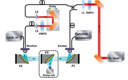
Fig. 1. Schematic of experimental setup for generation and detection of THz pulses.
Our results shown in Fig. 2 agree with the main conclusion revealed by previous reports that THz pulse power emitted by a PCA emitter can be optimized when the excitation laser polarization is perpendicular to the electrode edges[6]. The enhancement of the excitation intensity by the anode edge effect could account for the observation[7]. It is also worth mentioning that the power of the leaked laser light from the emitter has also been measured during our experiment. The laser power decreases less than 6% when the laser polarization changes from 90°to 0°. That further confirms that the polarization dependent absorption of the laser power does not play dominant role in the experiment[6].
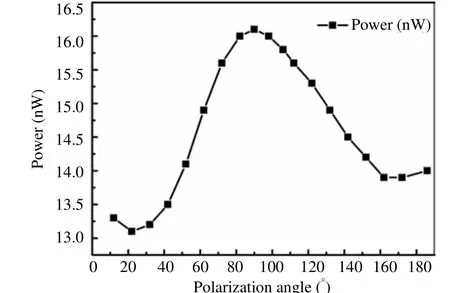
Fig. 2. THz output power measured by Golay cell as a function of laser polarization.
3. Results and Analysis
In order to investigate the polarization effect on the fiber coupled THz-TDS system, as indicated by Fig. 1, two zero-order half-wave plates are inserted before the focusing lens (HWP1) and between two GRIN fiber collimators(HWP2), respectively. The generated THz power is first studied as a function of the laser polarization by rotating HWP1. The pump laser polarization is determined by putting a polarizer after the parabolic mirror and measuring the polarization of the leaked laser from the emitter when
On the next step, the polarization of the pumping source is fixed at 90°, that is, THz output power of the emitter is approximate to the maximum. Then, the THz pulse waveform retrieved by the receiver is studied by adjusting the polarization of the probing source via rotating the HWP2. Fig. 3 gives three representative THz waveforms at probe laser polarization of 0°, 40°, and 90°,respectively. It is interesting to see that both the amplitude and the shape of the THz pulse waveform vary with the laser polarization. When the laser polarization of the receiver is 90°, i.e., perpendicular to the electrodes, the obtained THz pulse waveform is nearly single-cycled.However, the secondary pulse following the main pulse can be observed in the other two THz waveforms, and the amplitude of the secondary pulse will be increased when the polarization direction of probe laser varying from 90°to 0°. Besides, Fig. 4 outlines the evolution of the peak-peak amplitude of the main pulse of THz pulse waveforms with respect to the probe laser polarization. Similar to Fig. 3, the maximum amplitude is observed at 90°polarization, and the minimum is found at 0°. The ratio between the minimum and the maximum is about 0.6.
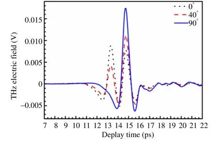
Fig. 3. THz electric field waveforms retrieved by TDS when laser polarization is at 0°, 40°, and 90°, respectively.
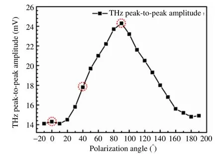
Fig. 4. THz waveform peak-to-peak amplitude as a function of polarization of pump laser.
The waveform distortion shown in Fig. 3 is surprising.It could not be simply explained by the laser polarization dependent excitation intensity of the photoconductive antenna by the anode edge effect[7]. Since the waveform distortion will directly affect the spectroscopic performance of the TDS system, it will be a crucial concern for the THz-TDS system optimization. It is well known that the temporal dynamics of the PCA based receiver are mainly determined by the laser pulse shape and the intrinsic free-carrier life time of the PCA[4]. The later remain unaltered during our experiment, therefore the change of the laser pulse temporal shape could be the main reason causing the evolution of the THz pulse waveform shown in Fig. 3. In order to confirm it, the laser pulse has been characterized by an interferometric autocorrelator before it shots on the receiver antenna. Fig. 5 shows three representative autocorrelation traces at different laser polarization angles, namely, 0°, 40°, and 90°. Pulse splitting can be clearly noticed in Fig. 5. The interval between two pulses is about 1.2 ps. It is consistent with the temporal delay of the two THz waveform peaks shown in Fig. 3. Fig.5 also indicates that when the laser polarization is mainly perpendicular to the antenna electrodes, the satellite pulse has minimum intensity and the main laser energy is constrained in the main pulse. Hence, in this case the generated retrieved THz signal is single cycle and has maximum amplitude. On the other hand, when the laser polarization deviated from the perpendicular direction, due to the birefringence of the optical fiber, the laser pulse would be separated into two orthogonally polarized pulses.Consequently, the free-carrier of PCA will be excited twice with a temporal delay given by the birefringence of the fiber. It finally results in the retrieved THz waveforms shown in Fig. 3. In our experiment, if taking into account that the polarization maintaining (PM) fiber length is 1 m,1.2 ps delay time corresponds to a birefringence of ∆n≈2.5 ×10⁻⁴, which is in good agreement with the reported values[8].
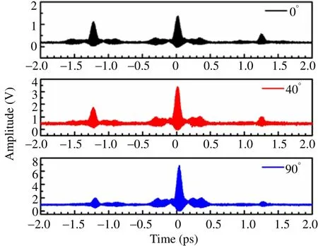
Fig. 5. Interferometric autocorrelation trances of pump laser pulse with HWP2 rotation angles of 0°, 40°, and 90°, respectively.
4. Conclusions
In conclusion, the output performance of a fiber-coupled THz-TDS system has been studied as a function of the pump laser polarization. Two photoconductive antennas based on InGaAs/InAlAs multilayer structures have been used as the emitter and receiver, respectively. It was found that the THz output power of the emitter arrived at the maximum with the polarization direction of pump laser pulse perpendicular to the edge of electrodes. At the same time, the THz waveform detected by the receiver is close to the single-cycled pulse when the polarization direction of probe laser pulse is also perpendicular to the edge of electrodes. Otherwise, double THz pulses may be induced, leading to interference of the THz spectrum. Pulse splitting associated with the optical fiber birefringence has been proposed to explain the observed phenomena. Therefore, besides the dispersion compensation, polarization optimization should be another crucial factor needing to be taken into account when a fiber-coupled THz-TDS system is applied.
Acknowledgment
Authors acknowledge the support of the open research funds of State Key Laboratory of High Field Laser Physics, Shanghai Institute of Optics and Fine Mechanics (SIOM).
[1] P. U. Jepsen, D. G. Cooke, and M. Koch, “Terahertz spectroscopy and imaging—Modern techniques and applications,” Laser & Photonics Reviews, vol. 5, no. 1, pp.124–166, 2011.
[2] B. Heshmat. H. Pahlevaninezhad, and T. E. Darcie, “Optical efficiency enhancement methods for terahertz receiving photoconductive switches,” Optics & Laser Technology, vol.54, pp. 297–302, Dec. 2013.
[3] H. Roehle, R. J. B. Dietz, H. J. Hensel, et al., “Next generation 1.5 µm terahertz antennas: mesa-structuring of InGaAs/InAlAs photoconductive layers,” Optics Express,vol. 18, no. 3, pp. 2296–2301, 2010.
[4] B. Sartorius, H. Roehle, H. Kunzel, et al., “All-fiber terahertz time-domain spectrometer operating at 1.5 μm telecom wavelengths,” OSA Optics Express, vol. 16, no. 13,pp. 9565–9570, 2008.
[5] G. Zhao, M. ter Mors, Tom Wenckebach, and Paul C. M.Planken, “Terahertz dielectric properties of polystyrene foam,” J. Opt. Am. B, vol. 19, no. 6, pp. 1476–1479, 2002.
[6] P. G. Huggard, C. J. Shaw, J. A. Cluff, and S. R. Andrews,“Polarization-dependent efficiency of photo-conducting THz emitters and receivers,” Applied Physics Letters, vol. 72, no.17, pp. 2069–2071, 1998.
[7] S. E. Ralph and D. Grischkowsky, “Trap-enhanced electric fields in semi-insulators: The role of electrical and optical carrier injection,” Applied Physics Letters, vol. 59, no. 16,pp. 1972–1974, 1991.
[8] N. Juichi, O. Katsunari, and S. Yutaka,“Polarization-maintaining fibers and their applications,”Journal of Lightwave Technology, vol. LT-4, no. 8, pp.1071–1088, 1986.
杂志排行

Journal of Electronic Science and Technology的其它文章
- Non-Supervised Learning for Spread Spectrum Signal Pseudo-Noise Sequence Acquisition
- Face Detection under Complex Background and Illumination
- Transformation of Voltage Mode Filter Circuit Based on Op-Amp to Circuit Based on CCII
- An Evolution, Present, and Future Changes of Cloud Computing Services
- Backlit Keyboard Inspection Using Machine Vision
- Efficient Slew-Rate Enhanced Operational Transconductance Amplifier