Design and Control of Self-Heat Recuperative Distillation Process for Separation of Close-Boiling Mixtures: n-Butanol and iso-Butanol
2015-06-22LiLuminLiuYuliangZhaiJianSunLanyiTianYuanyu
Li Lumin; Liu Yuliang; Zhai Jian; Sun Lanyi; Tian Yuanyu
(State Key Laboratory of Heavy Oil Processing, China University of Petroleum, Qingdao 266580)
Design and Control of Self-Heat Recuperative Distillation Process for Separation of Close-Boiling Mixtures: n-Butanol and iso-Butanol
Li Lumin; Liu Yuliang; Zhai Jian; Sun Lanyi; Tian Yuanyu
(State Key Laboratory of Heavy Oil Processing, China University of Petroleum, Qingdao 266580)
In order to explore the advantages of self-heat recuperative distillation (SHRD) process, the design and control of the SHRD process was studied for the separation of n-butanol and iso-butanol mixtures. The economic superiority of SHRD process is presented when a comparison on the total annual cost (TAC) of the conventional distillation process, the vapor recompression distillation process and the SHRD process was made. For the SHRD process, 37.74% and 11.35% savings of TAC can be achieved as compared to the conventional distillation process and vapor recompression distillation process, respectively. The dynamic characteristics of this promising SHRD sequence had been studied, and the dynamic responses demonstrated that 10% changes in both feed flow rate and feed composition can be well handled by the control strategy with dual-temperature control. It is proven that the SHRD system not only can provide economical savings but also can operate normally with good controllability.
n-butanol; iso-butanol; self-heat recuperative distillation; total annual cost; control
1 Introduction
Distillation is one of unit operations widely used in petrochemical processes. However, distillation is also a wellknown process which requires a great deal of energy for the phase change and separation. Moreover, the CO2emissions are strongly related to energy consumption in distillation since the energy is mostly generated through the combustion of fossil fuels. Thus the energy savings of distillation process have been continuously attracting enormous interest from all over the world both in academic and industrial circles. Heat integration in distillation systems is an effective method to save energy, such as the dividing-wall column (DWC)[1-2], the heat pump assisted distillation[3-4]and the heat-integrated distillation column (HIDiC), etc.[5-6]Among these innovative methods, the heat pump assisted distillation process and the heat-integrated distillation process often use a compressor to increase the pressure and temperature of vapor stream, which after compression can be used to heat the liquid stream. However, the traditional heat recovery methods are adopted in these distillation processes without considering the preheating section. Recently, Kansha, et al. developed a self-heat recuperation technology which focused on the use of both latent heat and sensible heat.[7]In this attractive technology, the heat of process streams can be recycled to the process without any heat addition, which can bring about significant energy savings to the process. Then this attractive self-heat recuperation technology was applied to distillation process and the innovative self-heat recuperative distillation (SHRD) was proposed by Kansha, et al.[8]Figure 1(a) shows the flowchart of a SHRD process consisting of the preheating module and the distillation module, and in each module the total enthalpy of feed streams is equal to all enthalpy items of effluent counterparts. Figure 1(b) presents the temperature and heat relationship for the SHRD process, of which Tstdand Tbare the standard temperature and boiling point of stream 1, respectively. Each number in Figure 1(b) stands for the corresponding stream number of Figure 1(a). In this innovative SHRD process the vapor stream from the column overhead will be used as the heat source of feed stream and bottoms, which leads to significant energysavings. It is reported that the energy requirement of SHRD process can be decreased to 1/6—1/8 as compared with the traditional heat-exchanged distillation process[9]. Kansha, et al.[10]applied the self-heat recuperation technology to the flash distillation process, and the innovative process can achieve more than 75% reduction in the energy requirement as compared with the traditional process. On the basis of self-heat recuperation technology, Kansha and his co-workers then studied the HIDiC process, and the results showed that the developed distillation process was effective with further reduction of energy requirement[11]. Matsuda, et al.[12-13]also demonstrated that the distillation and petrochemical processes which applied the self-heat recuperation technology could achieve significant energy savings.
In the carbonylation process for synthesizing n-butanol, the residues contain n-butanol, iso-butanol and some high boiling point components. However, the separation of these close-boiling mixtures consumes a great deal of energy. To reduce the energy requirements in the separation of n-butanol and iso-butanol mixtures, Gao, et al.[14]studied two types of mechanical vapor recompression heat pump distillation processes. The results indicated that the two processes were more economically favorable in both energy requirements and total annual cost (TAC). Nevertheless, the preheating section of feed stream has not been considered in the case of n-butanol/iso-butanol mixture separation.
Though most of the previous works reported the design of distillation process that applied the self-heat recuperation technology, the related control system design of the SHRD process has not been fully investigated previously[15]. This work can be considered as an important supplement to the previous studies, with the focus being put on the application of SHRD and control issues. In this work, the SHRD process is used to separate the mixtures of n-butanol and iso-butanol for the first time, and then the TAC of the conventional distillation process, vapor recompression distillation column (VRC) process and SHRD process is calculated systematically. In addition, the dynamic controllability of the SHRD process is examined on the feed flow rate as well as the feed composition changes. Finally, the conclusions are drawn for evaluating the SHRD process.

Figure 1 (a) Flowchart of SHRD process; (b) Temperature and heat relationship in SHRD process
2 Steady-State Designs
As an example of close-boiling mixture separation, the system of n-butanol (with a boiling point of 117.3 ℃ at 100 kPa) and iso-butanol (with a boiling point of 107.3 ℃ at 100 kPa) was studied. Gao, et al.[14]investigated this system without considering the preheating section. However, the preheating of feed is significant as the desired feed temperature is 114.2 ℃ for the separation. In this section, the conventional distillation process, VRC process and SHRD process will be explored for the separation of n-butanol and iso-butanol mixture. Figure 2 gives the conceptual design flowsheet of the three processes, and in each process the feed should be heated and the two products should be cooled. The design of these processes were implemented using the commercial simulator Aspen Plus, and the Wilson model was applied in this binary system[14].
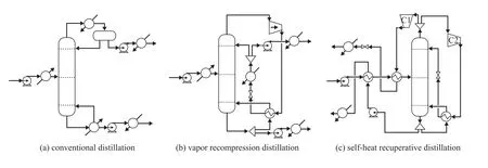
Figure 2 Design flowsheets of: (a) conventional distillation; (b) vapor recompression distillation; (c) self-heat recuperative distillation
2.1 Simulations for the proposed three processes
Figure 3 gives the steady-state flowsheet of the original one-column distillation. As shown in Figure 3, the feed flow rate is 5 000 kg/hr with the mixture composed of 55/45 n-butanol/iso-butanol, and the feed is heated before it is fed into the column. To obtain the minimum TAC, Gao, et al. investigated a range of operating pressures in their work and gave an optimal one of 90 kPa for the VRC process[14], and the operating pressure of 90 kPa was also assumed in this case. The specifications for the purity of two products (n-butanol and iso-butanol) were all set at 99.0%. To obtain a direct comparison, the feed and product conditions of VRC process and SHRD process should be consistent with those of the conventional process.
Figure 4 shows the steady-state flowsheet of VRC process in detail. In the VRC process, the overhead stream of the column is compressed by a compressor to increase the temperature and pressure. Then the compressed stream is used as the heat source of the reboiler and is simultaneously condensed. As shown in Figure 4, the condensed stream is subsequently cooled by a trim condenser. Finally the overhead stream is divided into the distillate and reflux of the column.
Figure 2(c) shows the flowsheet of the advanced SHRD process, in which the vapor distillate of the column is split into two parts. Subsequently, the divided streams are compressed by the compressors C1 and C2, respectively. The overhead product stream (compressed by C1) is cooled through exchanging heat with the feed stream. The latent heat of the other stream (compressed by C2)is treated as the reboiler duty, and then the condensed stream is recycled as the reflux to the column. The bottom stream of the column is divided, and the product stream (pure n-butanol) is used to preheat the feed stream, and the other stream functioning as the boilup is vaporized by the heat of compressed stream.
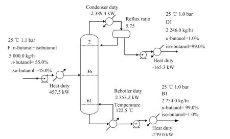
Figure 3 Process flowsheet of conventional distillation system with details
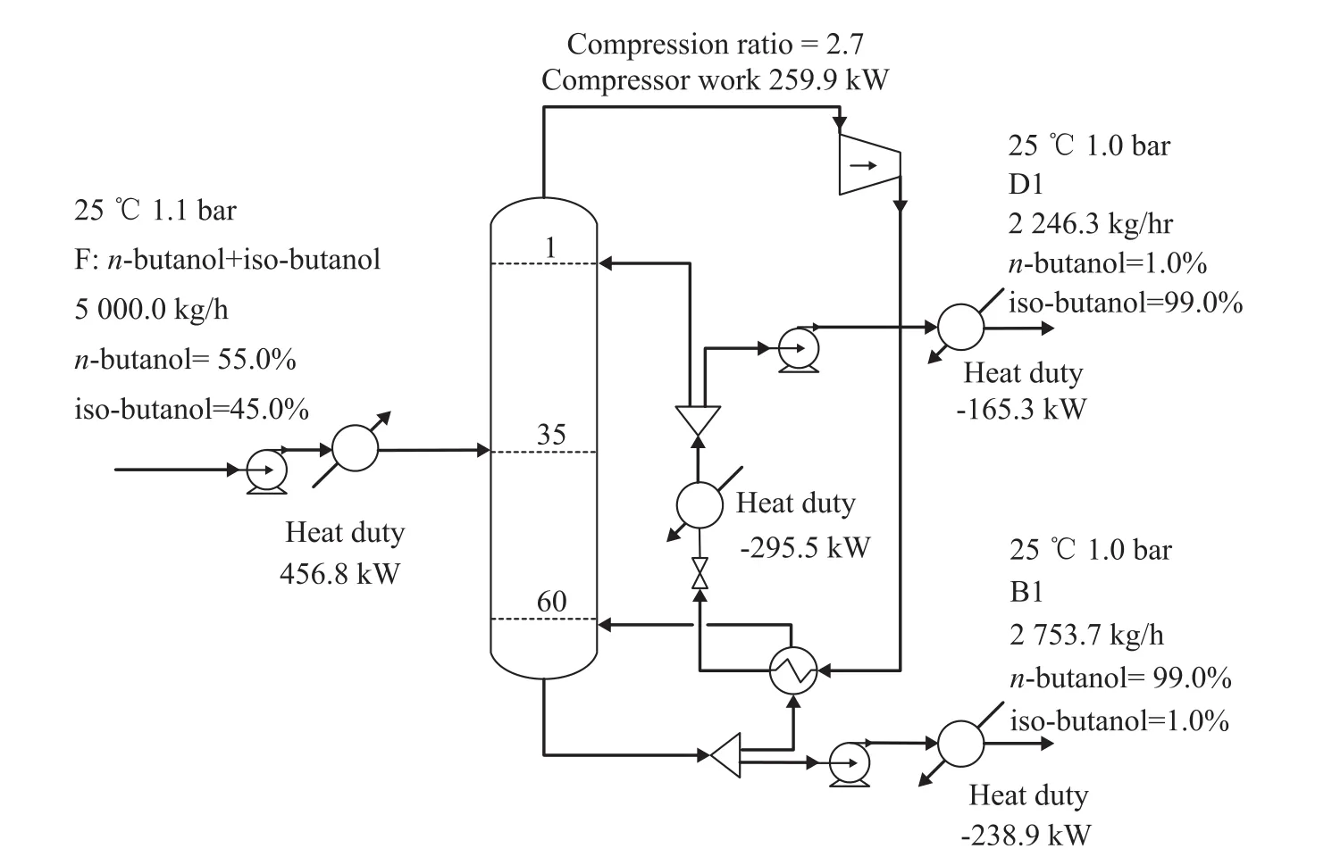
Figure 4 Process flowsheet of vapor recompression distillation system with details
2.2 Economical optimization
In this section, economical optimization is carried out to evaluate properly the economic feasibility of SHRD. TAC is used as the objective function, which can be described as Eq. (1),

where the operating cost contains the steam cost for heater and reboiler, the cost of cooling water and the electricity cost for the compressor. The capital investment includes the cost of column trays, column shell, heat exchangers and compressors excluding the small equipment like pumps and valves because of their low costs. 3 years of capital payback period and 8 000 hours/year of available operating time in a plant are assumed. 0.852 kW/(K·m2) and 0.568 kW/(K·m2) are used as the heat transfer coefficients of condensers and reboilers, respectively[16]. The capital cost estimates were suggested by Douglas[17]with updated M&S index of 1 536.5 (Chemical Engineering Plant Cost Index, 4 th Q, 2011).
The minimum TAC exists when a series of total number of trays (NT) varies under a certain feed location. To achieve the optimum parameters, the TAC of the SHRD process was calculated, and Figure 5 presents graphically the TAC of the SHRD process via changing the number of stages. It can be seen from Figure 5(a) that when the number of stages increases, the operating cost changes slightly,while the capital cost decreases firstly when NT is less than 67, and then it increases when NT is equal to or greater than 67. The minimum TAC of 682.17×10³$/year occurs when NT is 67 as revealed in Figure 5(b).
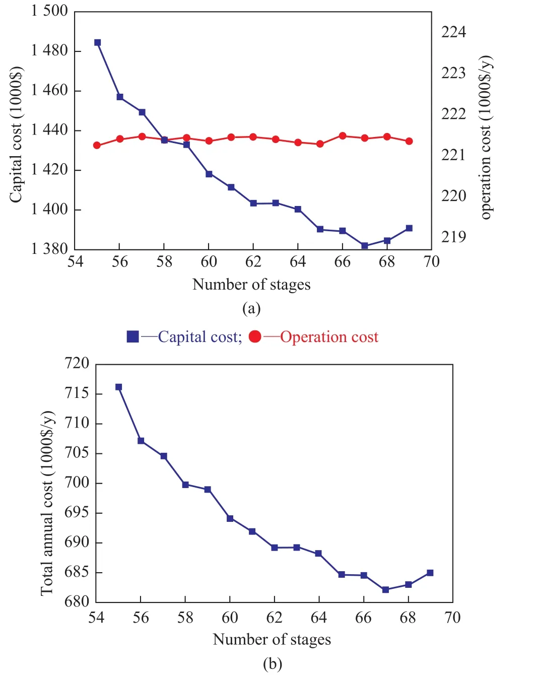
Figure 5 Effects of the number of stages on (a) capital cost and operating cost; (b) TAC of the SHRD process
To compare the three processes fairly, the conventional process and VRC process are also optimized in the same way as described in SHRD process, and the detailed simulation results are given in Table 1. As shown in Table 1, the VRC process provides a 29.77% reduction in TAC as compared with the conventional process. Moreover, the SHRD configuration can achieve 11.35% of TAC savings, as compared to the VRC design. Hence the SHRD design is the most economical one when it is compared with the conventional design and VRC design.
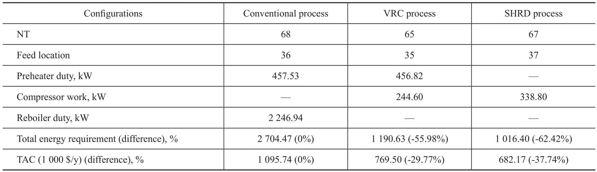
Table 1 Optimum results of the SHRD design, the conventional distillation and VRC distillation designs
3 Control Structure Design
Because the SHRD process has a greater advantage in TAC than the other two designs, it would also be interesting to examine the dynamic characteristics and controllability of this advanced process. Some dynamic parameters of the SHRD process should be specified before the simulation is exported to Aspen dynamics as the pressuredriven simulation. The diameter of SHRD column is calculated through the tray sizing function in Aspen Plus. The size of column base is specified based on a 5-min liquid holdup time with a half full level.
The overhead vapor flow rate is manipulated to control the pressure at the top of column, and the bottoms flow rate is used to control the base level of the column. After the pressure and base level are controlled, some disturbances, which include the throughput changes and feed composition changes, are introduced to investigate the stability of the proposed SHRD design. Figure 6 displays the responses of product purity under 10% feed changes. As shown in Figure 6, the feed disturbance in each case would always result in the purity reduction of one product. As the stage temperature is not controlled to meet the separation requirement, when feed flow rate increases, there is not enough energy to heat the feed stream, which will make more iso-butanol get into the distillation column bottom. On the contrary, the distillate will contain more n-butanol when the throughput decreases. In the case of feed composition disturbances, the changes on iso-butanol will have a direct impact on the product purity. For example, a +10% iso-butanol feed composition disturbance will lead to an increase in iso-butanol product purity and accordingly a decrease in n-butanol product purity.
As shown in Figure 6, though the SHRD system can achieve stable operation after various feed disturbances are introduced, the products cannot keep at their desired purity level. Therefore the control of the SHRD design will be studied afterwards. The temperature profile along the optimum SHRD column is presented in Figure 7, and the relative large slopes can be observed on the stages 20 and 50. Thus, according to the slope criterion the stages 22 and 50 will be considered as the temperature control points later. Besides the control over column pressure and base level, the feed flowrate must be controlled, and the flow rate of iso-butanol product is used to control the feed temperature. In addition, the reflux rate is manipulated to control the temperature of the stage 22 via adjusting the brake power of the compressor C2. The temperature controllers with a 1-min deadtime are tuned based on relay-feedback tests by the Tyreus-Luyben tuning rule[18]. These proposed controllers used in the loops are conventional PI controllers, and the basic control structure is presented in Figure 8.
Figure 9 shows the dynamic responses to ±10 % changesin feed stream for this basic control strategy. It is shown that despite some basic controllers used in the common cases, the two products cannot maintain the desired purity after the feed disturbances are introduced, which shows the similar trends as presented in Figure 6. Symmetrical responses with relatively large deviations can be observed in all temperature responses of the stage 22. However, the temperature responses of the stage 50 have not fluctuated similarly as the tendency of the stage 22 (see Figure 9). When the feed flow rate ranges from 5 000 kg/hr to 5 500 kg/hr, the tray temperature especially on the stage 50 shows a large decrease, leading to a great reduction in n-butanol product purity. The effect on the stage 50 is quite small when the feed flowrate is reduced by 10%, resulting in a small offset of n-butanol product purity. For an increase of 10% isobutanol in the feed composition, the tray temperature ofthe stage 50 decreases significantly with large deviations, which will affect the purity of n-butanol product.

Figure 6 Dynamic responses when the disturbances are: (a) +10% in feed flow rate; (b) -10% in feed flow rate; (c) +10% in iso-butanol composition; (d) -10% in iso-butanol composition

Figure 7 Column temperature proflle for the optimum SHRD process
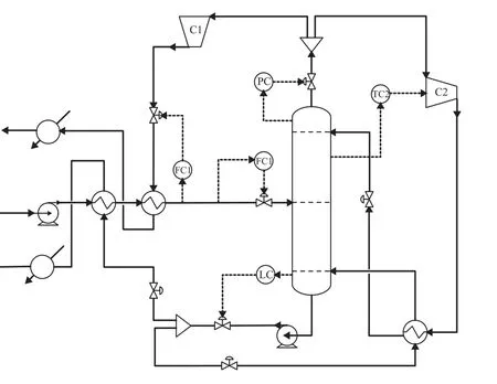
Figure 8 Basic control structure of the SHRD process
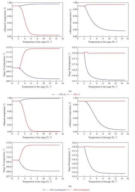
Figure 9 Dynamic responses of the SHRD process for the basic control structure with ±10% disturbances in (a) feed flow rate; (b) feed composition
To overcome the defects of the basic control structure, this low relative volatility system requires the use of dualtemperature control. An improved control structure for the SHRD design is proposed after a lot of control structures have been investigated following continuously explored efforts. Based on the original control structure, another temperature controller TC3 is added to control the tray temperature of the stage 50 as shown in Figure 10, which is adjusted by the ratio of boilup rate to feed flow rate (B/F). The sequential iterative tuning procedure is used to tune the temperature controllers[19].

Figure 10 Improved control structure of the SHRD process
Figure 11 reveals the simulation results of the SHRD process with the improved control structure for ±10% feed disturbances. As shown in Figure 11, the temperature control point of the stage 22 is able to quickly return back to its setpoint. Although the settling time is relatively long when the SHRD system is adapted to a 10% increase in iso-butanol content of the feed composition, the temperature responses of the stage 50 are all able to hold fairly close to their setpoints, which leads to the improvement in n-butanol quality. Judging from the closed-loop responses, it can be seen that the improved control strategy with the B/F ratio can handle different feed disturbances effectively. Moreover, the SHRD system with the improved control scheme can achieve stability faster than with the basic one. Therefore, the improved control structure is suitable for this SHRD process.
4 Conclusions
The self-heat recuperative distillation is an attractive technology used in the separation process. In this work, the conventional distillation process, VRC process and SHRD process are investigated for the separation of n-butanol and iso-butanol mixtures. The optimum design is obtained by minimizing the TAC, and the results show that, for the SHRD process, 37.74% and 11.35% reductions in TAC can be obtained compared with the conventional distillation process and VRC process, respectively.
The dynamic characteristics of this SHRD system are investigated, and two control structures are proposed for the optimum SHRD design. The dynamic responses reveal that the SHRD process with the basic control structure can barely bring the product purity to their setpoints. Therefore, in order to control the system effectively, an improved control structure with dual-temperature control is proposed. It is shown that with the improved control structure, the SHRD system can handle various feed disturbances effectively, and the high-purity products can be obtained.
Acknowledgements:Financial supports from the National Natural Science Foundation of China (Grant: 21276279 and Grant: 21476261) and the Fundamental Research Funds for the Central Universities (No. 14CX05030A; No. 15CX06042A) are acknowledged with gratitude.
[1] Halvorsen I J, Dejanović I, Skogestad S, et al. Internal configurations for a multi-product dividing wall column[J]. Chemical Engineering Research and Design, 2013, 91(10): 1954-1965
[2] Wu Y C, Lee H Y, Huang, H. P, et al. Energy-saving dividing-wall column design and control for heterogeneous azeotropic distillation systems[J]. Industrial & Engineering Chemistry Research, 2014, 53(4): 1537-1552
[3] Kiran B, Jana A K. Introducing vapor recompression mechanism in heat-integrated distillation column: impact of internal energy driven intermediate and bottom reboiler[J]. AIChE Journal, 2015, 61(1): 118-131
[4] Waheed M A, Oni A O, Adejuyigbe S B, et al. Performance enhancement of vapor recompression heat pump[J]. Applied Energy, 2014, 114: 69-79
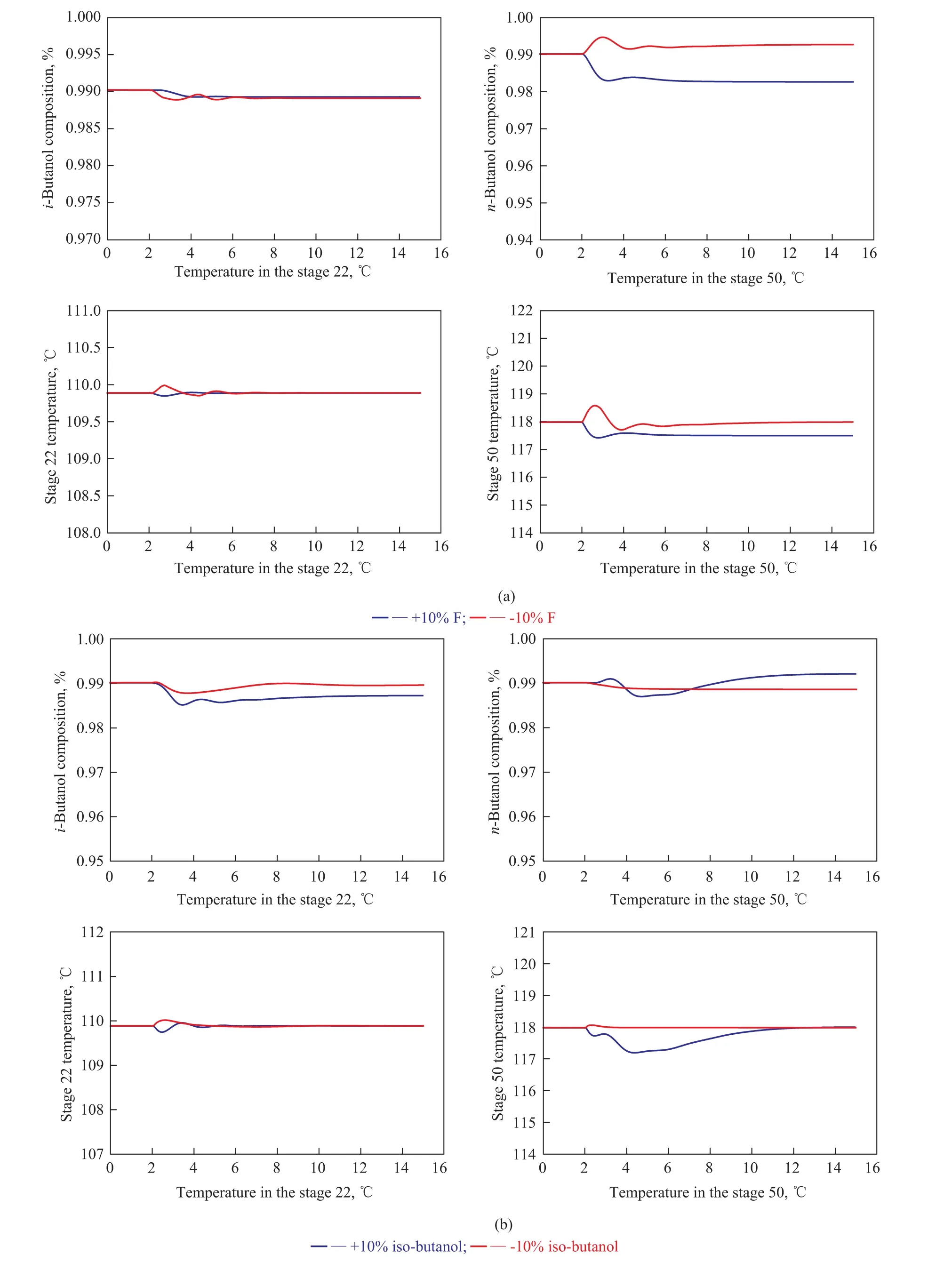
Figure 11 Dynamic responses of the SHRD process for the improved control structure with ±10% disturbances in: (a) feed flow rate; (b) feed composition
[5] Suphanit B. Optimal heat distribution in the internally heatintegrated distillation column (HIDiC)[J]. Energy, 2011, 36(7): 4171-4181
[6] Bruinsma O S L, Krikken T, Cot J, et al. The structured heat integrated distillation column[J]. Chemical Engineering Research and Design, 2012, 90(4): 458-470
[7] Kansha Y, Tsuru N, Sato K, et al. Self-heat recuperation technology for energy saving in chemical processes[J]. Industrial & Engineering Chemistry Research, 2009, 48(16): 7682-7686
[8] Kansha Y, Tsuru N, Fushimi C, et al. New design methodology based on self-heat recuperation for production by azeotropic distillation[J]. Energy & Fuels, 2010, 24(11): 6099-6102
[9] Kansha Y, Tsuru N, Fushimi C, et al. Integrated process module for distillation processes based on self-heat recuperation technology[J]. Journal of Chemical Engineering of Japan, 2010, 43(6): 502-507
[10] Kansha Y, Tsuru N, Fushimi C, et al. An innovative modularity of heat circulation for fractional distillation[J]. Chemical Engineering Science, 2010, 65(1): 330-334
[11] Kansha Y, Kishimoto A, Tsutsumi A. Process design methodology for high-energy saving HIDiC based on self-heat recuperation[J]. Asia-Pacific Journal of Chemical Engineering, 2011, 6(3): 320-326
[12] Matsuda K, Kawazuishi K, Hirochi Y, et al. Advanced energy saving in the reaction section of the hydro-desulfurization process with self-heat recuperation technology[J]. Applied Thermal Engineering, 2010, 30(16): 2300-2305
[13] Matsuda K, Kawazuishi K, Kansha Y, et al. Advanced energy saving in distillation process with self-heat recuperation technology[J]. Energy, 2011, 36(8): 4640-4645
[14] Gao X, Chen J, Ma Z, et al. Simulation and optimization of distillation processes for separating a close-boiling mixture of n-butanol and isobutanol[J]. Industrial & Engineering Chemistry Research, 2014, 53(37): 14440-14445
[15] Kansha Y, Kishimoto A, Tsutsumi A. Analysis of dynamic characteristics for self-heat recuperative process[J]. Chemical Engineering Transactions, 2012, 29: 307-312
[16] Sun L, Wang Q, Li L, et al. Design and control of extractive dividing wall column for separating benzene/cyclohexane mixtures[J]. Industrial & Engineering Chemistry Research, 2014, 53(19): 8120-8131
[17] Douglas J M. Conceptual Design of Chemical Processes[M]. New York: McGraw-Hill: 1988
[18] Luyben W L. Plantwide Dynamic Simulators in Chemical Processing and Control[M]. New York: Marcel Dekker: 2002
[19] Huang H P, Jeng J C, Chiang C H, et al. A direct method for multi-loop PI/PID controller design[J]. Journal of Process Control, 2003, 13(8): 769-786
Trial Production of Needle Coke at Shanghai Petrochemical Company
Needle coke is the starting material for manufacture of premium graphite electrode, which at present cannot be produced by SINOPEC and even other domestic refining enterprises so that the carbon producing plants inside China have to import a significant amount of high-quality needle coke every year. The project “Production of premium needle coke and development of engineering techniques” jointly undertaken by the SINOPEC Research Institute of Petroleum Processing and the SINOPEC Shanghai Petrochemical Company Limited (SPCL) after completion of the preparative stages involving distillation of slurry oil and hydrodesulfurization of slurry fractions on July 10, 2015 began to enter into the commercial-scale coking test phase. Till July 18, 2015, the test team has performed four operating cycles, and the first stage of trial coking had manufactured a total of 1800 tons of coke, the properties of which are being investigated. The said commercial tests were carried out in the 1.0 Mt/a delayed coking unit at SPCL. In the course of commercial tests there were a lot of difficulties related with control over the operation of equipment because of the drastic changes in production process conditions, and any malfunction could result in tower flooding or coking inside the heating furnace. The technical personnel of RIPP have been working cooperatively to formulate emergency response measures while making directives and instructions to secure the safe and smooth operation of the process unit.
date: 2015-08-03; Accepted date: 2015-09-09.
Prof. Sun Lanyi, Telephone: +86-13854208340; Fax: +86-532-86981787; E-mail: sunlanyi@upc.edu.cn.
杂志排行
中国炼油与石油化工的其它文章
- Numerical Simulation of Enhanced Oil-Water Separation in a Three-Stage Double-Stirring Extraction Tank
- Computational Fluid Dynamics Simulation of Liquid-Phase FCC Diesel Hydrotreating in Tubular Reactor
- Promotional Effect of CoO(OH) on Selective Hydrogenation of Maleic Anhydride to γ-Butyrolactone over Supported Ruthenium Catalyst
- Microbial Characterization of Denitrifying Sulfide Removal Sludge Using High-Throughput Amplicon Sequencing Method
- Hydrothermal Liquefaction of Wheat Straw in Sub-critical Water/Ethanol with Ionic Liquid for Bio-oil Production
- Quantitative Analysis Using Fourier Transform Ion Cyclotron Resonance Mass Spectrometry and Correlation between Mass Spectrometry Data and Sulfur Content of Crude Oils