数字多点系统拓扑网络结构识别的设计与实现
2015-06-08徐年丰王业通
徐年丰,王业通,赵 霞
(1.上海华太数控技术有限公司,上海201801;2.同济大学电信学院,上海201804)
1 Introduction
With the rapid development of information technology,data communication network and mobile data communication has become an indispensable part of people's daily lives.But there always exist some weak signal areas or blind spots in communication.In order to improve the signal quality,a series of digital stations or repeaters usually set up in these areas.Compared with a base station,a repeater has advantages of lower cost,shorter constructing time and higher overlay quality.Mobile data can be transmitted through repeaters to improve the coverage efficiency.Digital repeater system is designed to improve the quality of mobile communications inside buildings[1].
In order to highlight the features such as the flexible networking,multi-point coverage and antiinterference performance,a digital repeater system can be considerably extended with numbers of remote cascade devices.The system consists of three parts:Multi-source Access Unit(MAU)、Extended Unit(EU)and Remote Unit(RU)[2].As shown in figure 1,MAU converts the RF source signal to digital signal and pulls away to the Extended Unit by optical fiber.The numbers of remote cascade devices.The maximum amount of Extended Units rooted to MAU is eight.Through EU,the digital signal is converted to eight channels of digital signal.The digital signal is transferred to Remote Unit by cable of Cat 5.Finally,RU converts the digital signal to RF signal and transmits out[3].

Fig.1 Equipment plan for a digital repeater system
Due to its simple installation and use,the repeater equipment is distributed widely.It is inconvenient to get access to the field if there are some parameters should be changed on the system.The stability and reliability is a key problem for a repeater system.So the repeater monitoring system is an important part in monitoring,operating state and remote control.The system has experienced several stages from simple local test to basic remote monitoring system;finally take shape of the united network management today.The united network is shown in figure 2;OMC(Operation and Maintenance Center) communicates with NMC (network management center)through northbound interface,and communicates with different kinds of repeaters through southbound interface.The channels of southbound interface consist of Ethernet network,SMS(short message service)and GPRS(General Packet Radio Service)network[4].

Fig.2 United Network Management systems
To monitor any device in the digital repeater system,OMC should recognize every device’s login address.The topology management helps identify the topology structure and transmits the information to OMC by frames.Each monitoring frame packs a login address number for each device.MAU gets the address number and makes a path search based on the topology structure,sending the frame to the target device[5].So it is crucial to get the latest and stable topology for the real-time variation.This paper will analyze the possible topology structure;propose a design of topology management scheme in section 2.The management scheme consists of some data structures and a schedule of internal communication between devices.In section 3,a process of dynamic management assignment and remove will be illustrated.A method of interaction with OMC will be proposed and the topology management experimental result will be displayed in section 4.
2 Design of topology management
scheme
As shown in figure 3,the topology structure of the devices in the system has two different types.One is star-like structure like EU1 which has no extended devices and the other is chain-like structure which is used to expand the scope of the signal coverage,like EU4 and EU5(we define EU4 as the parent device of EU5).For the star-like structure,MAU can determine which device is in place by polling strategy.After de-wobbling function which is realized by scheduled scan using a timer,MAU begins to assign a topology address for the new device.In order to ensure the reliability of assignment,a“three-way handshaking”mode is employed into the process,which will be explained in section 3.1.For the chainlike structure,EU5 cannot communicate with MAU directly.The information will be forwarded to MAU by its parent EU.But as the number of cascade devices grows,the depth of the cascade increases.The message between two ends will be transformed step by step.In order to improve the efficiency of communication,no more procedures will be done by the middleware.They just do some necessary simple process and forward the message to the terminal equipment,which will be explained in section 3.2.

Fig.3 Topology network structure of a digital repeater system
In view of the two kinds of structure in the system,the scheme has two different strategies to recognize the topology state of devices in the system.The rolling strategy is used to recognize the state of the root EU.If the dynamic device is not a root EU,the topology management is realized by initiative reporting which is an effective way.The devices communicate within the system by the internal messages.All the information will be put together on MAU,ready to be sent to OMC.
2.1 Data structure of topology management
All the states of devices will be stored on the MAU device which is the top device of the system.The maximum topology address available is up to 255.All the available address states are stored by bitmaps.Based on the bitmap,the system can calculate a given topology address for a given device.Obviously,the bitmap scheme can save lots of memory space and fit to the embedded system.In the bitmap,the bit 1 stands for allocated address and bit 0 stands for the available address.The maximum memory space has to be maintained is only 32 bytes.
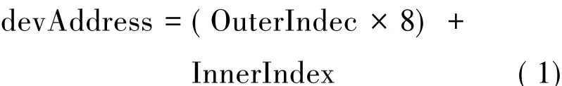
Once a new device is on place,the topology management will search the bitmaps from low bit to high bit to look for an available bit.If there is no bit available in the bitmaps,it means the equipment number has exceeded the maximum available range.If the bit 0 is found in the bitmap,a new topology address(devAddress)can be calculated based on the position of the bit(OuterIndex,the byte catalogue and InnerIndex,the bit offset in one byte)as it shows in Formula 1 and then set the available bit to bit 1.In the multi-task software system,a mutual lock should be introduced to protect the sharing memory space.So in the topology management a lock should be used when operating the bitmap.
For extendable EU devices,it is a better scheme to adopt the linked list data structure to describe.The linked list has the features of variable length and it is convenient to insert and delete any elements in the list in no need of moving each element.In our definition,the EU device linked list has such elements,root device address,parent EU device address,depth of the current EU device,the state of assignment and the port state.
2.2 Internal communication
As figure 4 shows,every device carries an ARM processor and a FPGA chip.All the physical layer data will be handled by FPGA,including clock synchronization,port state polling,data receiving and sending.FPGA offers an OAM interface to ARM processor.ARM and FPGA interacts with each other by OAM interface.The interface consists of a receiving channel and a sending channel,each channel has a set of control register,data register and state register.All the software design is realized based on the interface.
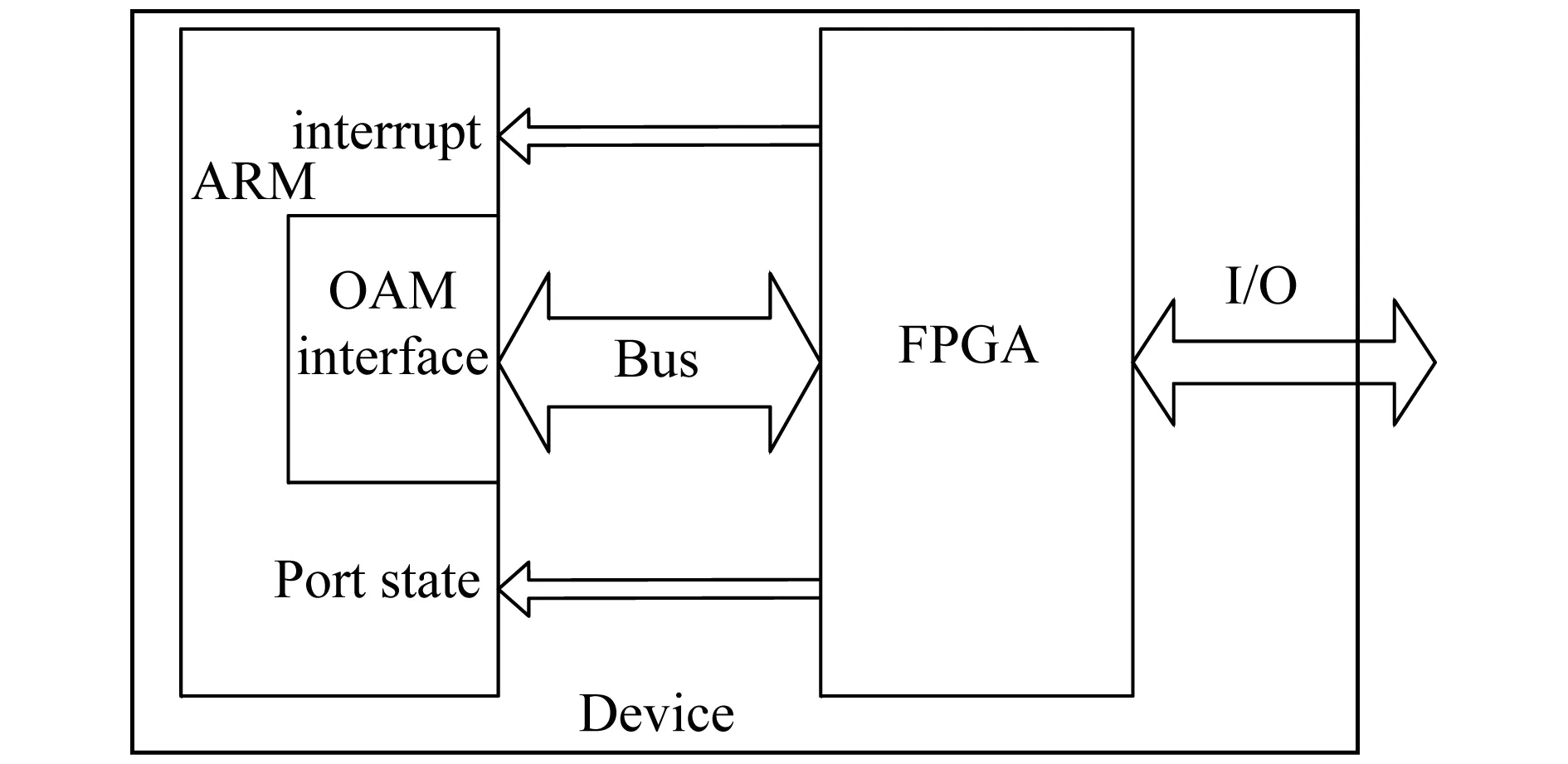
Fig.4 OAM interface within the system
The software design adopts a multi-task mechanism.In order to keep the real-time performance,the task schedule adopts the preemptive scheduling strategy.The priority of each task is determined by its correlation with asynchronous interrupt request and the order of stream[6].For the message to be received or sent,the software scheme provides a buffer mechanism to control the traffic of incoming and outgoing.To support the buffer mechanism,a memory management scheme should be given to limit the memory fragments which usually caused by a lot of small packets memory allocation and memory de-allocation[7].
As shown in figure 5,the memory management can supply a given length memory buffer for every internal message.In our application,the length is 1024 bytes.The memory management applies for a memory buffer in the memory pool ahead of time.If the maximum of the messages number is N,the Memory management should apply for 1024*N bytes memory space.Then the software creates a circle buffer,in which the memory address available for each message is stored.When receiving message,the user can get a memory address from the circle buffer and set the address unavailable.When sending message,the user can restore the memory address into the circle buffer and set the address available again.All the control process is realized by controlling index of the circle buffer.

Fig.5 Circle buffer of the memory management
The software adopts the interrupt mode to handle the message receiving process.Once receiving an interrupt signal,the processor will request for the state of the OAM interface to FPGA and receive the data by byte or word from the data register until the length of the data reaches the content of the length register.After verifying the form of the data legal,the receive task send the message to message queue ready to be handled by the message process task.In order to realize“zero copy”in the process of handling message,the scheme designed a structure pointer which is applied to the layered protocol.By passing and handling on the pointer,the process can avoid copying the data repeatedly.It is easier to send message for the software.Before sending messages,the processor checks the enable state of the port from the OAM interface state register.If the given port is send-enabled,the processor writes the data to the data register and control register to start the time series of the interface.FPGA gets the data and sends it to the physical layer.Then the data will be sent to the other device by optical fiber or cable-cat5.
The topology information should be packed in the message according to the internal protocol which is used to determine the source device and the destination device.The packed form of the information adopts the layer protocol.All the information about topology will be packed in the application layer which is top layer of the protocol.The details of the message protocol can be found in the reference 3.
3 Dynamic management process
3.1 Three-way handshaking strategy
In the initial stage of device connection,the state of connection is not stable.Therefore the synchronization clock between devices is not stable and the message between devices in this period is not reliable.There may be some wrong data or some length error in the message.In order to confirm the stable state of connection,a software de-wobbling function is applied in the process.After the processor confirmed the new device is on place,MAU checks the bitmaps for an available bit and calculates the topology address for the new device according to formula 1,ready to start the assignment process.In order to ensure the reliability of the assignment process,the scheme adopts a “Three-way handshaking”strategy.Only after all the three-way processes are done,can the assignment process accomplished.As figure 6 shows, the first handshaking is from MAU to new EU,which is an address assignment process.The second handshaking is the assignment response from new EU and EU waits for verification.After the third handshaking which is the verify command from MAU to EU,MAU confirms that the assignment is done.EU confirms its own address and makes it ready to handle any messages sent to it.
3.2 Dynmic connection and disconnection
If the new device is not a root EU which is connected to MAU,the topology management is realized by initiative reporting which is an effective way.As figure 7 shows,once a new EU connects to its parent device,the parent device will immediately send a report message to MAU which is the port state change alarm message.Just as the root device assignment,MAU calculates the topology address for the new device and make the address assignment process.The parent device just forwards the message between the two terminals.After receiving the response from the new device,the assignment process is done and MAU should update the new topology structure,such as adding the new linked node to the device linked list of the root port,maintaining bits in the bitmaps,giving a plus to the device number and the depth of the cascade.
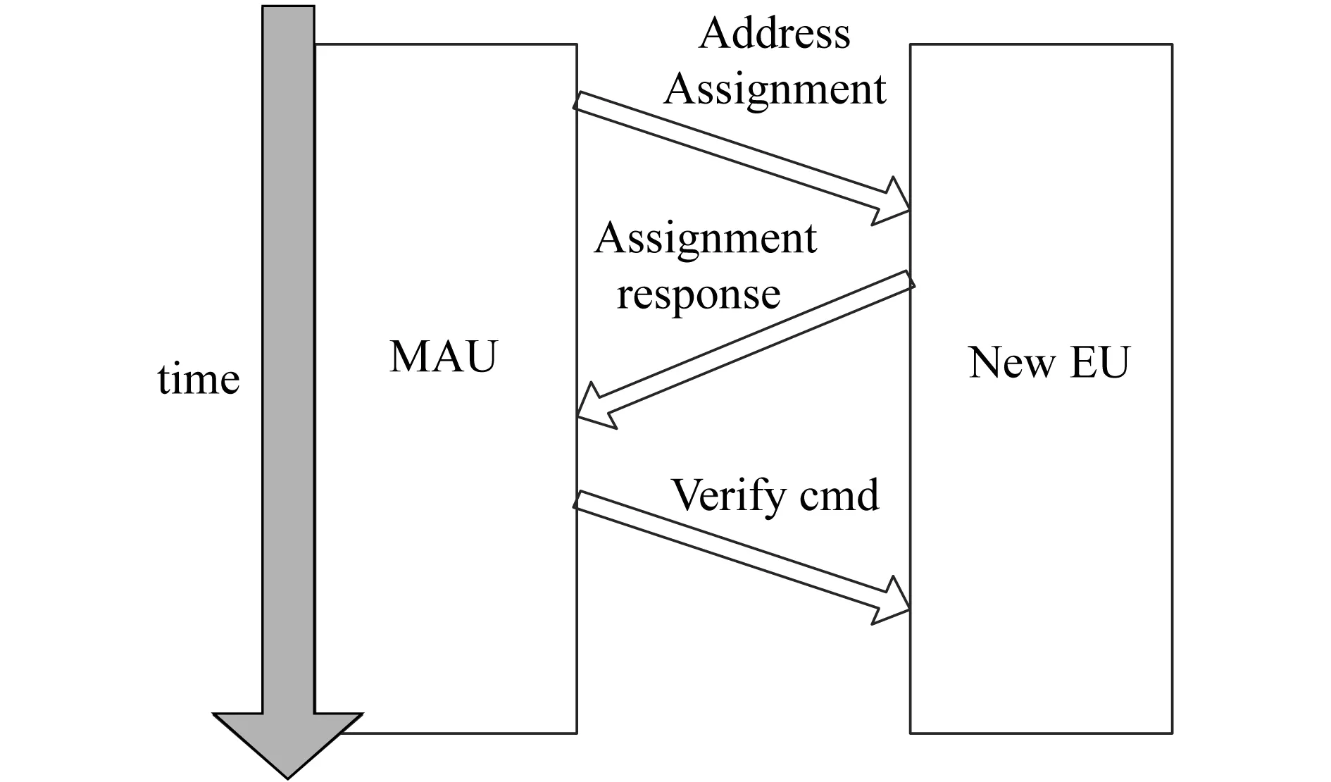
Fig.6 Three-way handshaking strategy
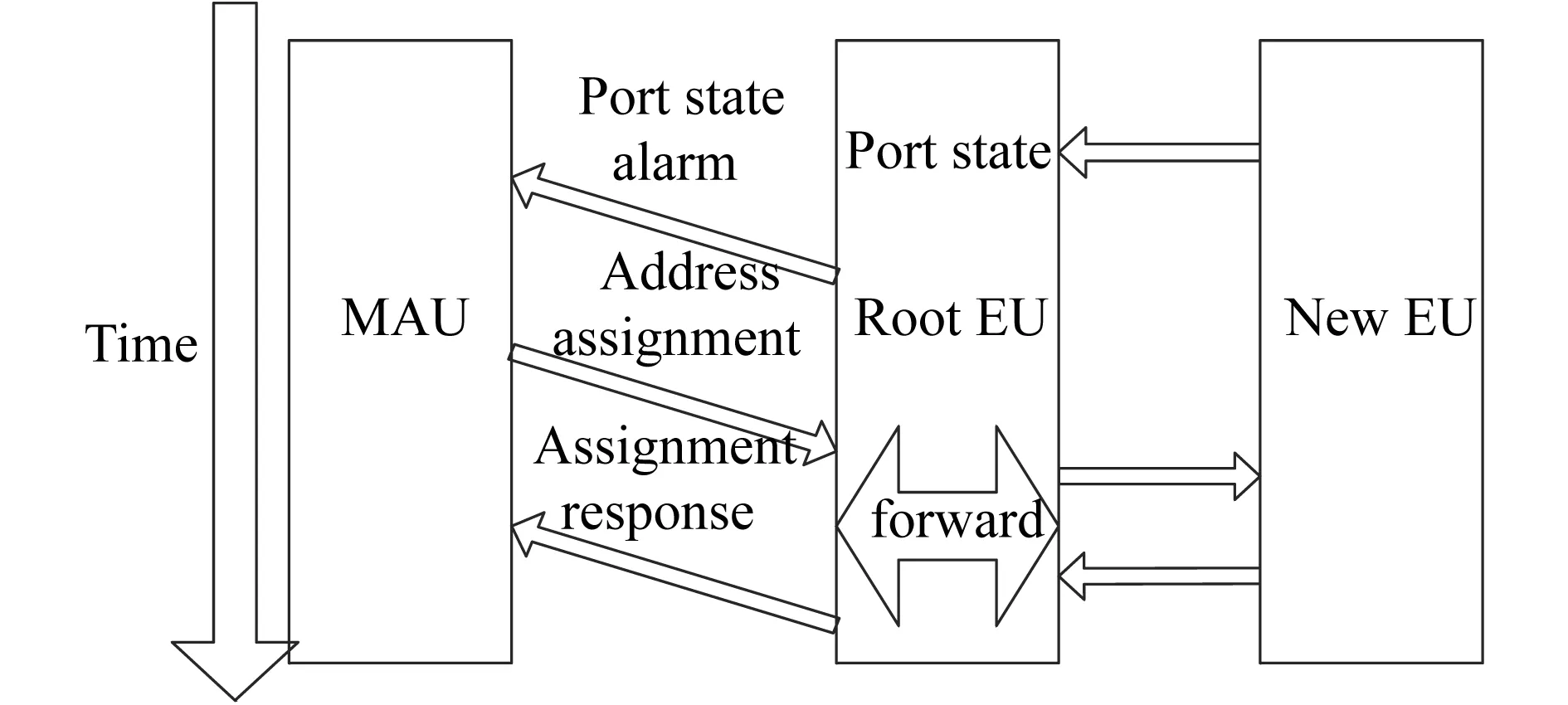
Fig.7 Dynamic connection assignment processes
On the contrary to the dynamic connection,as figure 8 shows,once a cascade EU disconnects with its parent device,the parent device will immediately send a report message to MAU which is the port state change alarm message.By analyzing the data packed in the message,MAU detects the state of port not linked and just give a response to the parent EU.MAU should update the new topology structure,such as deleting the linked node from the device linked list of the root port,maintaining bits in the bitmaps,giving a minus to the device number and the depth of the cascade.

Fig.8 Dynamic disconnection
4 Result
By the topology management explained above,all the topology network information of the system has been stored on the top equipment MAU.From section 1.2,the monitoring plan for the digital repeater,to monitor any device in the repeater system,the OMC should recognize every device’s login address.So how to pack the information in the sending message in an efficiency way is a problem.This section proposed a layered packed frame structure,shown in figure 9.The structure makes full use of space to pack all the topology network information in one frame.The information can be efficiently obtained by hierarchical processing.
An experimental result is shown here.We used a PC as the OMC and connected multiple devices in the digital repeater system.Using upper-supervision software,the OMCgets the data shown in table 1 and displays the result of the topology network in figure 10 according the frame structure.

Fig.9 Frame structure of topology information packed

Tab.1 Frame structure of topology information
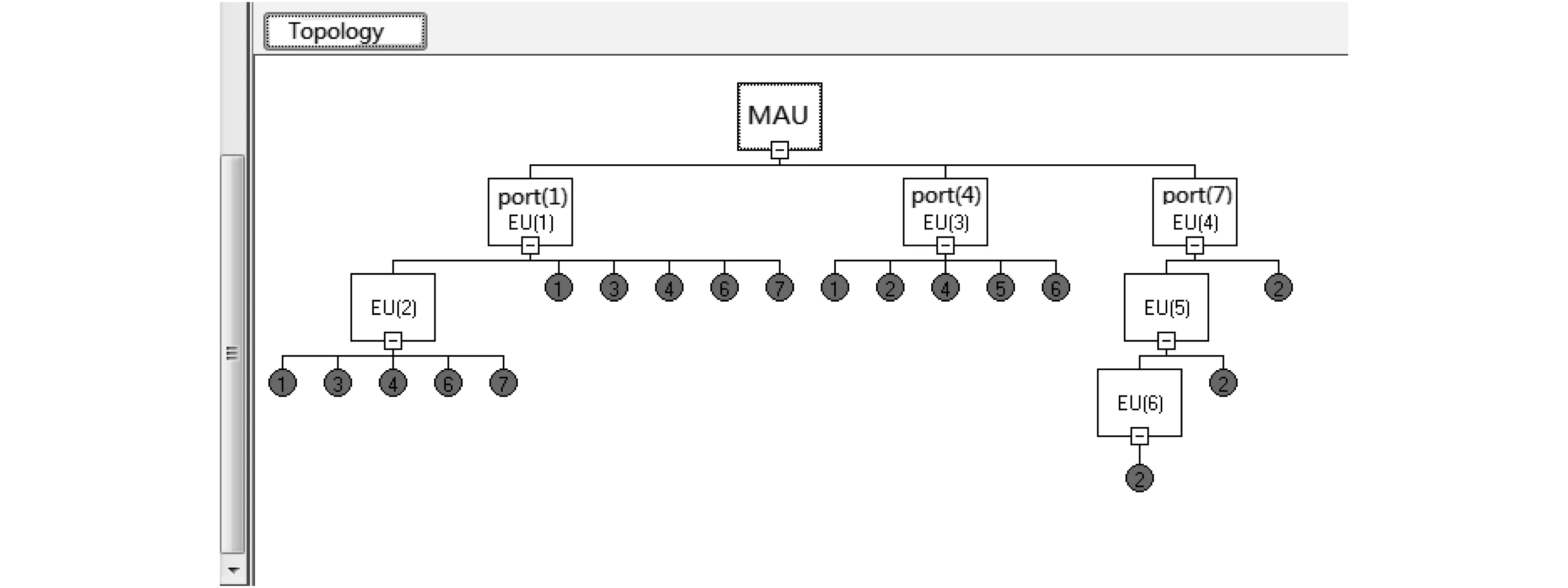
Fig.10 Topology network result displayed on OMC
5 Conclusion
This paper proposed a designed scheme of dynamic topology network structure identification to adapt the diversity of the network topology structure and the real-time variation.This design has been proved accurate to identify the system's network topology,not only for star structure but also chain structure for universal.It can enhance the stability and accuracy of the identification process.It also gives a way to communicate with remote monitor via Ethernet.After the remote monitor gets the network topology,it realizes to control any devices in the system by employing each device’s topology login address.
[1] 林海鹏.数字光纤直放站的特点及应用[J].通信与信息技术,2011(4):81-83..LIN Haipeng.The characteristic and application of digital optical fiber repeaters[J].Communication and Information Technology,2011(4):81-83.
[2] 李自刚.基于ARM和GPRS的光纤直放站监控系统的设计与实现[D].武汉:武汉理工大学,2009.LI Zigang.The design of optical fiber repeater monitoring system and implementation based on GPRS and ARM[D].Wuhan:Wuhan University of Technology,2009.
[3] 中国移动通信有限公司.中国移动直放站监控系统功能规范 1.0[S].[地址不详]:中国移动通信有限公司,2005.China Mobile Communication Co.Ltd.Mobile repeater monitoring system specification 1.0[S].[s.l.]:China Mobile Communication Co.Ltd,2005.
[4] 王亚丽.直放站网管系统的现状与发展分析[J].移动通信,2004(5):98-100.WANG Yali.The situation and development of mobile communication network management system of repeater station analysis[J].Mobile Communication,2004(5):98-100.
[5] 中国移动通信公司.QB-W_004-2005中国移动直放站监控系统功能规范[S].[地址不详]:中国移动通信有限公司,2005.China Mobile Communication Co.Ltd.QB-W_004-2005.China Mobile repeater monitoring system function specification[S].[s.l.]:China Mobile Communicatioin Co.Ltd,2005.
[6] Labrosse Jean J.嵌入式实时操作系统 μCOS-Ⅱ[M].邵贝贝译.北京:北京航空航天大学出版社,2003.Labrosse Jean J.Embedded real-time operating system COS-II[M].Translated by SHAO Beibei.Beijing:Beihang University Press,2003.
[7] 王苗田.嵌入式系统设计与实例开发[M].北京:清华大学出版社,2002.WANG Miaotian.The design and development of embedded system[M].Beijing:Tsinghua University Press,2002.