Designing the cooling system of a hybrid electric vehicle with multi-heat source
2015-04-24WANGRui王瑞WANGYichun王义春FENGChaoqing冯朝卿
WANG Rui(王瑞), WANG Yi-chun(王义春), FENG Chao-qing(冯朝卿)
(1.School of Mechanical Engineering, Beijing Institute of Technology, Beijing 100081, China; 2.College of Mechanical Engineering, Inner Mongolia University of Technology, Hohhot 010051, China)
Designing the cooling system of a hybrid electric vehicle with multi-heat source
WANG Rui(王瑞)1,2, WANG Yi-chun(王义春), FENG Chao-qing(冯朝卿)1
(1.School of Mechanical Engineering, Beijing Institute of Technology, Beijing 100081, China; 2.College of Mechanical Engineering, Inner Mongolia University of Technology, Hohhot 010051, China)
In order to reduce the power consumption and meet the cooling demand of every heat source component, three kinds of multi-heat source cooling system schemes were designed base on the characteristic of power split hybrid electric vehicle (HEV). Using the numerical simulation method, the power system heat transfer model was built. By comparing the performance of three different schemes through the Simulink simulation, the best cooling system scheme was found. Base on characteristics of these cooling system structures, the reasonableness of the simulation results were analyzed and verified. The results showed that the cooling system designation based on the numerical simulation could describe the cooling system performance accurately. This method could simplify the design process, improve design efficiency and provide a new way for designing a multi-heat source vehicle cooling system.
hybrid electric vehicle (HEV); numerical simulation; multi-heat source; oil-cooled brake resistor; cooling system design
Compared to traditional propulsion systems, a hybrid electric vehicle (HEV) has many advantages such as improved fuel economy, better acceleration performance, low acoustic signature and exportable electric power. So it is suitable for a heavy duty vehicle. However, the HEV need additional components such as generator, drive motor, power bus, battery and brake resistor, all of which increase the heat release and require more power and proper thermal management. The cooling systems of the HEV become complicated because the target temperatures of every heat source are different. The cooling system of the HEV needs more sensors, controllers, and a cooling circuit. In order to adopt the cooling mode combined by a variable speed electric fan and cooling circuits, a hybrid vehicles cooling system structure should be designed carefully to ensure the efficient work of the pumps and fans. Due to the complexity of the HEV cooling system and flexibility in designing the system, numerical modeling is an efficient way to assess various design concepts and architectures of the system during the early stage of system development[1]. Traci and Acebal demonstrated that a numerical approach could be used for the thermal management system design of HEV[2]. Park and Juara used numerical simulation software to analyze the thermal characteristics of a hybrid vehicle engine compartment[3]. Park.S and Jung finished a comprehensive study about HEV cooling system by MATLAB[4].
Studies of the HEV cooling system focus on cooling demand, power consumption, temperature stability of heat source components and control mode. Cooling system containing oil-cooled brake resistor is the innovation point and high light of this paper. Cooling system simulation is done base on the work mode provided by a control strategy. Performance and power consumption of several different cooling system structures are compared by numerical simulation and the most suitable cooling system for the HEV with braking resistor is got in this study.
1 Modeling cooling system
The HEV propulsion system is composed by engine, generator, bus controller, motor, battery pack, speed increasing device and gearbox (Fig.1).
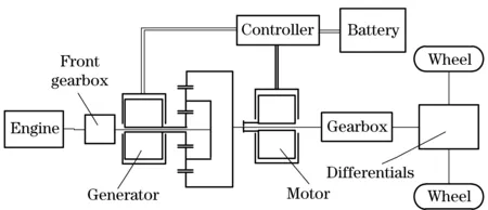
Fig.1 Schematic of the HEV propulsion system
The cooling system is designed based on a power split HEV propulsion system developed by Xiang Changle[5]. The specifications of the HEV simulated in this study are summarized in Tab.1.

Tab.1 Specification of the HEV
As shown in Tab.2, each heat source component has its own control target temperature, which is the maximum allowable temperature that should be maintained by the cooling system.

Tab.2 Control target temperatures of power components
1.1 Heat source component model
In the HEV, an internal combustion engine, a generator, drive motors, a power bus and an oil-cooled brake resistor are the heat source components. Lumped thermal mass model is used for the temperature calculation of all heat source components[6]. In the model, the average temperature of the component is calculated from the balance of heat generation by the components, heat transfer to the coolant, and heat transfer to the ambient. Thus, the component temperature change is calculated from
(1)
qi=hAi(Tc-Tco)
(2)
(3)
whereTcis temperature of component,Tcois temperature of coolant,Teis external temperature,qcis caloric of component,qiis internal energy,qeis external energy,tis time,ρis density,CPis specific heat capacity,his convection heat transfer coefficient,Aiis internal area,Aeis external area, andσis Stefan-Boltzmann constant. Heat generation of the engine is calculated based on the performance map. Fuel consumption rate curve of engine is shown as Fig.2.

Fig.2 Fuel consumption rate curve of engine
Heat generations by the generator and motor are calculated based on their efficiencies. The heat generation from the generator and motor is calculated as
qg=τgωg(1-ηg)
(4)
(5)
whereqgis the heat of generator,τgis torque of generator,ωgis speed of generator,ηgis efficiency of generator,qmis the heat of motor,τmis torque of motor,ωmis speed of motor, andηgis efficiency of motor. The motor also works as an electric generator during braking mode. The heat generation from the motor during regenerative braking is calculated with
qm=|τmωm|(1-ηm)
(6)
The heat generated by the power bus is calculated based on the power delivered by the power bus and the efficiency of the power bus. The power delivered by the power bus is determined based on the power management mode which will be described in the vehicle simulation section. Therefore, the heat generated by the power bus is determined by total powerPp
qp=Pp(1-ηp)
(7)
wherePpis power in bus,qpis heat generate in power bus, andηpis efficiency of power bus. In braking mode, the heat generated in break resistor is calculated as
qb=τmωmηmηp-VI
(8)
Heat generated in gearbox is calculated with
qg=τwωw(1-ηg)
(9)
whereVis charge voltage,Iis charge current,qgis heat generated in gearbox,qbis heat generated in resistor,τwis torque of wheel,ωwis the rotor speed of wheel, andηgis efficiency of gearbox.
Pressure drop across each heat source component is calculated as pump loss. Coolant pressure drop across the component is calculated by assuming that the coolant path in the component is a smooth pipe and the pressure drops across the components are calculated as
Laminar:
(10)
Turbulent:
(11)
whereΔpis pressure drop,μis dynamic viscosity,Lis the length,vis velocity, anddis diameter.
1.2 Radiator heat transfer model
Thermal resistance concept based 2-dimensional finite difference method (2-D FDM) is used to model the radiator[7]. Various parameters of the heat exchanger can be designed and predicted by the numerical model. The same model is also used for the charge air cooler, oil radiator and brake resistor radiator. Number of transfer units (NTU) for the heat exchanger is calculated from[8]
(12)
The effectiveness of the heat exchanger is calculated as
(13)
The heat transferred in the radiator is
q=εcmin(Th,i-Tc,i)
(14)
whereNis the number of transfer units,Uis overall transfer coefficient,Ais area,Cis specific heat capacity,criscmin/cmax,Th,iis the inlet temperature of hot fluid, andTc,iis the inlet temperature of cool fluid.
1.3 Medium heat transfer model
Heat in the cooling system are delivered to environment through cooling medium, the cooling medium circulation is mainly dependent on the pump and fan. The servo motors are used to drive the fan and pump, whose speed can be changed base on the temperature of each heat source component to make sure that the cooling system power consumption is the least when all components are in the best working temperature. The pumps and coolant flow model is
v=f(Np,ΔPp)
(15)
The fans and cooling air flow model is
v=f(Nf,ΔPf)
(16)
whereNpis speed of pump,Nfis speed of fan, ΔPpis pressure jump of pump, and ΔPfis pressure jump of fan.
2 Architecture design of a cooling system
The cooling system of the HEV has many characteristic such as multiple heat source components, different working temperature and working time not synchronized. So the structural design of the cooling system has a variety of solutions. The design schemes of the cooling system should be optimized to achieve the highest efficiency. Base on the characteristic of power split HEV, three different cooling system schemes are designed as shown in Fig.3.
The coolant flow rates to the by-pass circuit and to the radiator circuit are determined at the pressure drops through each circuit and performance of pumps. Similar with the coolant, the cooling air flow rates are determined at the pressure drops and the performance of fans. Flow resistances of cooling air are influenced by grille, radiators, fan and pipe line.
Cooling fan power consumption is proportional to the air flow rate and static pressure, performance test curve of axial fan is shown in Fig.4.
The fan speed is controlled base on the cooling air needed for cooling system. Control strategy of cooling fan is related to many parameters inclu-ding environment temperature, battery power condition and vehicle driving condition (including speed, acceleration and gradient)[9].
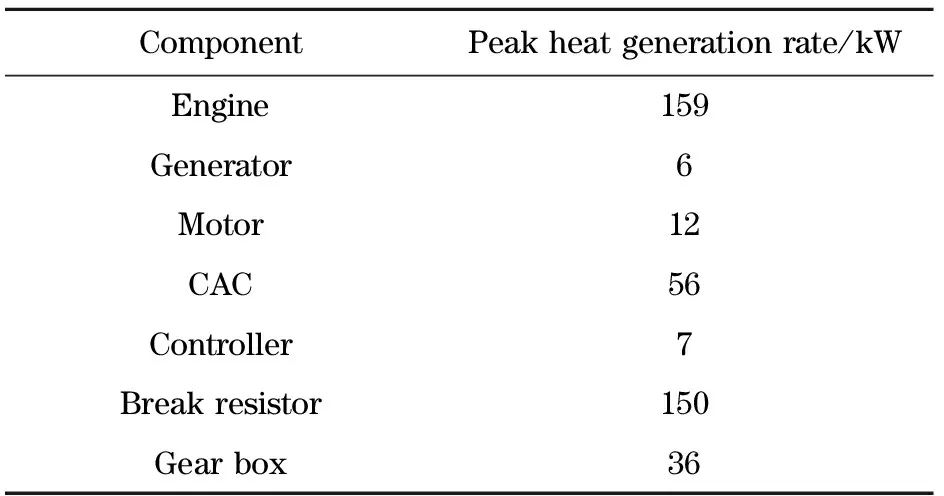
The size of the radiator is determined by the cooling air flow and maximum heat transfer. Maximum heat generation power of each part is shown in Tab.4
Radiators sizes are determined based on the maximum heat generation power of each part and the spatial structure characteristics of power cabin and layout position, as shown in Tab.5.
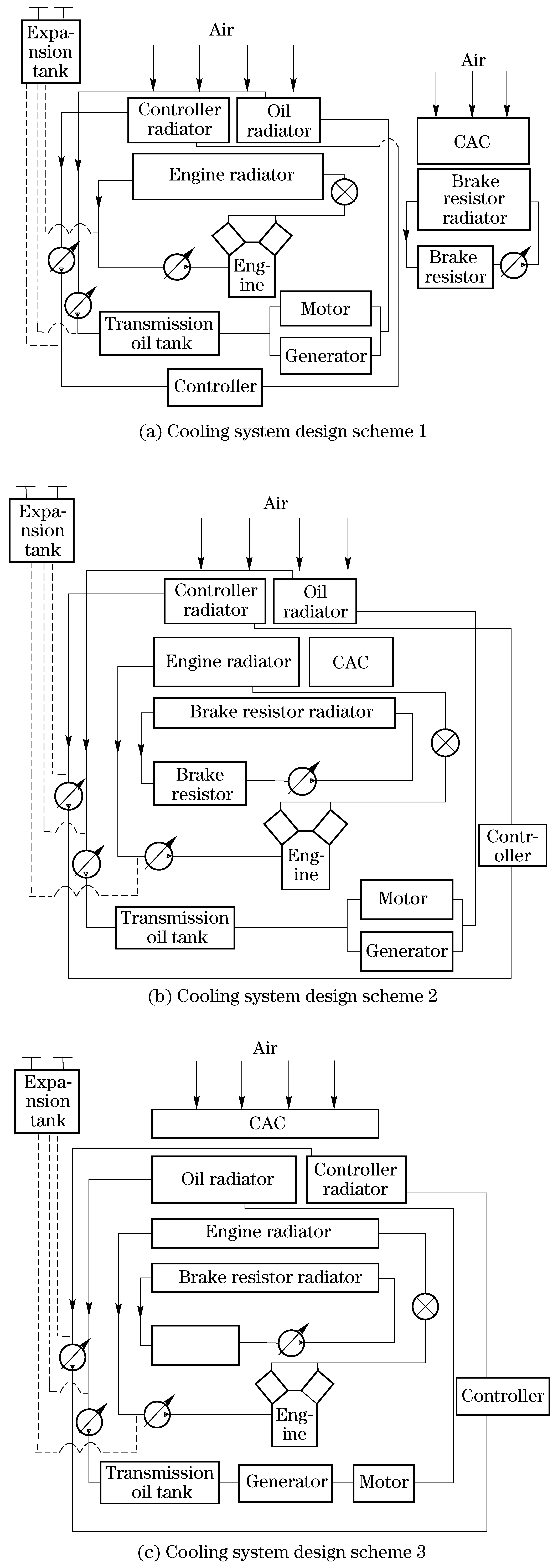
Fig.3 Three kinds ofcooling system design scheme

Fig.4 Performance test curve of axial fan
Tab.4 Maximum heat generation power of each part
ComponentPeakheatgenerationrate/kWEngine159Generator6Motor12CAC56Controller7Breakresistor150Gearbox36
Vehicle driving condition which used in cooling system simulation is shown in Fig.5.

Tab.5 Radiator size of the cooling system mm
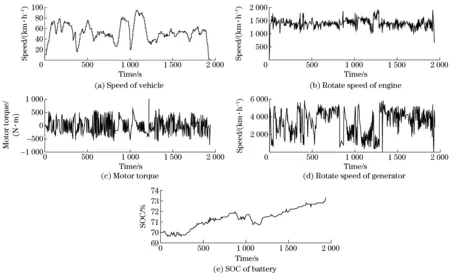
Fig.5 Vehicle driving conditions in cooling system simulation
3 Simulation results and analysis
Efficiency ofthe cooling system directly affects the vehicle efficiency. Simulation was done under the same conditions, power consumption of three cooling systems with different structures were changed with time, as shown in Fig.6.
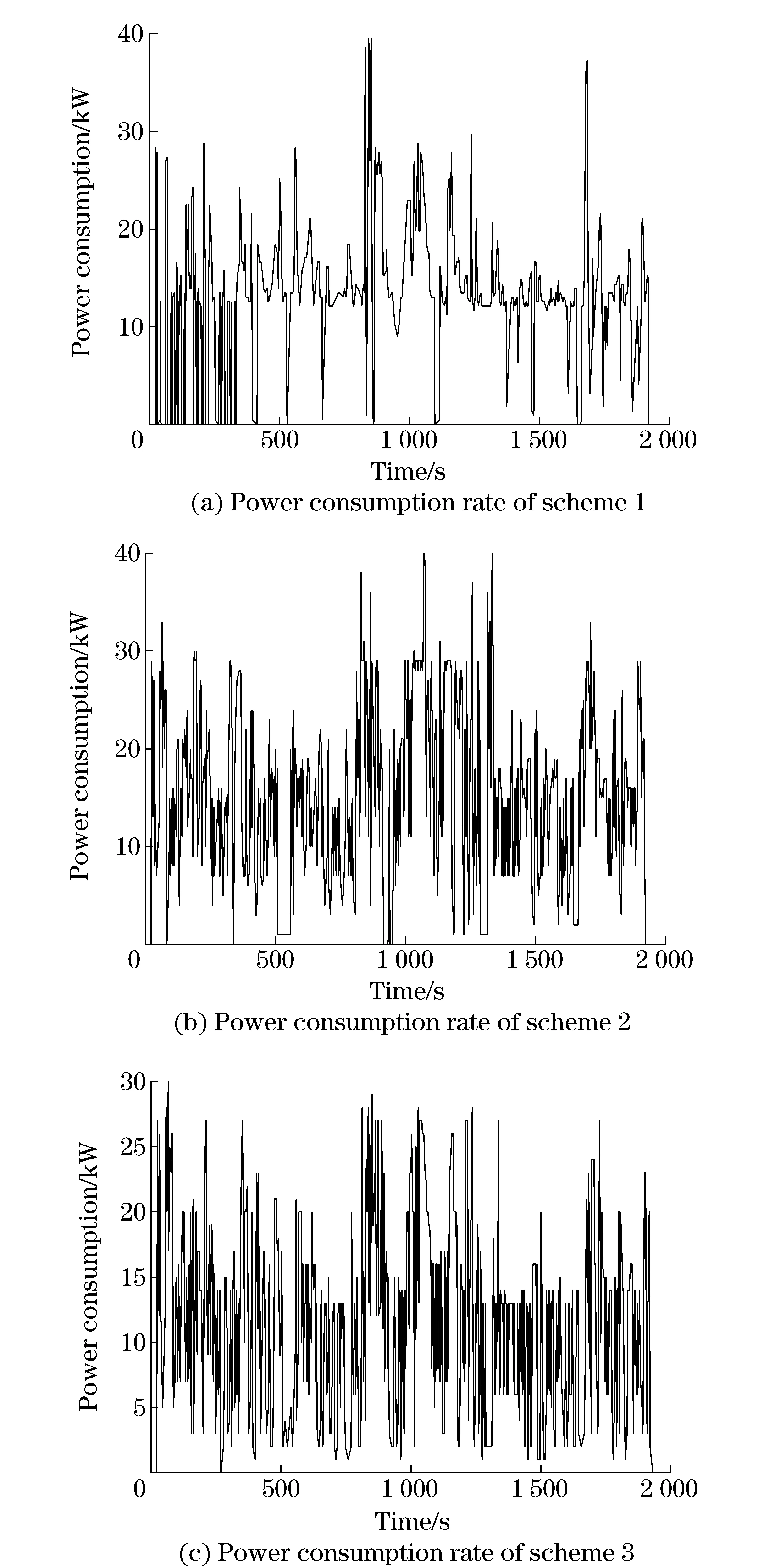
Fig.6 Power consumption rate of three different structures of the cooling system
From Fig.6, under the design nation working condition, the average power consumption of three cooling systems is between 15 kW to 20 kW, combined with the initial simulation conditions, the power consumption of cooling system accounts for about 10% of total output power of the power system. Integrated the instantaneous power of wasted about three cooling system on the time, the total power consumption can be obtained, as shown in Fig.7.
Compared the power consumption of cooling systems with three different radiator design schemes, the relationship of total power consumptions of the three schemes isP1 Fig.7 Simulation results of three different structures of the cooling system power consumption The cooling systems of power split HEV is complicated because it has many heat source components and the target temperatures of each heat source component are different. Using the numerical simulation method, a power system heat transfer model was built. Comparing the performance of three different schemes through the Simulink simulation, the best cooling system scheme was found. Base on characteristics of three kinds cooling system structures, the reasonableness of the simulation results are analyzed and verified. It can be seen from the result that the cooling system designation based on the numerical simulation can describe the cooling system performance accurately. This method can simplify the design process, improve design efficiency and provide a new way for designing a multi-heat source vehicle cooling system. [1] Cho H, Jung D, Filipi Z S, et al. Application of controllable electric coolant pump for fuel economy and cooling performance improvement [J]. Journal of Engineering for Gas Turbines Power,2007,129(1):239-244. [2] Traci R M, Acebal R. Integrated thermal management of a hybrid electric vehicle [J].IEEE Transactions on Magnetics,1999,35(1):479-483. [3] Park C W, Janra A K. Thermal analysis of cooling system hybrid electric vehicles, SAE paper 2002-01-0710[R]. Detroit: Society of Automotive Engineers,2002. [4] Park S, Jung D. Design of vehicle cooling system architecture for a heavy duty series hybrid electric vehicle using numerical system simulations[J]. Journal of Engineering for Gas Turbines and Power,2010,9(132):2802-2812. [5] Xiang Changle, Han Lijin, Liu Hui, et al. An analysis on the characteristics of power-split and coupling mechanism in series/parallel HEV[J]. Automotive Engineering,2010,3(32):183-187.(in Chinese) [6] Park S, Jung D. Numerical modeling and simulation of the vehicle cooling system for a heavy duty series hybrid electric vehicle, SAE paper 2008-01-2421[R].Rosemont:Society of Automotive Engineers, 2008. [7] Jung D, Assanis D N. Numerical modeling of cross flow compact heat exchanger with louvered fins using thermal resistance concept, SAE paper 2006-01-0726[R]. Detroit: Society of Automotive Engineers, 2006. [8] Incropera F P, Dewitt D P, Bergman T L, et al. Fundamentals of heat and mass transfer[M].6thEdition. Ge Xinshi, Ye Hong, trans. Beijing: Chemical Industry Press,2012:420-431.(in Chinese) [9] Sun Xiaoxia, Wang Yichun, Xiang Longyun, et al. A research on the braking control strategy with energy consuming braking for power split HEV[J]. Automotive Engineering, 2012,1(34):46-50.(in Chinese) (Edited by Cai Jianying) 10.15918/j.jbit1004-0579.201524.0106 TK 402 Document code: A Article ID: 1004- 0579(2015)01- 0035- 07 Received 2013-08 - 30 Supported by the Ministerial Level Advanced Research Foundation(40402070101) E-mail: wych@bit.edu.cn
4 Conclusion
猜你喜欢
杂志排行
Journal of Beijing Institute of Technology的其它文章
- Numerical simulation of the delay arming process of initiating explosive brakes
- Optimized design of biconical liner by orthogonal method
- Wideband acoustic source localization using multiple spherical arrays: anangular-spectrum smoothing approach
- Influence of eddy current on transient characteristics of common rail injector solenoid valve
- Novel miniature pneumatic pressure regulator for hopping robots
- Genetic-algorithm-based balanced distribution of functional characteristics for machines
